Roof challenge
DESIGNING A BIW ROOF OF A CAR WITH HEAT DISTORTION AND SNOW LOAD PREDICTIONS
OBJECTIVE
The objective of this project is to design a BIW Roof of a car with Front Roof Rail, Bow Roof Rail, Center Roof Rail, and Rear Roof Rail by following the engineering standards. The roof must be subjected to Draft Analysis for verifying whether it satisfies the manufacturing requirements. Curvature Study and Section Modulus Study needs to be carried out for the designed roof.
INTRODUCTION
The automotive roof plays an important role in the aerodynamics and the internal strength of the vehicle. The roof's BIW influences the aftermath effects of crush load, snow load, and heat distortion criteria. The roof has internal structures like front roof rail, rear roof rail, bow roof 1, bow roof 2, bow roof 3, and reinforcement center. In this project, these structures were designed accordingly. Their position was also justified with the required criteria.
Generally, roofs are given a curvature along with Xc and Yc. But some places of the roof have flatness compared to other sections, mostly while approaching the trailing edge of the roof becomes flat relatively. Sometimes this flatness is intentionally given to reduce the creation of a wake region while moving faster. The roof is like building a house. The house needs pillars, similarly, the roof needs the above-quoted internal structure to ensure safety and performance. The roof has to perform well in the roll-over test. The outer panel of the roof is considered a class A surface, so there cannot be any spot welds or any visible fastening. Mastics plays a major role in engaging the roof panel and the internal BIW parts.
SOFTWARE USED: SIEMENS NX12
AUTOMOTIVE ROOF
They act as a passenger cabin and protects from sun, rain, wind, dust, etc.
Roof variations
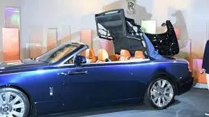
- Convertible roof
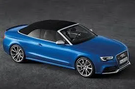
- Hardtop
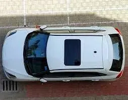
- Sunroofs
- T- tops
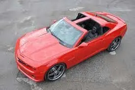
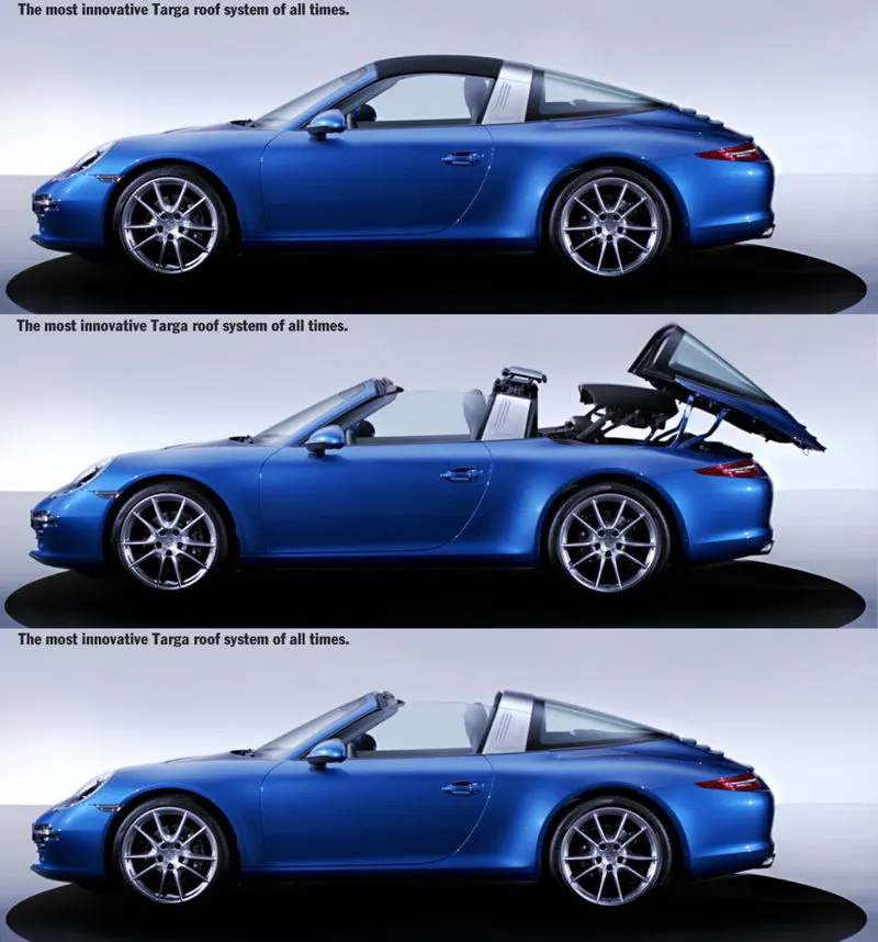
- Targa tops
- Vinyl roof
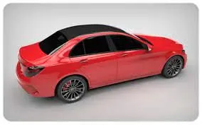
Apart from the aerodynamic shape of the roof, it has to withstand the induced drag force on surfaces. To make the roof more structurally rigid and to improve its local strength the BIW parts were designed. The internal components of the roof are
- Front roof rail
- Rear roof rail
- Reinforcement roof rail
- Bow roofs
These structures also facilitate cabin amenities like lighting and some other electrical electronic instruments.
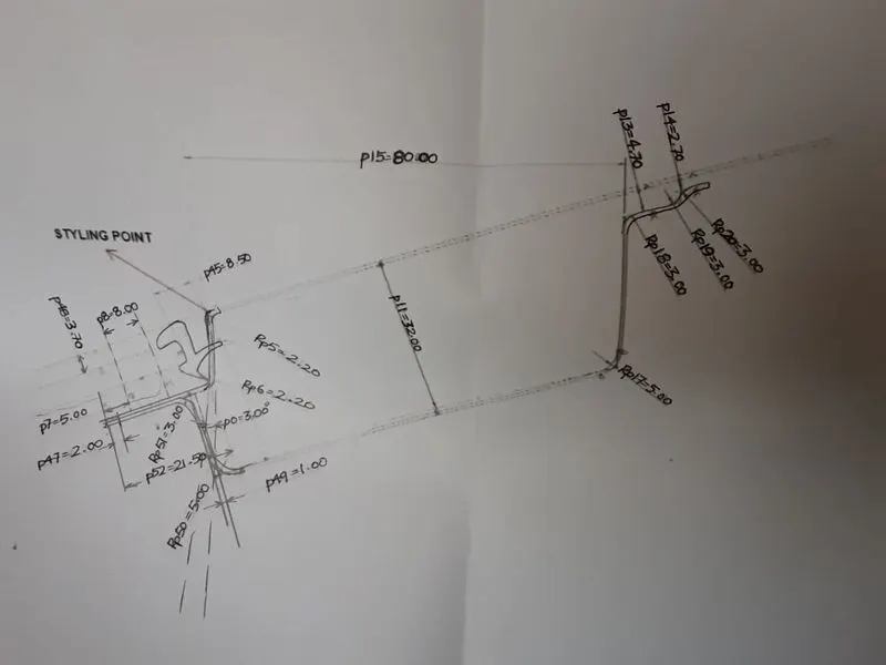
Master sketch of the front roof rail
The master sketch has all the geometrical details for the front roof. A space of about 21 mm is provided for the windshield, rubber lining, and mastic. The drawing angle is kept open for about 3degrees. The sealant requires at least of minimum 5mm gap. Whenever the inclination was provided for flanges the visibility criteria and the draw ability have to be considered. The offset surface distance of 32mm depends on the visibility of the driver and enough headroom clearance. The 80mm length depends on a surface match with the outer panel and also provides enough cabin clearance. On the right side of the roof rail, a clearance of about 3mm is given for mastic. Corner relief is given to deviate the stress concentration point.
FRONT ROOF RAIL
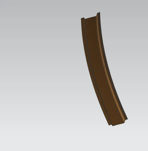
This part joins the windshield glass and the bodyside outer. The front roof is designed as per the available master sketch.
REAR ROOF RAIL
This part joins the back door and the bodyside outer. The rear roof provides enough space for back door hinge placement. The field of vision and headroom clearance are to be considered while dimensioning.
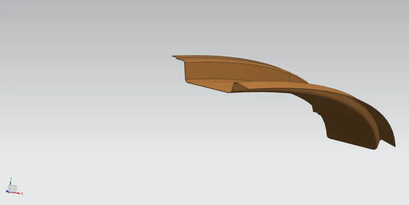
BOW ROOFS
The cottages were built with bow roofs to facilitate enough flexural stability while in case of strong winds. A similar situation is happening in the automotive roof. To control the strong induced current of winds the bow roofs were introduced. These bow roof's shape decides their resistance towards the bending load.
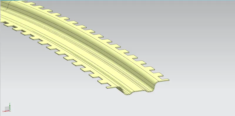
Bow Roof 1
The other two bow roof will look the same as in the above picture
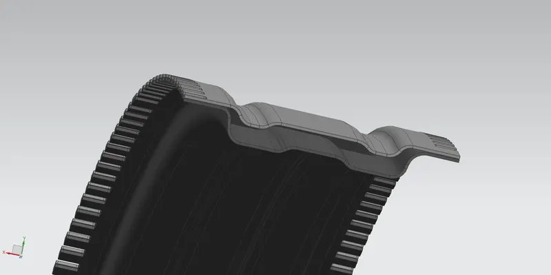
Reinforcement center
ROOF MASTIC POINTS
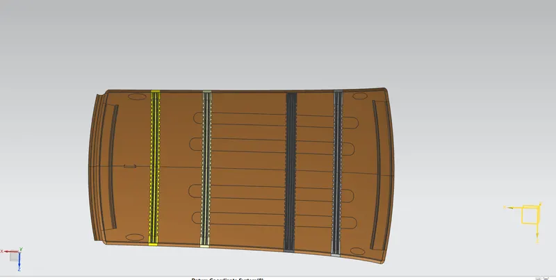
The roof rails were joined with the outer panel using mastic sealants this makes the part to be increased in strength locally.
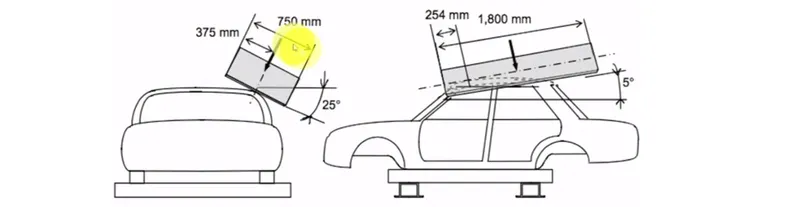
ROOF CRASH TEST
In this test, the vehicle roll-over strength is evaluated by giving induced force to the roof of automotive. The roof has to be much elastic to recover from deformation, which gives a good rating. The distance of protrusion inside the vehicle due to crush load increases the fatality rate of passengers.
DRAFT ANALYSIS OF ROOF RAILS
Draft analysis is done to check whether the part has any negative drafts which are miserable for manufacturing. The limiting angle of the negative is 5 degrees.
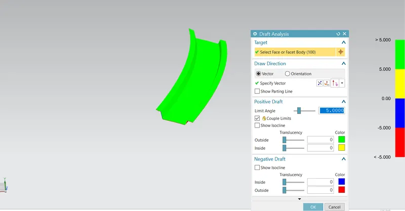
Draft analysis of front roof rail
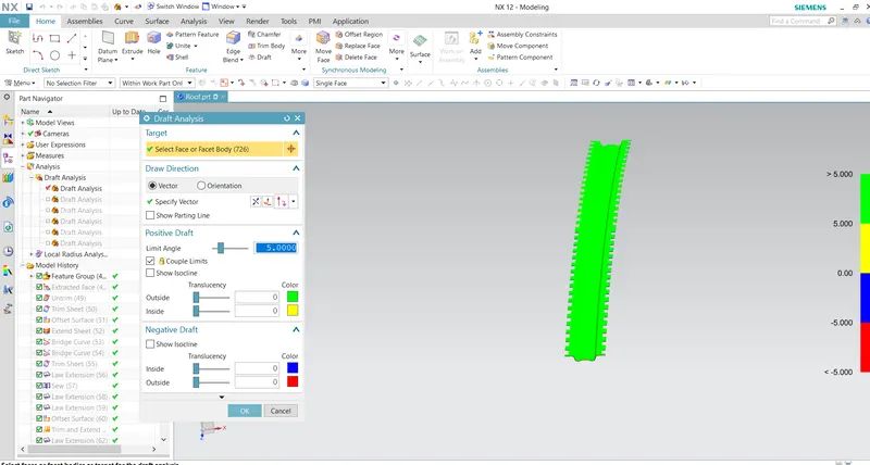
Draft analysis of the back roof rail
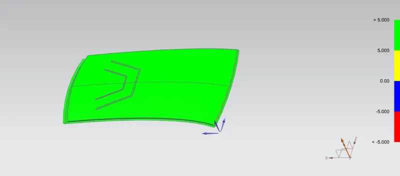
Draft analysis of roof surface
POSITIONING THE BOW ROOF RAILS
Bow roofs and the reinforcement rail has to be placed at appropriate locations to counteract and bear the imparted load. Their position is justified by heat distortion criteria, snow load criteria, and crash test analysis. Before entering into the analysis stage we can justify the position by heat distortion criteria and snow load criteria.
REASON FOR ROOF RAIL ORDER
I have positioned the bow roof and then followed by reinforcement center and then followed by two other bow roof's. The logic of a bow roof is to strengthen the flat surface. By considering it the roof outer panel has more flatness while approaching the trailing edge relatively with the leading edge.
HEAT DISTORTION
The material softens under increased temperature conditions. While applying load at this state makes the material much vulnerable to static loads.
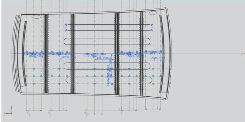
Curvature study
So to formulate this scenario the heat distortion criteria are introduced. The formula for heat distortion criteria is
W = [1.73 x 10^(-3) x L] + [1.85 x 10^(-8) x (R^2)/t] + [ 1.10x10^(-3) x l] - 2.68
Judgement Condition : OK< 2.7> 3.1
Where
L = Roof Length in X-Direction[mm](Roof dimension in 0-Y)
R = Roof curvature
R = 2(Rx*Ry)/(Rx+Ry)
Rx = X curvature
Ry = Y curvature
t = Roof plate thickness [mm]
l = Bow Roof Span [mm]
case1=Front roof rail to Bow roof 3
case2=Bow roof 3 to Reinforcement center
case3=Reinforcement center to Bow roof 2
case4=Bow roof 2 to Bow roof 1
case5=Bow roof 1 to Front roof rail
SLno Rx Ry L l t W OK/NG
case1 2568 7129 2128 262 0.75 1.64 ok
case2 3652 14535 2128 293 0.75 2.16 ok
case3 3348 21865 2128 515 0.75 2.4 ok
case4 5398 3340 2128 259 0.75 1.7 ok
case5 3992 1847 2128 253 0.75 1.43 ok
SNOW LOAD CRITERIA
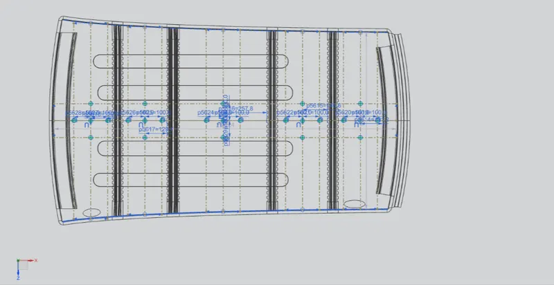
Curvature study
Qr = [Iy x t2] / [α x s x [(Rx + Ry)/2]2 x 10-8]
Where
α = My x Lx2 x 10-12 , My = Y(Ly-Y)
Judgement condition = Qr ≥ 3.1
250 ≤ s ≤ 380
t = Roof plate thickness [mm]
Ly = Distance between the front and rear roof Rails on the Vehicle along with 0Y[mm]
Length of Roof panel with the center point between Roof rail Front /Rear as the front and rear reference point.
Lx = Distance between the Left and Right end of the roof on the Roof BOW [mm]
Width of the roof panel exposed on the surface.
Y = Distance front Front Roof Rail to Roof BOW[mm]
s = Distance for which Roof BOW bears divided load [mm]
s = L1/2 + L2/2
Iy = Geometrical moment of inertia of Roof BOW (Y cross-section )[mm4]
Rx = Lateral direction curvature radius of roof panel Y cross-section on Roof BOW [mm]
Ry = Longitudinal direction curvature radius of roof panel X cross-section on Roof BOW [mm]
MOMENT OF INERTIA OF SECTIONS
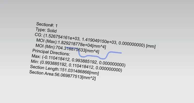
MOI OF BOW ROOF 1
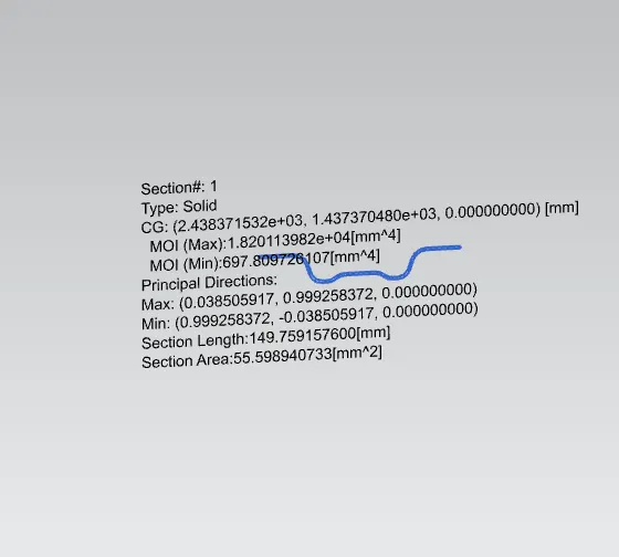
MOI OF BOW ROOF 2
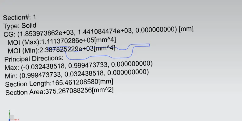
MOI OF REINFORCEMENT CENTER
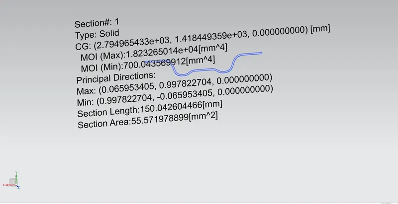
MOI OF BOW ROOF 3
case 1=Rear roof rail to Bow roof 1
case 2=Bow roof 1 to Bow roof 2
case 3=Bow roof 2 to Reinforcement center
case 4=Reinforcement center to Bow roof 3
SLno Iy α Lx Ly L1 L2 Rx Ry t Qr OK/NG
case 1 70431 0.72 1155 2018 321 328 4833 2212 0.75 13.51 OK
case 2 69980 0.68 1108 2018 328 584 3843 4371 0.75 7.49 OK
case 3 23878 0.96 1073 2018 584 357 3984 8363 0.75 0.77 NOT OK
case 4 70004 0.65 1053 2018 357 330 4333 13299 0.75 2.268 NOT OK
1.From the above results, the last two cases were failed to satisfy the judge mental condition.
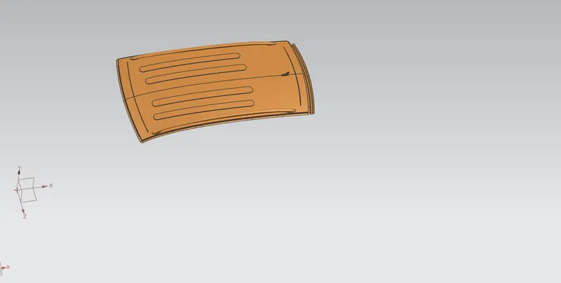
2.Hence to increase the strength and stiffness over the roof from center roof rail to rear roof rail where the Qr results were very low embosses
were provided.
3. The embosses over there will increase the roofs strength and stiffness drastically.
ROOF
CONCLUSION
The automotive roof is designed and the curvature study is done on the outer panel of the roof.