Week 8 - Challenge 1 - Draft Analysis on a Fan Cover
Tooling Axis Creation and Draft Analysis on a Fan Cover
Aim: To create the tooling axis for the given Fan cover model meeting the requirements of the draft angle and perform the Draft analysis on the model.
Why Draft angle is important:
Draft angle is the most important feature. A functional part for injection molding has to have drafts facing both cavity and core sides to reduce the risk of damage to the parts and ensure ejection. As the molten plastic flows into the closed die and fills the cavity, the material shrinks inside the mold upon cooling and as a result grips the core. Draft angles should be at least 30 to facilitate the part ejection.
- Reduces the chance of damage to the part due to friction during release.
- Reduces wear and tear and chances of damage to the mold.
- Ensures a uniform, smooth, unscratched finish when required.
- Ensures the integrity and uniformity of other surface finishes and textures.
- Reduces overall cooling time by lessening or eliminating the need for unconventional ejection setups.
Cavities: Cavities are areas of the mold where the part is formed into the desired shape. Molds must be balanced, so there are typically only a certain number of cavitations allowed.
Core: A protrusion or set of matching protrusions, which form the inner surface of a plastic part. They are often considered the "male" side of the part.
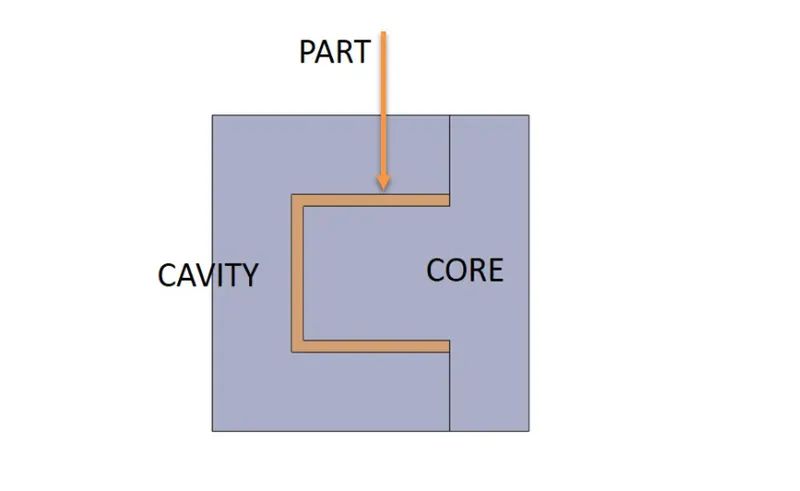
Tooling Axis:
• This is the axis or direction in which the core and cavity will open and all the features of the part are carried away.
• This axis helps in the manufacturing of parts.
Draft Analysis using CATIA V5
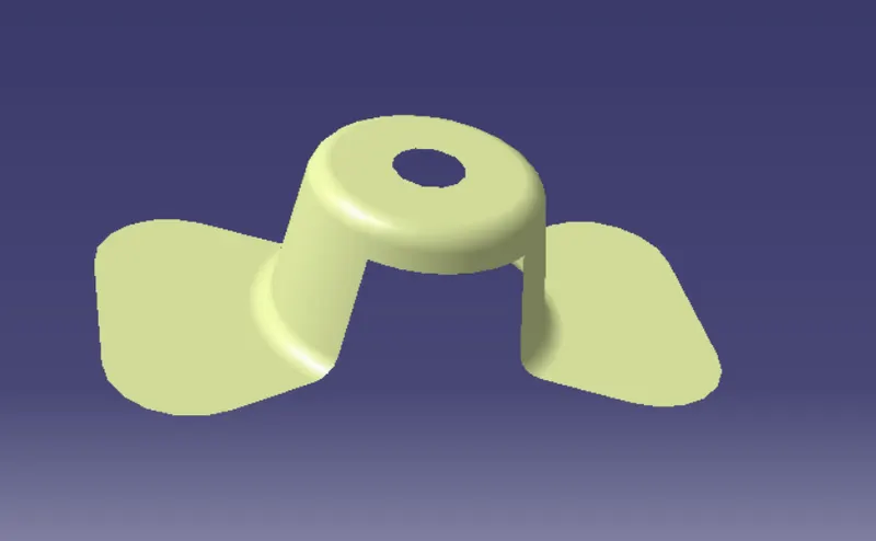
Given data, Class A surface.
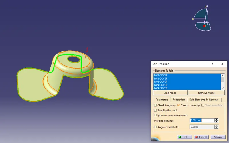
First, we need to check the connectivity of a given part, this can be done using the 'join surface' command or using the 'Boundary' command.
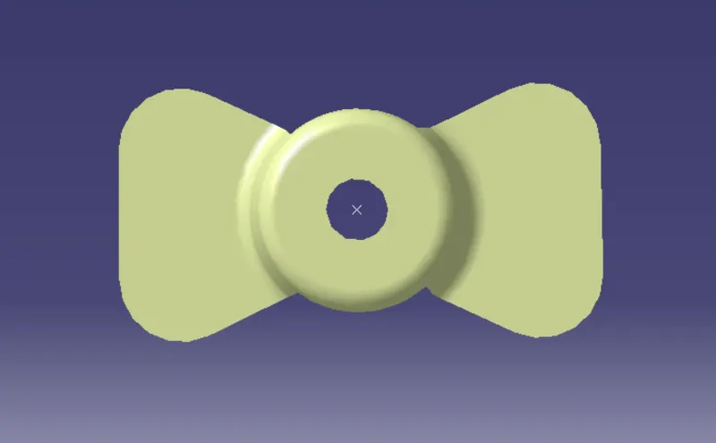
Now we have to decide in which tooling direction the part will clear.
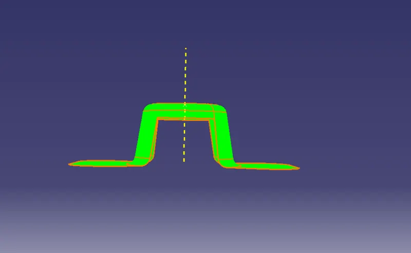
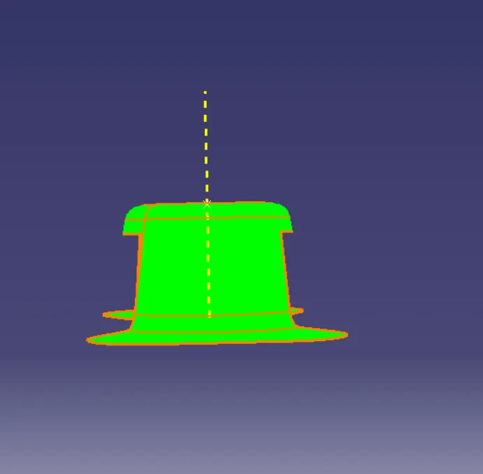
By visualizing the part, we can decide that tooling direction we be z-axis. so, we are creating a dummy tooling axis.

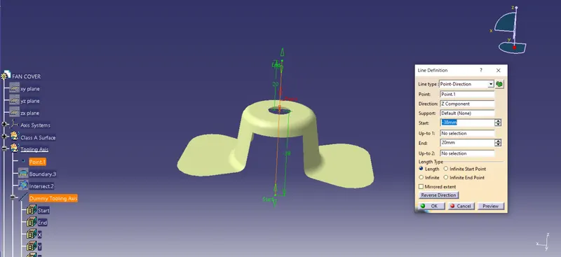
Considering Y-axis, creating intersection boundary with ZX Plane
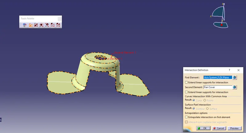
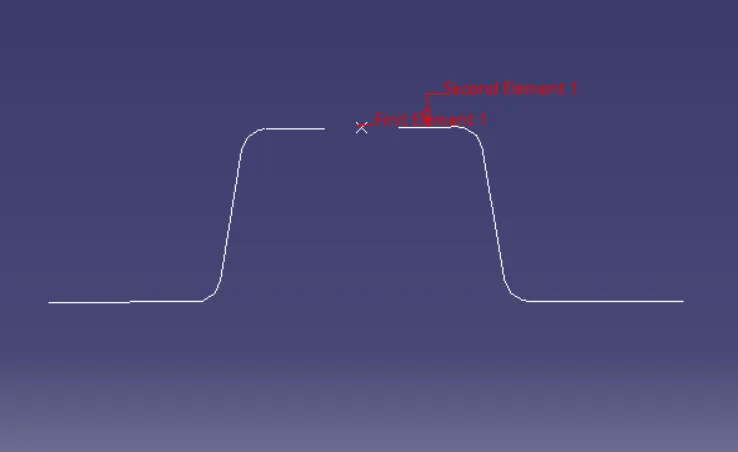
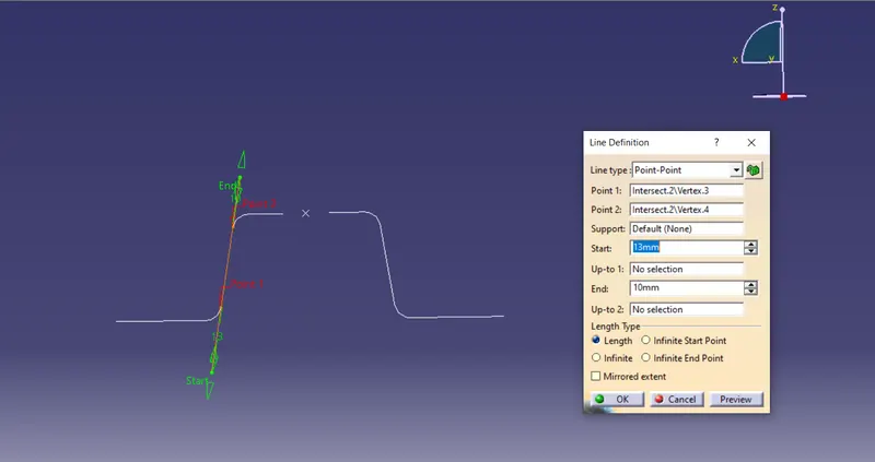
Then creating lines through the points of the face which we think can create issues with removing the core and cavity.
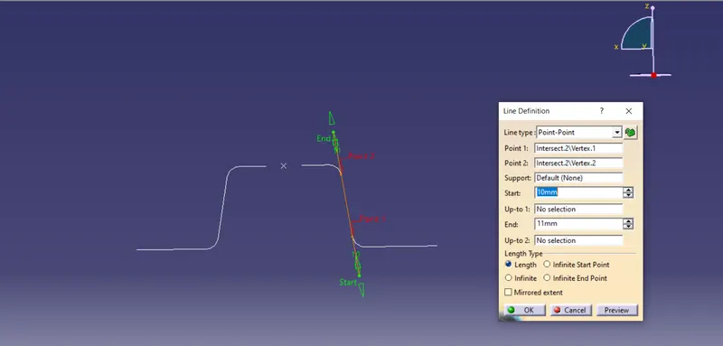
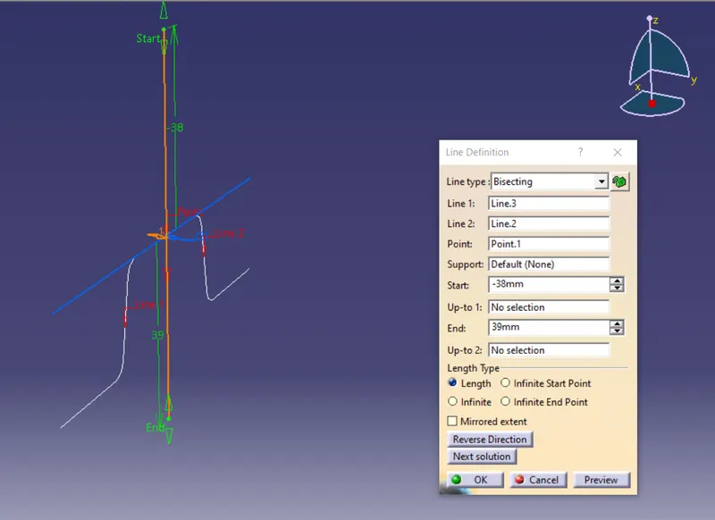
Creating bisecting line through the above lines and the center point. This will be named as Y-Direction Tooling Axis.
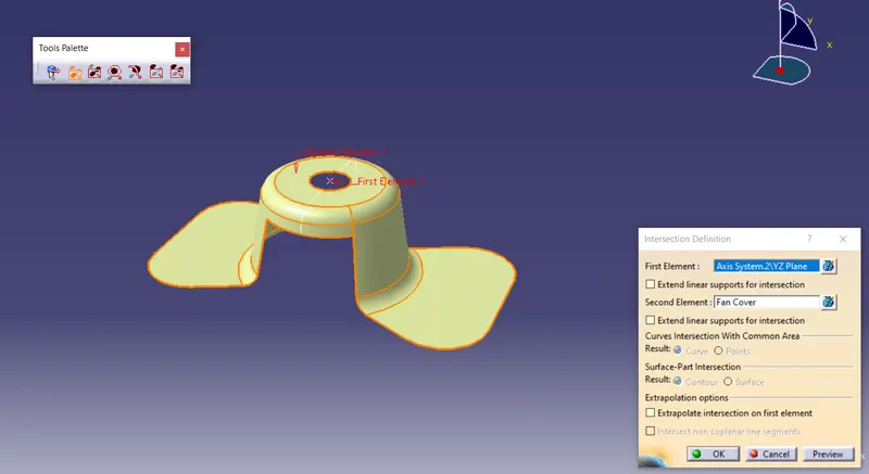
Considering X-Axis, creating intersection boundary with YZ plane.
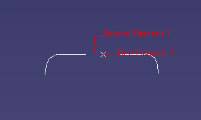
Then creating lines through the points of the face which we think can create issues with removing the core and cavity.
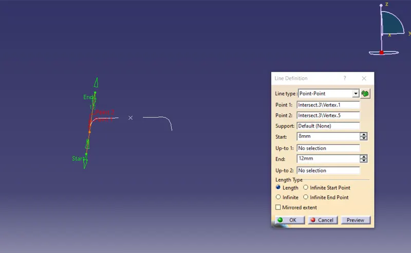
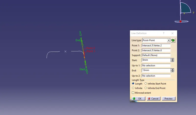
Creating bisecting line through the above line and the center point. This will be named as X-Direction Tooling Axis.
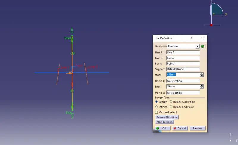
Now creating Bisecting line by selecting X-Direction Tooling Axis and Y-Direction Tooling Axis and naming it as Main Tooling Axis.
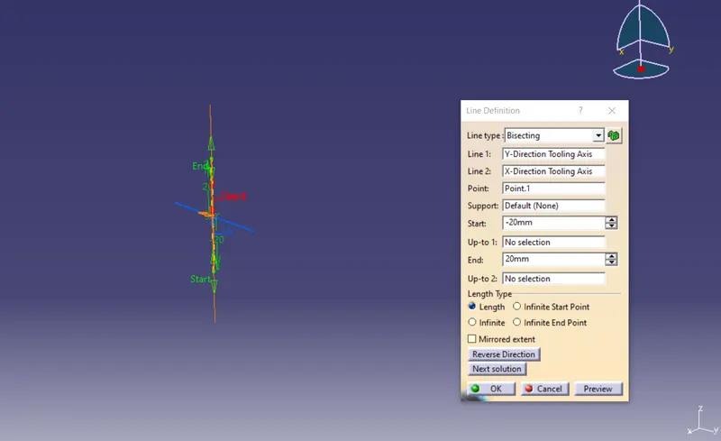
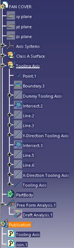
Publishing the Main Tooling Axis and class-A surface.
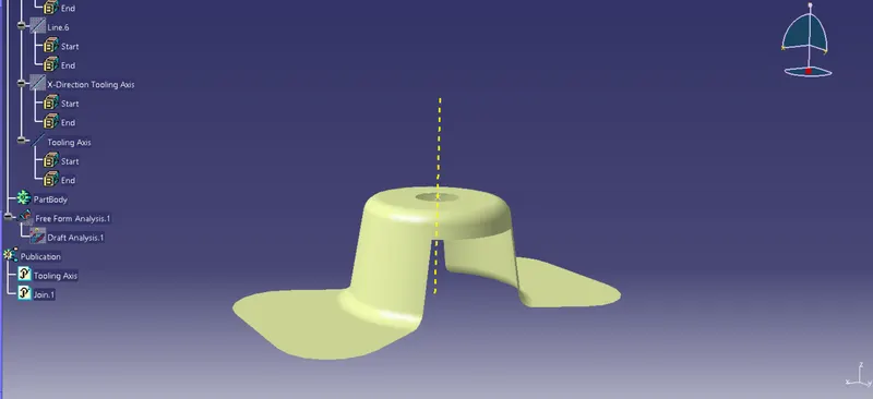
Draft analysis, Insert ->Analysis-> Feature Draft Analysis.
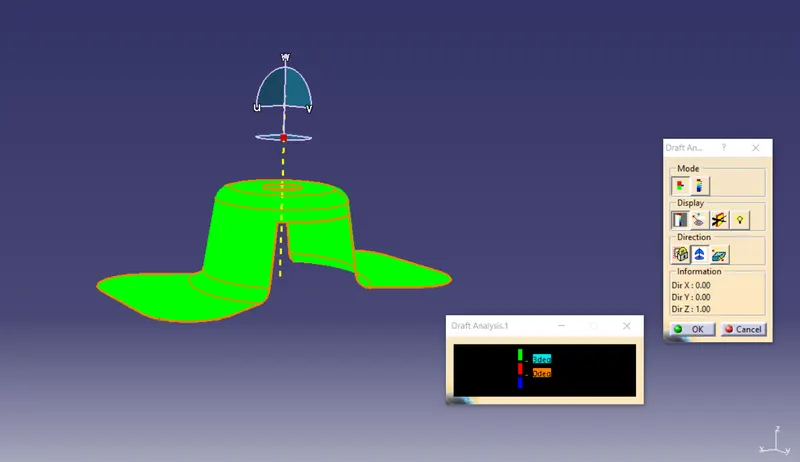
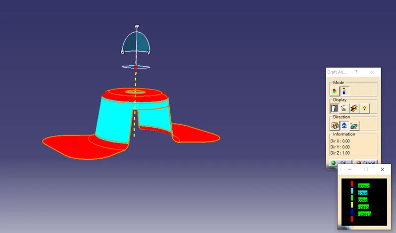
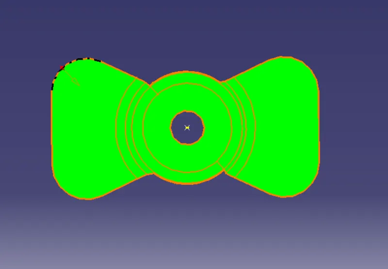
Tree Structure
Conclusion
Thus the draft analysis for fan cover is carried out by creating perfect tooling direction and the given Class-A surface was ready to move on to further operations.