Advanced Sheet Metal Design Using NX Cad Challenge_6_Bracket
Design of Sheet Metal Bracket Using Nx Cad
Objective:
The objective of this tool is to create a sheet metal Bracket using the Nx cad tool
Introduction:
Sheet metal is metal formed by an industrial process into thin, flat pieces. Sheet metal is one of the fundamental forms used in metalworking, and it can be cut and bent into a variety of shapes. Every day countless objects are fabricated from sheet metal. Thicknesses can vary significantly; extremely thin sheets are considered foil or leaf, and pieces thicker than 6 mm (0.25 in) are considered plate steel or structural steel
Sheet metal is available in flat pieces or coiled strips. The coils are formed by running a continuous sheet of metal through a roll slitter.
Design Methodology:
Description of tools/features:
- 2D sketch
It's a basic 2d sketch to any design.
- counter flange
Creates a base feature by extruding a sketch along a vector or adds material by sweeping a sketch along an edge or change of edge.
- Normal cut
Cuts material by projecting a sketch onto the model and then cutting perpendicular to the face intersecting by the projection.
- Break corner
Rounds or chamfers a sharp corner of a tab or flange.
- Unbend
Flattens a bend and the material adjacent to the bend
- Rebend
Restore an unbend feature to its previous bent stage, along with any feature added after the unbend feature.
- Bead
Lifts material along the contour of a sketch that simulates a stamping tool creates a solid using a path and cross-section shape.
- Hole
Creates a hole in the surface of the body.
Screenshots of the Model:
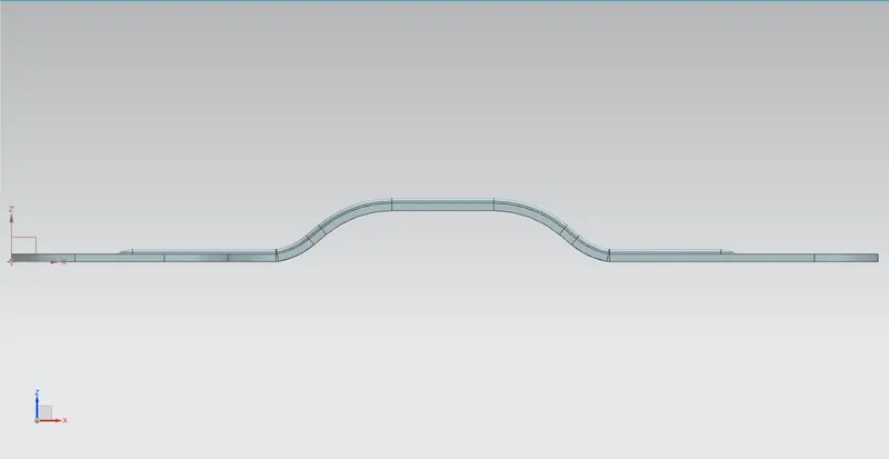
- Front View
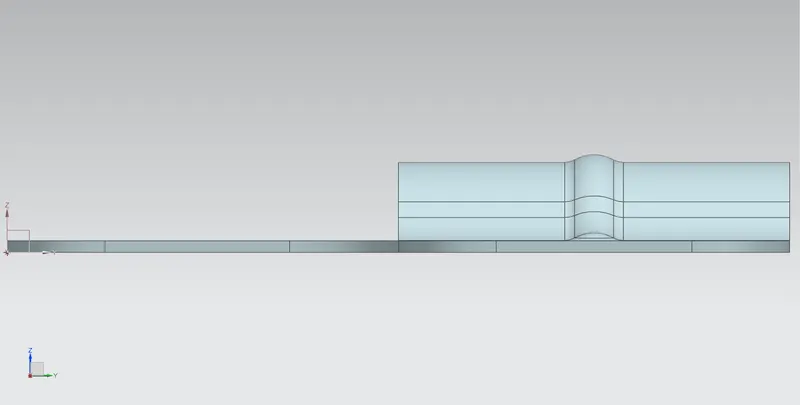
- Side View
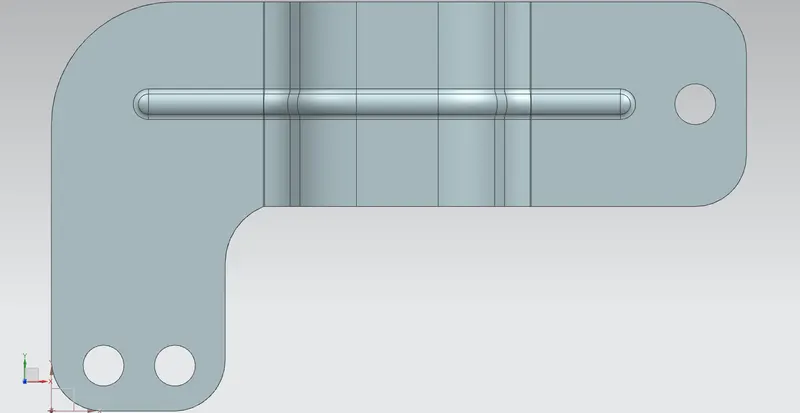
- Top View
- Isometric View
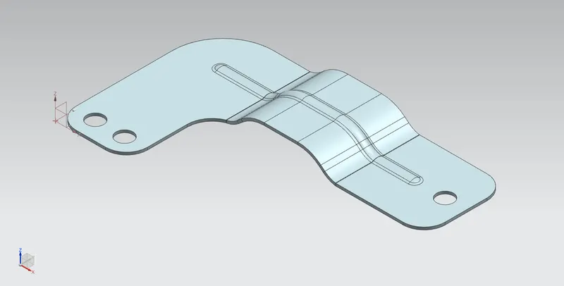
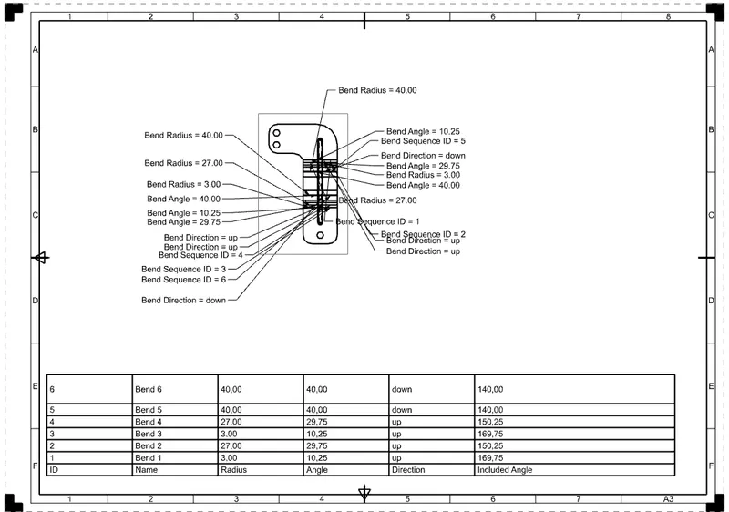
Drafting
Conclusion:
We have designed a sheet metal Bracket using Nx cad and by designing this I have learned some new commands in sheet metal