Fender Design Challenge
DESIGN OF FENDER
FENDER:
A fender is the part of an automobile, motorcycle, or other vehicle body that frames a wheel well (the fender underside). Its primary purpose is to prevent sand, mud, rocks, liquids, and other roads spray from being thrown into the air by the rotating tire. Fenders are typically rigid and can be damaged by contact with the road surface.
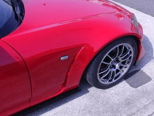
Sticky materials, such as mud, may adhere to the smooth outer tire surface, while smooth loose objects, such as stones, can become temporarily embedded in the tread grooves as the tire rolls over the ground. These materials can be ejected from the surface of the tire at high velocity as the tire imparts kinetic energy to the attached objects. For a vehicle moving forward, the top of the tire is rotating upward and forward and can throw objects into the air at other vehicles or pedestrians in front of the vehicle
TYPES OF FENDER:
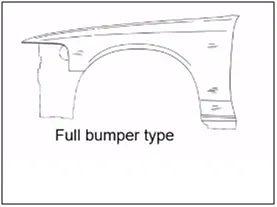
- Full Bumper type
The full bumper type fender was used in old cars, it covers the full area until the front lighting. But it has a lot of sheet metal material which is unnecessary and increases the weight of the fender. These types of fenders are no longer used in automobiles.
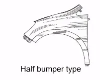
- Half Bumper type
Half bumper fender is used because the waste of material is less & can produce two fenders at the same time by slightly increase the raw sheet. and to reduce the weight & cost mostly half bumper type fenders are been produced.
STYLING DATA:
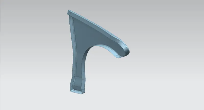
MOUNTINGS IN FENDER:
- Bumper
- Drip
- A-Pillar
- Sill
- Cowl
Design Software used:
NX 12 (CAD)
Design of Fender :
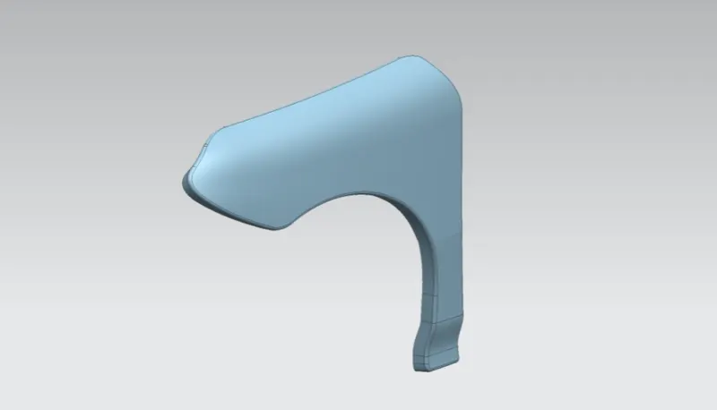
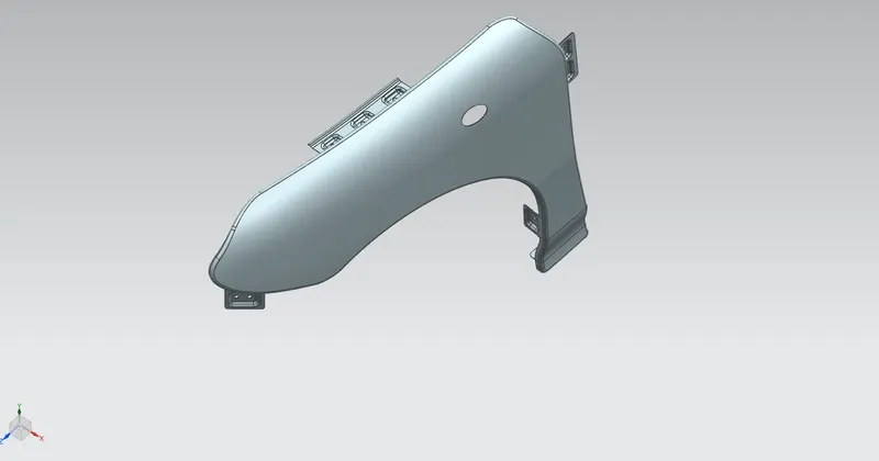
The main objective here is to design the Drip area, Bumper mounting region, Sill mount region, A-Pillar mount region and Splash cover or wheel well mount regions for the given fender skin or styling surface.
Design Considerations:
- Embosses are provided to increase strength.
- The corners of the flanges are smoothened to ease the producibility of the part.
- Fillet of 2-3mm is provided to avoid sharp corners and edges.
- Cutouts are provided at certain regions in order to save as much material as possible.
- Uniform wall thickness of 0.75 mm is maintained.
- Drip area:
Data are given for designing drip area
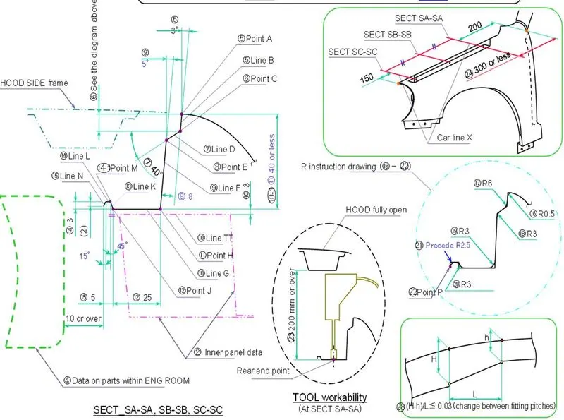
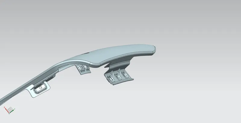
2.Pillar mount region:
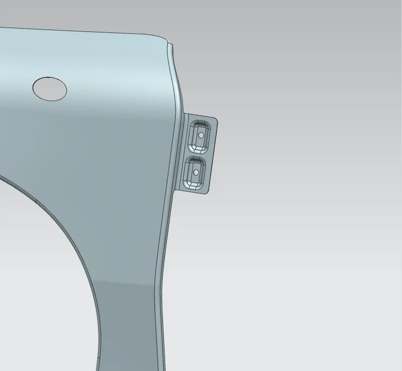
3.Bumper mount region:
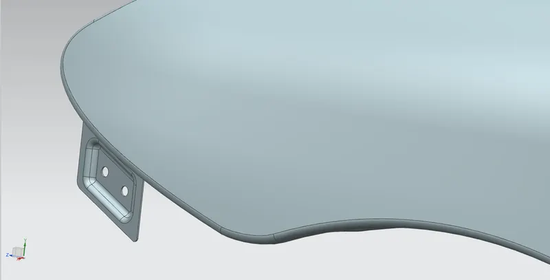
4.Sill Mount region:
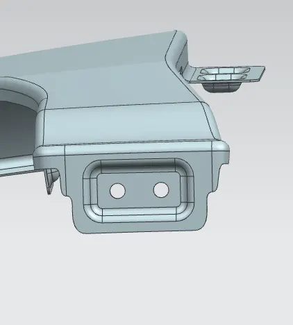
5.Wheel mount region:
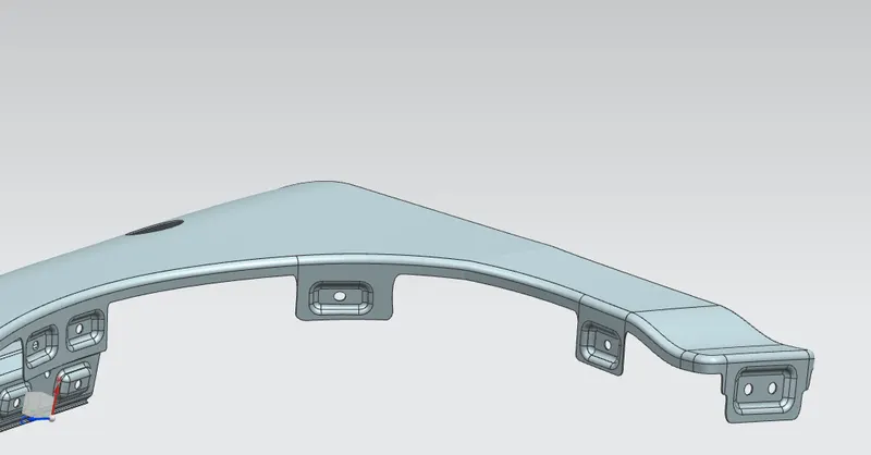
6.Slot For Mounting turn signal:

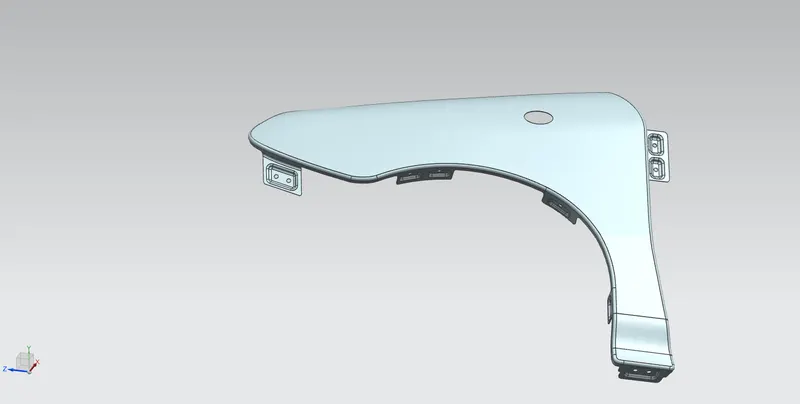
FINAL FENDER DESIGN:
CONCLUSION:
Hence we have designed all parts of the fender by using given styling data.