Reinforcement detailing of Columns from ETABS output
Question
The ETABS file for a G+4 building is provided. Run the analysis and design of the RCC Moment Resisting Frame. The following challenge deals specifically with two columns at the following grid intersections.
- 3A
- 3B
Provide details of longitudinal reinforcement for the two columns, from foundation to terrace level. Sketch the column cross-sectional & elevation details or draft it using AutoCAD software.
Show shear reinforcement & lapping details as per the special confining reinforcement provision of clause 8.1 of IS 13920 - 2016.
Answer
Aim: Reinforcement detailing of columns in Etabs 2018.
Introduction: The ETABS file for a G+4 building is provided. Run the analysis and design the RCC Moment Resisting Frame. The following challenge deals specifically with two columns at the following grid intersections.
- 3A
- 3B
Provide details of longitudinal reinforcement for the two columns, from foundation to terrace level. Sketch the column cross-sectional & elevation details or draft it using AutoCAD software.
Show shear reinforcement & lapping details as per the special confining reinforcement provision of clause 8.1 of IS 13920 - 2016.
Procedure:
Step 1) Open the Model for which You Want to Design Columns in ETABS
- Double click on the ETABS shortcut on your desktop or run it from the start menu.
- Wait for it to load till the ETABS opening screen appears on your computer.
- From the ETABS opening screen go to the open files option available on the left-hand side of the screen.
- Browse for the building model you saved on your local disk.
- Click on open and wait for the model to be run in the software.
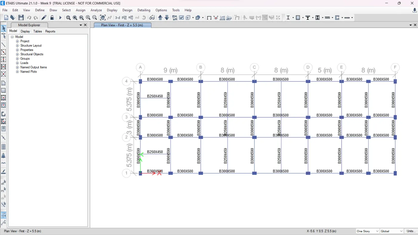
Step 2) Adjust the View Settings
- As we know that ETABS is a 3d analysis tool that produces excessive results regarding each and every structural member.
- Therefore, we need to separate the results for the frames we want to design by adjusting the view settings in ETABS.
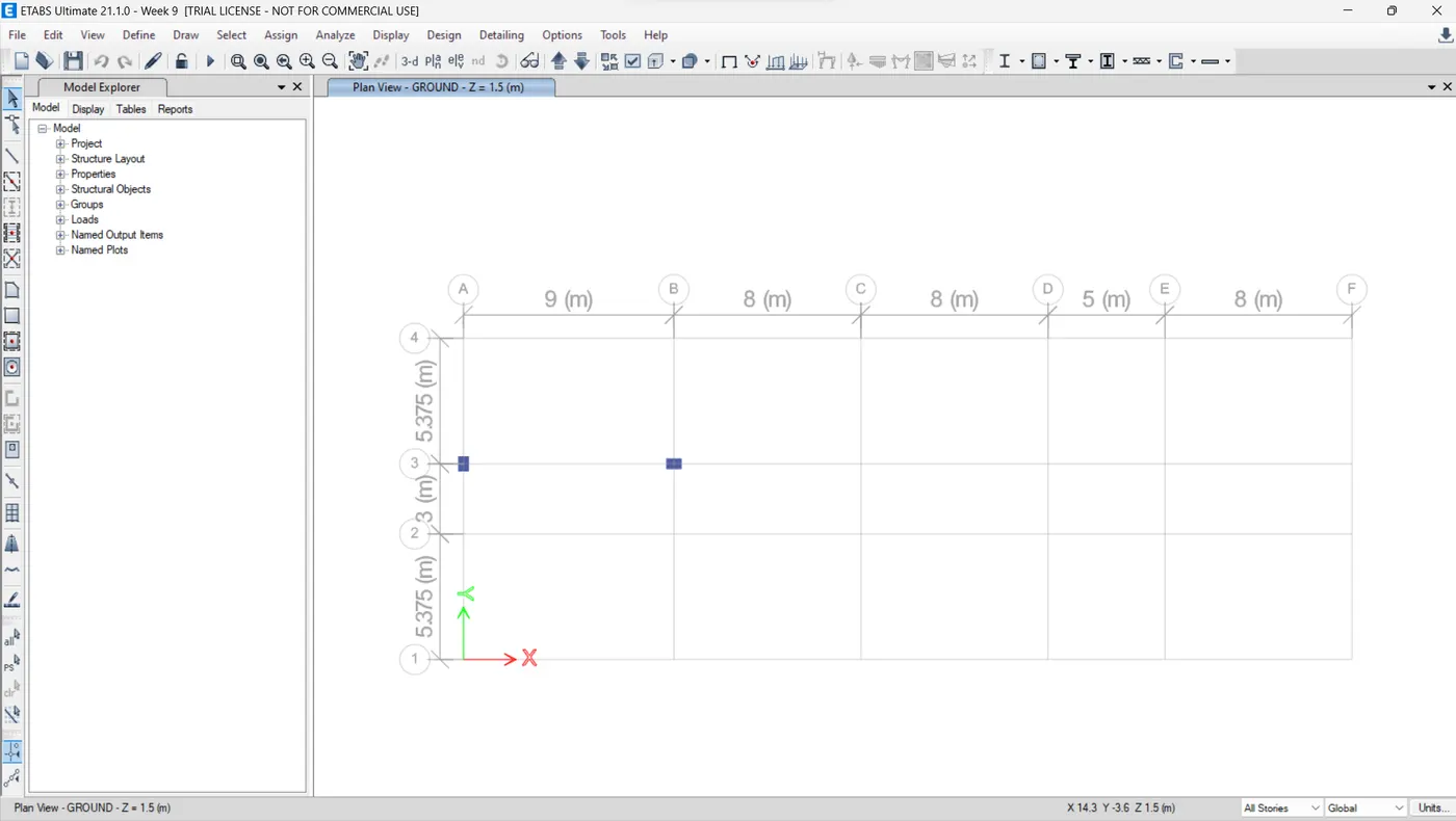
- And in our case, we need to focus on two columns at grid positions A3 and B3. So, we will separate these two columns as explained below.
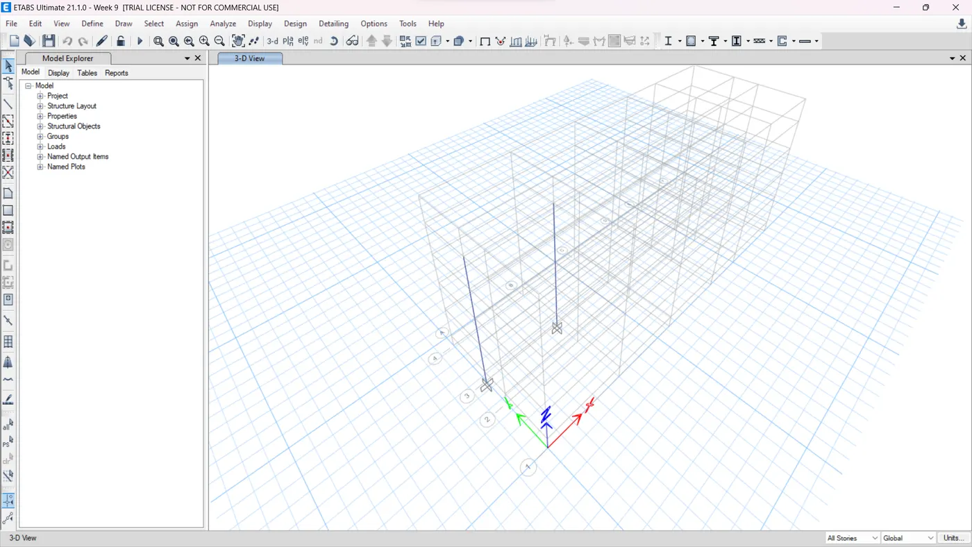
- So, select the two columns on grid positions A3 and B3 then right-click on your ETABS screen and select the option called view only selected.
- This way, all other objects except the selected columns will be automatically hidden by the software and it will be a lot easier to understand the results for the said columns.
Step 3) Run the Analysis and Consequently Run the Frame Design
- You can run the analysis by pressing F5 on your keyboard or you can also run it by clicking on the play button available on the toll ribbon of ETABS.
- After this, you can go ahead and set the design standards from the frame design dropdown option and then run the frame design.
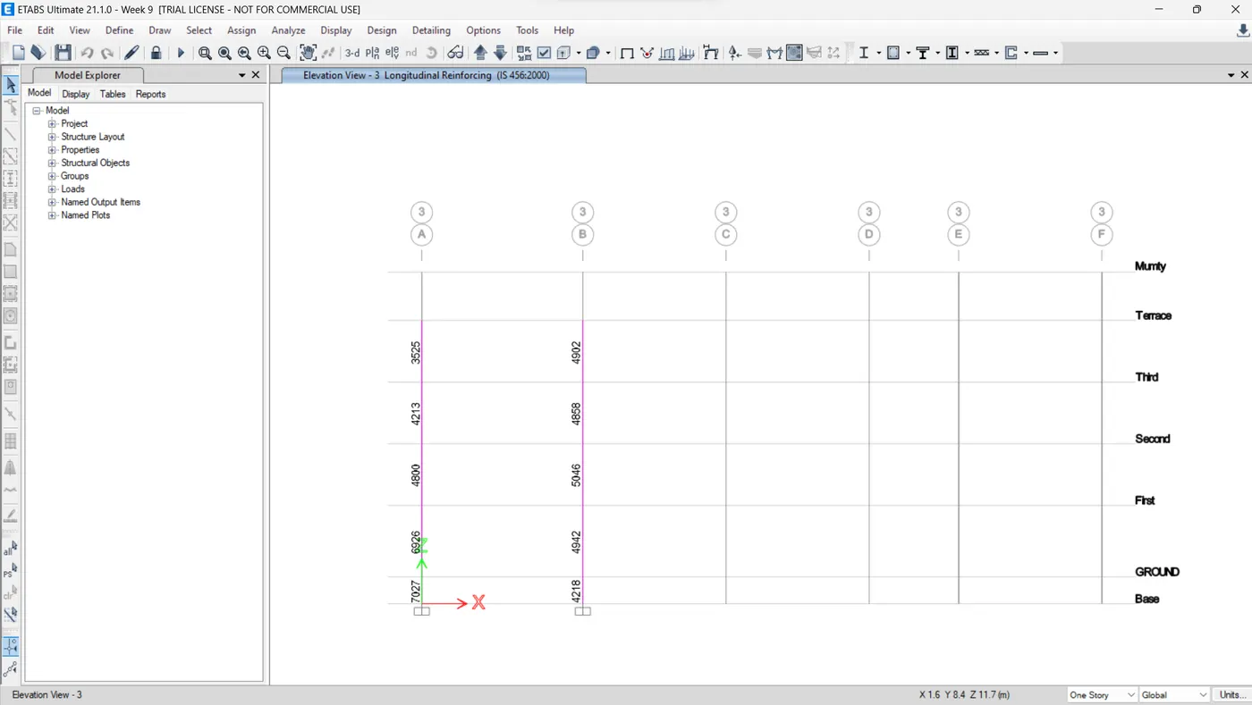
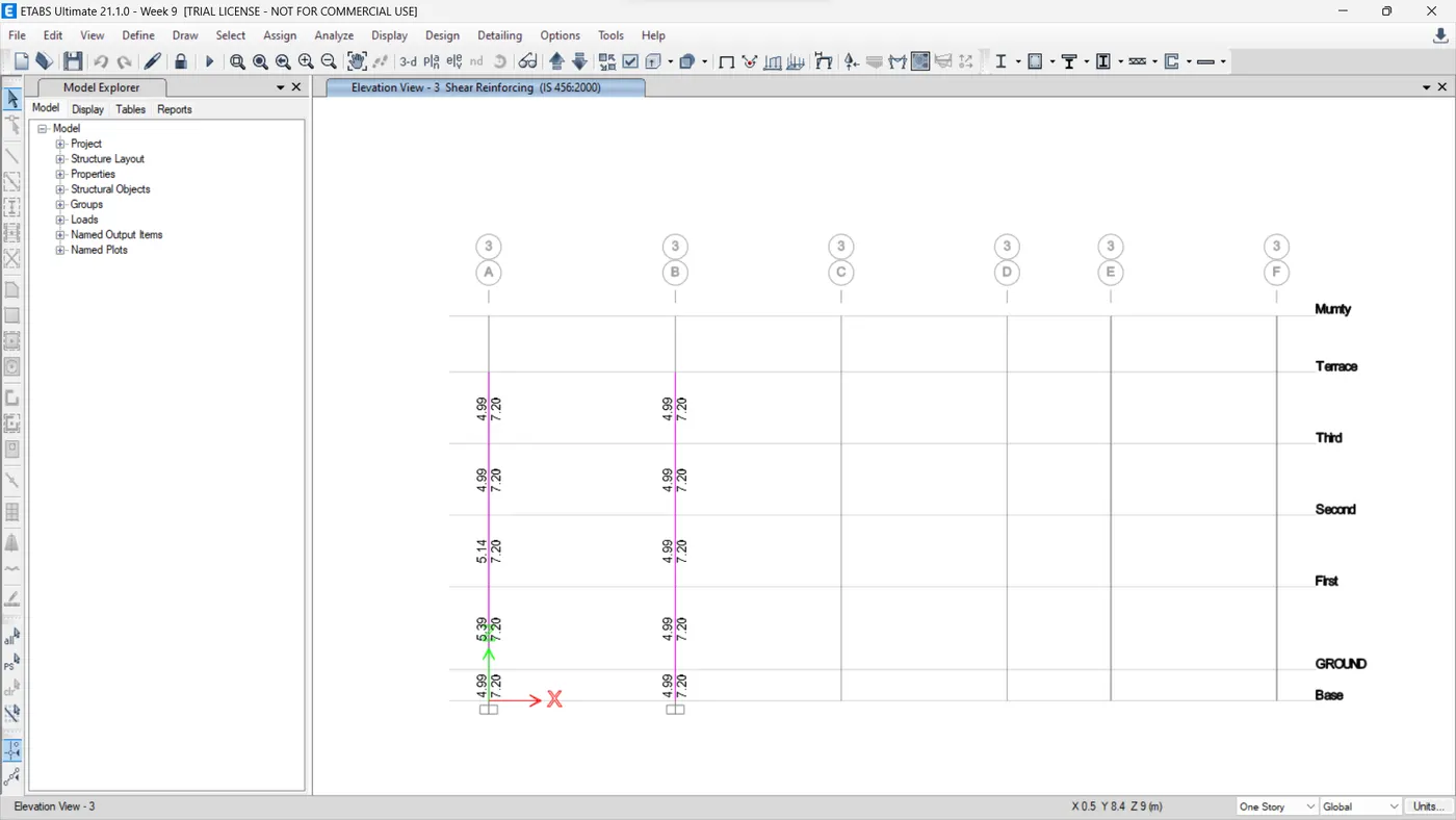
- Once you complete the frame design ETABS will initially show the amount of longitudinal reinforcement required for the columns.
- However, you can display the required results like the shear reinforcement requirement from the display design info option from the same frame design dropdown.
- So, in the same way, the following results for the longitudinal as well as shear reinforcement requirements were obtained from the software as inserted below.
Step 4) Execute the Reinforcement Detailing Using AutoCAD
- Now that we have the amounts for which we have to provide the reinforcement, we can go ahead and execute the detailing using the AutoCAD software.
- So, as we know AutoCAD is a 2d drawing tool that allows us to draft Architectural as well as Structural details of a building.
- And when it comes to drawing the reinforcement detailing of the structural members, AutoCAD is by far the most efficient tool available to our hands.
- However, we need to carry out certain calculations before drawing the details.
- Therefore, the calculations followed by the drawings for both of the columns are executed in the following sections.Provide 8mm Lateral Ties.Length of the confinement region(L0)
COLUMN 3A
Building Base to First Slab
1. Longitudinal Reinforcement
- As obtained from the ETABS output, the maximum Ast required is at the base of column and the value for the same is of 6926mm^2.
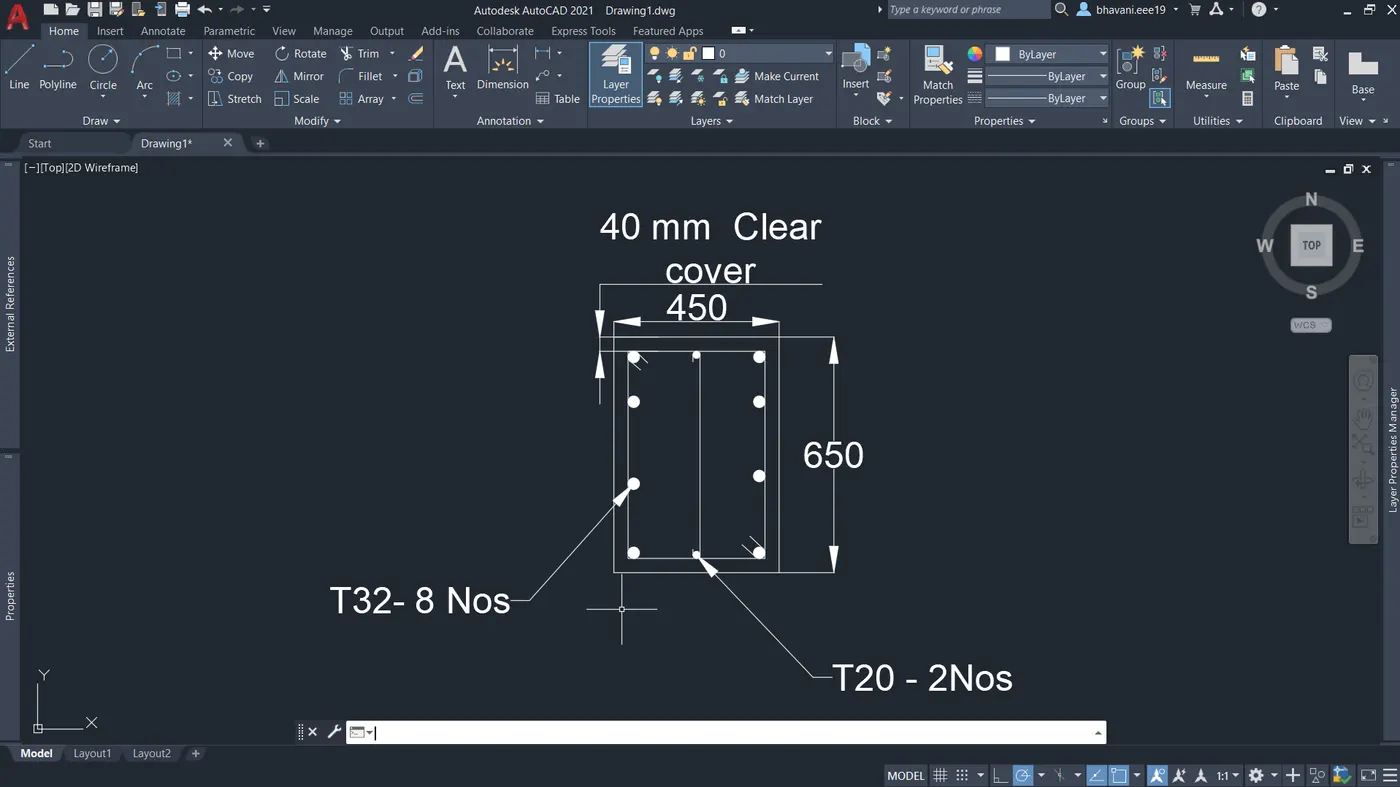
- Hence, if we provide 8 bars of 32mm dia and 2 bars of 20mm dia.
Ast = (8x804) + (2x314) = 7060 > 6926.Hence OK.
2. Shear Reinforcement
- Provide 8mm Lateral Ties.
3. Confinement Arrangement
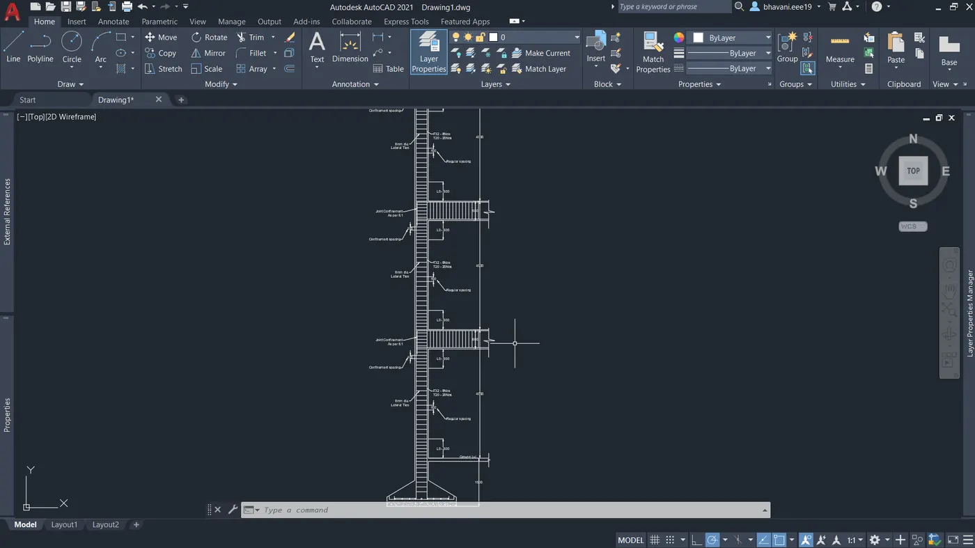
Length of the confinement region(L0)
- Larger lateral dimensions of the member where yielding occurs
- 1/6 th of the clear column span
- 450 mm,whichever is greater
So in our case,we have the total beam depth of 600mm.Therefore,we sall consider the confinement region upto the 600mm from beam bottom towards the mid span on either side of the column.
Shear spacing within the confinement region
- 1/4 th of the smaller lateral dimension of column
- 6 × db
- 100mm,whichever is lesser
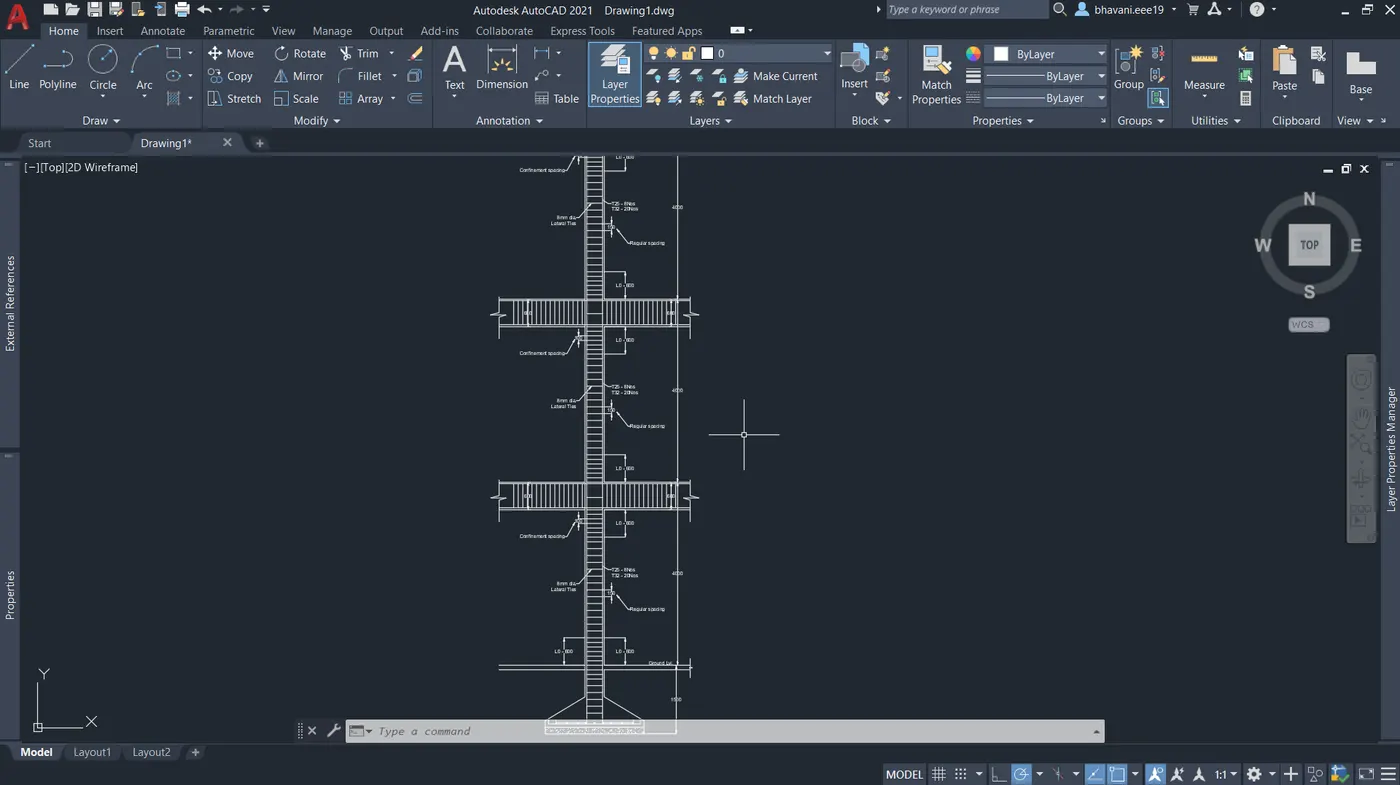
So,100mm is the least value we got among all three above values.Therefore, provide 100mm c/c spacing within the confinement zone and go with 150mm c/c for the mid zone of the column.Thus,using the above values the following detailed drawing was prepared in AutoCAD for the column height from the building base upto the top floor of the building.
COLUMN 3B
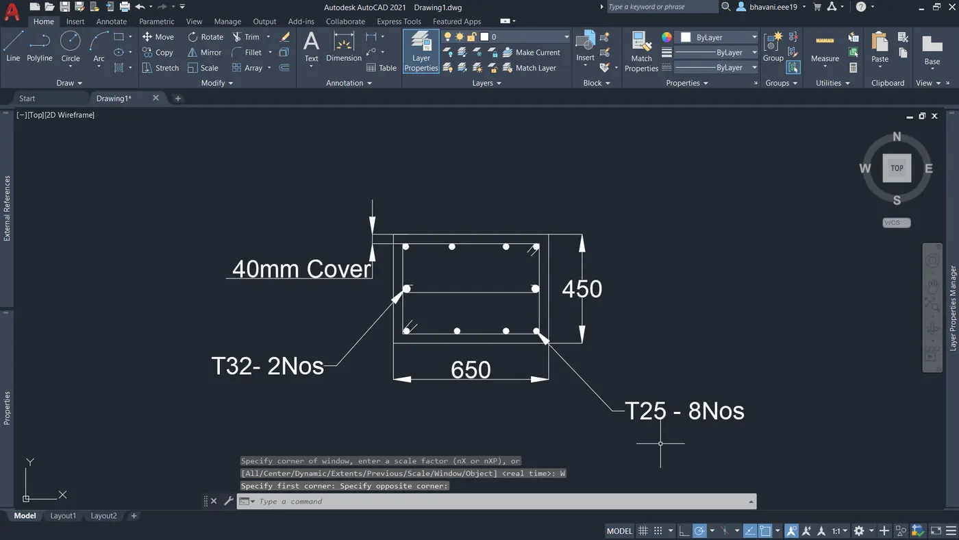
Result:
Thus the detailing of two RC columns were done using AutoCAD and special confininf reinforcement is verified with respect to IS13920 clause 8.1.