Project - Speed Control of a Direct Current (DC) motor
Project Report / Solution :
Objective :
In this project, a Simulink model for the DC motor will be first developed per the schematic shown in Figure. Use the Proportional, Integral, and Derivative (PID) control design knowledge gained in the training to design, develop and test a controller to maintain a desired speed for the motor.
Motor Design & its parameters :
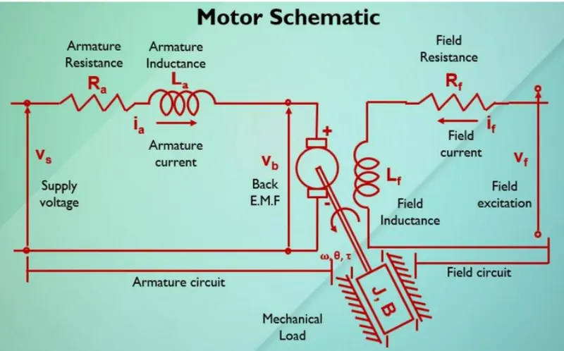
We have to apply kirchoffs law in armature circuit part only ,
`L * di/dt +RI = V -Kb* d theta/dt` -----------(a)
Now apply newtons law on motor load & its shaft portion ,
`J d^2theta/dt ^2 + B d theta/dt = Kt * I` -----------(b)
Converting above equations to s domain and solving for I & `omega`
`I(s) = (V(s)- Kb*s theta (s))/ ( Ls+R)` -----------(c)
`omega(s)=s theta (s)= (Kt*I(s))/(Js+B)` -----------(d)
Put the equation c in below equation
`J s^2 theta (s)+ B s theta (s)= Kt*I(s)`
`J s^2 theta (s)+ B s theta (s)= Kt * (V(s)- Kb*s theta (s))/ ( Ls+R)`
`s theta (s) [(Js+B)(Ls + R)+(Kt*Kb)] =Kt*V(s)`
Transfer function of output angle theta to input voltage V(s) given by
`Ga(s)= (theta(s))/(V(s) )= ((Kt))/ (s (Js+B)(Ls + R)+(Kt*Kb))` -----------(h)
Transfer function of output angular velocity (omega) to input voltage V(s) given by
`Ga(s)= (omega(s))/(V(s) )= ((Kt))/ ( (Js+B)(Ls + R)+(Kt*Kb))` `-----------(i)
With the help of above equations we can design the DC motor in laplace domain as mentioned below by using equation (c) & (d), Also we can refer it as motor deisgn without converter.
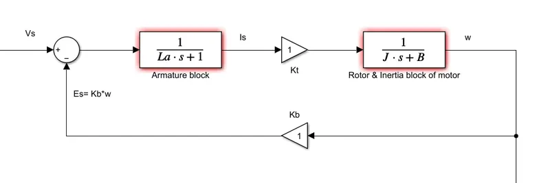
Fig 1 : Design of DC motor in Laplace domain
State space representation for above design in the form of matrices is given below ,
`Y(9)=[1,0] *[[omega],[I]]+[0]V`
Controller Design & code for DC motor control :
clc;
clear all;

%Retaining the design parameters for DC motor
J=0.01; %moment of inertial of rotor kg-m^2
b= 0.1; %motor viscous fricttion constant N-m-s
Kb= 0.01; %Back EMF constant v/rad/sec
Kt= 0.01; %motor torque constant in N-m/amp
Ra= 1.0; % armature resistance
La= 0.5; % armature inductance

% Design of PID controller
A= [ b/J Kt/J; -Kb/La -Ra/La];
B= [0 ; 1/La];

% Pole placement for Kp & Kd
fn=1;
wn= 2*pi*fn;
zeta=0.5;
p1= -zeta*wn+wn*sqrt(zeta^2-1);
p2= -zeta*wn-wn*sqrt(zeta^2-1);
P= [ p1;p2];
K= place(A,B,P);
Kp= K(1);
Kd= K(2);
Ki = 1000; %we have set integral gain value manually

%end
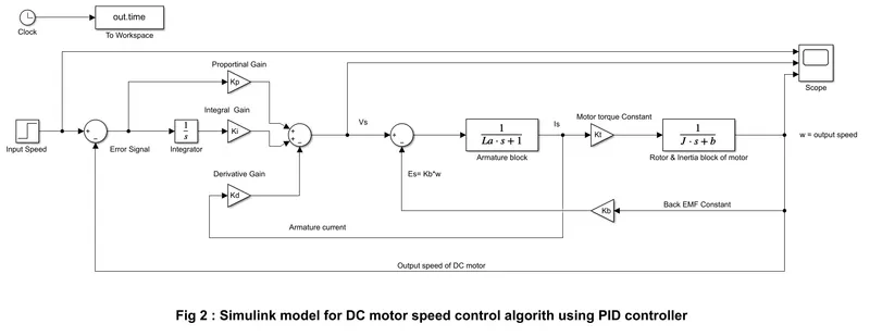
Motor control design with PID controller :
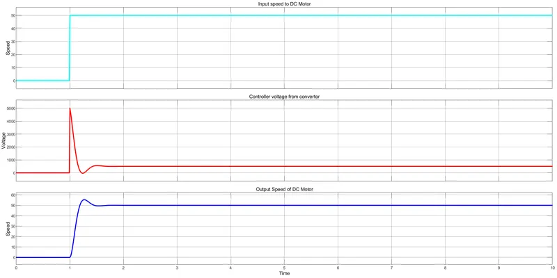
Output graphs / Plots :
Conclusion / Results :
We have successfully design the motor and its cotroller using PID algorithm so as to obtained the results as per project objective. Here Kp & Kd is found out using the pole placement method and ki is set manually till we observe the behaviour of speed is controlled as per input reference speed. Initially for very short time PID converter voltages went to high value then get settled down & similarly output speed got high for small amount of time and then back into the refernce speed. However if we chnage the value of damping constant (zeta) from 0.5 (underdamped) to 1.0 (critically damped) then it was observed that there was no overshoot & settling time almost eliminated.
From above calculations , model design & output plots we can state that the Proportional, Integral, and Derivative (PID) control design knowledge gained in the training to design is achieved & developed a controller to maintain a desired speed for the motor.
Enclosed : script file, simulink model & scope output.