Project-1: Modelling an electric Car with Li-ion battery
Project-1: Modelling an electric Car with Li-ion battery
Aim : Create a MATLAB model of electric car which uses lithium ion battery and suitable motor. Choose suitable blocks from Simscape or Powertrain block set. Implement the vehicle speed control using PI controller and generate brake and accelerator commands. Avoid using readymade driver block for speed control.
Objectives :
1. System level configurations
2. Model parameters
3. Results
4. Conclusion
Introduction : In recent period world has started accepting the the green technology and focused on reducing the pollution made by old technologies. In automotive sector Electric Vehicle is centre of attraction from last four to five years there is surge in EVs and its adaptation by world. Electric Vehicles provide to humanity as a sustainable mode of transport, by not deteriorating the environment. Its been observed that IC Engines provide lot of harmfull gases and degrading our environment rapidly so one of the promising way to reduce this adverse effect is using greener energy thats Electic Vehicles. In fact other reason to consider the EVs is depleting oil reserves worldwide.
This project is completely related to modeling of electric vehicle using MATLAB and its associated libraries. The main focus in this project is to build a Controller using PID block which act as a natural driver and controls the vehicle as per requirement. As discussed main motive is to buid a logic of controller and its complete arrangement so this project is a extenstion of last simulated project named as ''To Create a MATLAB model of electric car which uses a battery and a DC motor'' ( reference link of project details is provided is last section). All parameters related to this EV is considered like aerodynamics, forces, wheels , Kerb weight, power ratting ,battery & other aspects. Although original Nissan LEAF with DC motor.
1. System level configurations :
System level configuation is basic and first step towards designing of an electric vehicle, while designing we must consider the layout means how the system is going to be built and simulate. A block diagram is provided below in figure1 which exactly represents the approach of modeling the EV.
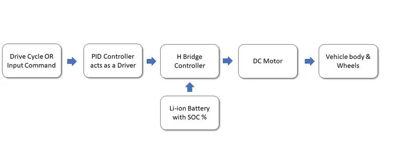
Fig1 - Block Diagram of EV Representing the Blocks at System Level.
The system level parameter would be discussed in detail in section no.2. As it can be seen from above figure an electric vehicle is comprises of following blocks -
- Drive cycle or Input command :- This signal serves the role of actul input command to drive the vehicle like speed or torque requirements.
- PID Controller :- The actual requirement of driving an EV shoud be handles anc control by a specific controller and that work is accomplished by this PID controller which is nothing but a driver giving the commands to vehicle.
- H-Bridge Converter :- To run the motor as per drivers input a converter plays an important role just like here this H bridge provides the signal to motor to run at required speed.
- Li-ion Battery :- Battery is one of the key component of an EV or its a fuel. So this provides the required prower to drive the motor efficiently.
- DC Motor :- It can ressembles to an IC engine of a car. This is the major component in EV powertrain which runs the vehicle as per required conditions.
- Vehicle Body & Wheels :- This is the external structure of an EV with complete aerodynamics and other important factors like wheels. gear mechanisms etc.
2. Model parameters :
To build any model the most basic and important requirement is its design parameter and complete data about the drivetrain,aerodynamics,controller, converters and battery. So to comply this requirement a reseach is done about these factor to get the practical values in fact the data is chosen of actual EV car after studying different research papers and thesis. In this section the parameters of each block is discussed with its complete details to understand how the model is built and run accordingly.
After doing the research we have considered NISSAN LEAF EV with all its technicals, basically this car is pure electric works on battery on motor only. In practice LEAF uses AC Synchronous motor for its propulsion purpose but in our EV model DC motor is going to use which is something contradicory but this issue is resolved by assigning the same technical values to DC Motor with some trial and error methods. We have considered the Nissan Leaf parameters from some reseach papers because it is all practical values to be cosnidered which are provided below.
Nissan Leaf parameters -
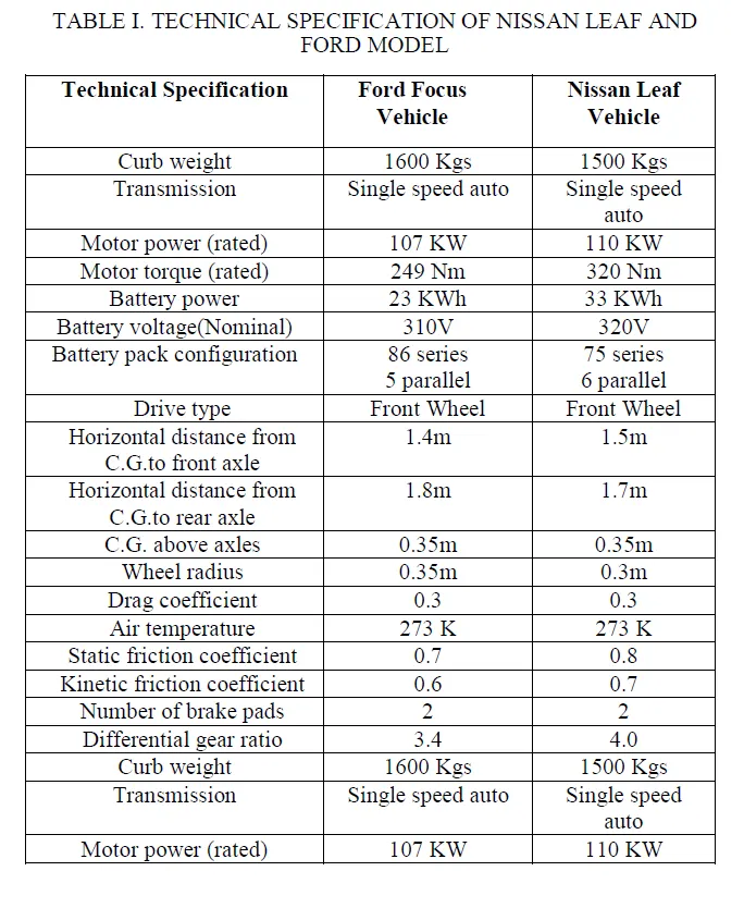
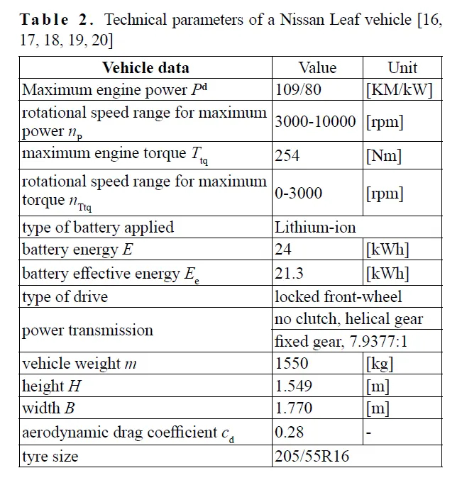
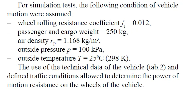
A] Vehicle Body & Wheels : All above parameters are fixed to develop a external body and wheels of an EV model. Here kerb weight, Aerodynamics & wheels technicals are considered. The arrangement and connection of wheels with body, gear and differentials is provided below with the values considered for each blocks.
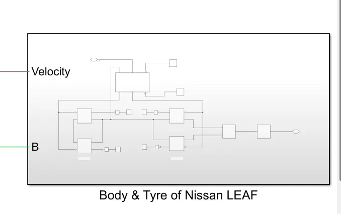
Fig 2- Subsystem Block of Vehicle Body with Wheels
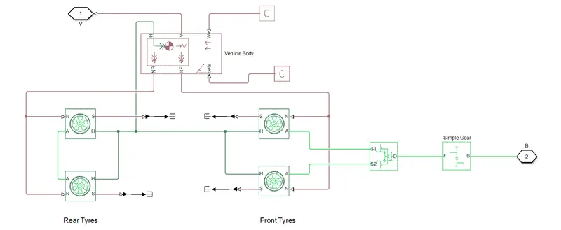
Fig 3- Actual Connection of Vehicle Body with Wheels
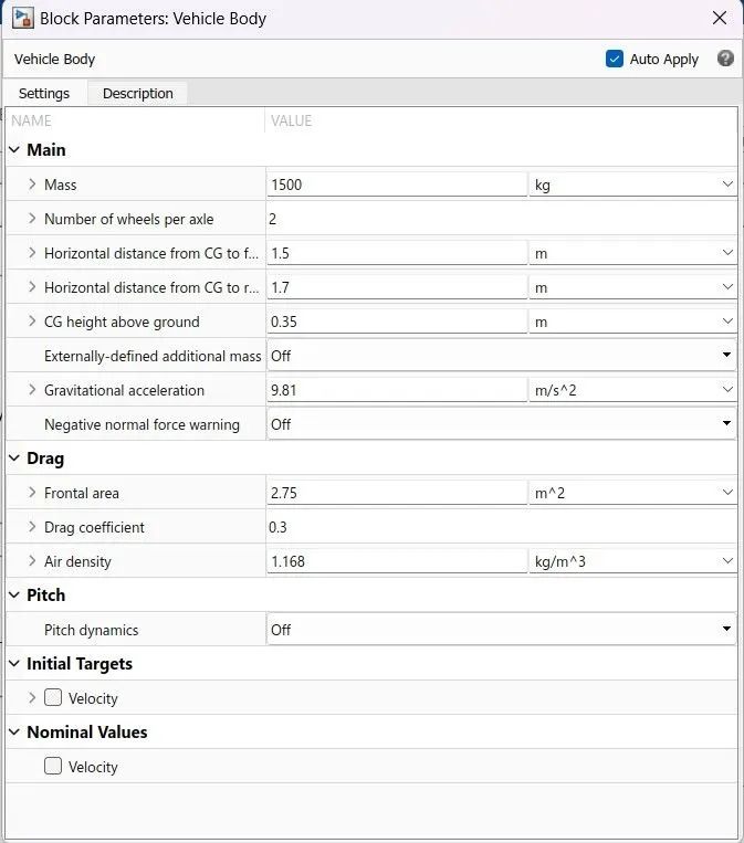
Fig 4- Vehicle Body Block
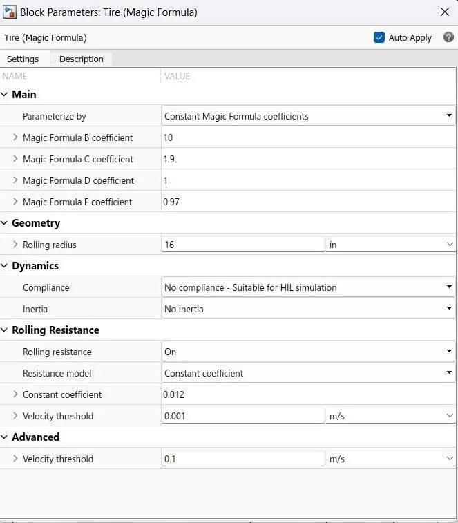
Fig 5- Tyre Block (Magic Formula)
B] PID Controller (Driver) : The key component in this project which is center of discussion is this PID controller block which is operating as a driver. In this controller a typical PID block is used in, which PI configuration is selected as shon in parameter block, which receiving the error signal from input speed or velocity and reference velocity then this error signal fed back to PID block and the output is taken. To decide acceleration & deceleration modes two different saturation blocks are used with positive and negative limits specified. Now to eliminate the algebric error in system a transfer function block is used.
As the system is non linear then auto-tuning of this PID block is not possible so the tuning is done using the identifying new plant and then tune this PID using manual steps. After successfull tuning is done then system will get update with updated values of PI gains. All design and other details are provided in below figures,
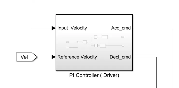
Fig 6- PI Controller Driver Block
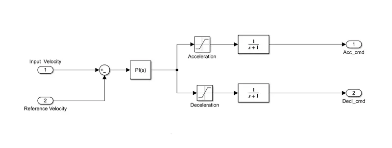
Fig 7 - PI Controller's Internal Arrangement
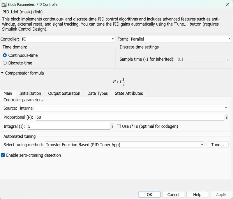
Fig 8- PI Controller Driver Block Parameter
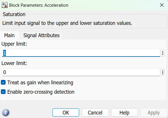
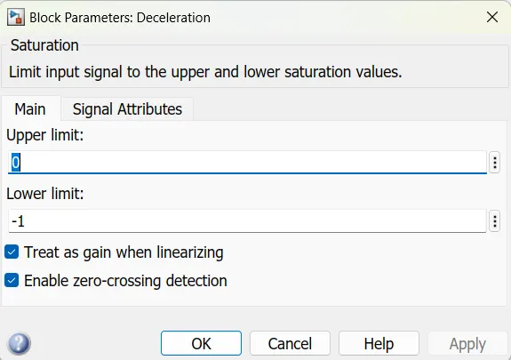
Fig 9- Saturation Block Parameters
C] Drive Cycle Block : Its an input for the vehicle to drive as per the conditions in other words the blocks generates the signals of acceleration & decceleration accordingly. In this case we have choosen NYCC drive cycle to perform the task. This block contains more number of practical drive cycles which are used by most of the reseachers do for checking the vehicle perfomance. Below fig shows drive cycle source block. This New York City Cycle driving cycle is a typical urban driving cycle with average speed of 31.51km/h and has frequent braking and acceleration. Which is perfect fit for our EV experiment & simulation.
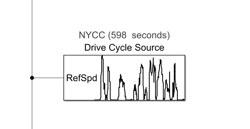
Fig 10 - Drive Cycle Source Block
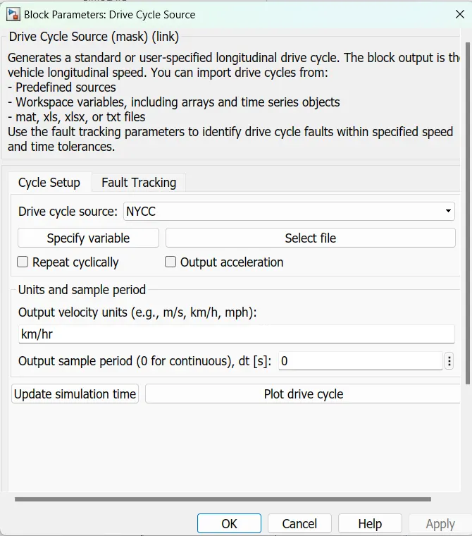
Fig 11- Drive Cycle Source Block Parameter
D] H-Bridge Converter : Another important block is power converter which is used to to boost up the input voltage to level of motor as per its ratting. In this model a DC motor is going to use thats why in this case a H-Bridge converter is used which is a type of DC-DC converter. It is a four quadrant chopper drive block which can work in motoring as well as regenerative mode of motor. This block takes input as a PWM pulses to run and generate the output voltages so thats why this block is combined with PWM controlled voltage source which generates the PWM signal based on the input signals. The H bridge used to deliver the voltage and generate the voltage whne motor is in generating mode. By default input ports are PWM - it is a electrical input signal which taken the PWM signal to get the controlled output, REF - this is a reference input Electrical conserving port associated with the floating zero volt reference , REV- this input is for when the polarities of current or voltage get reversed it comes into picture, BRK - Electrical conserving port associated with the voltage that controls when to short circuit the H-Bridge block output.
The parameters of these blocks are set specific values are shown in below figure which is a block parameters of these devices.
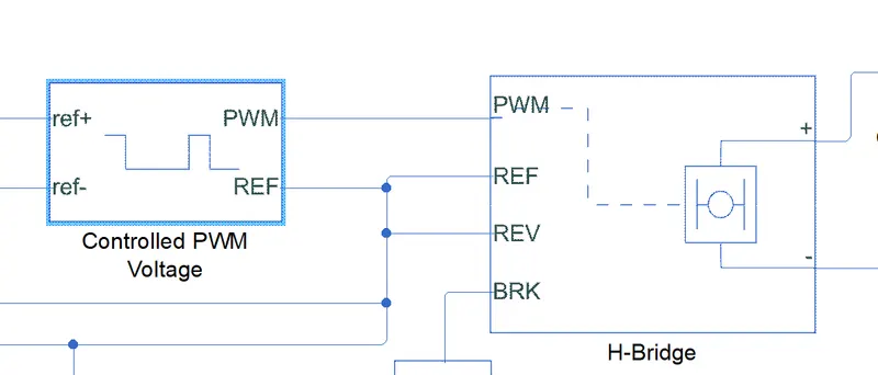
Fig 12- H-Bridge Block with Controlled PWM Voltage
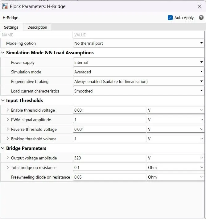
Fig 13- H-Bridge Parameter Block
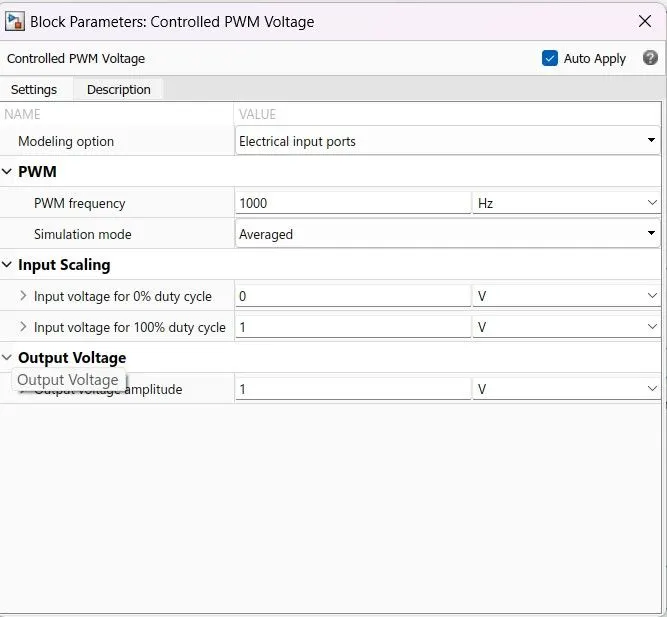
Fig 14- PWM Voltage Block Parameter
E] Li-Ion Battery : As the aim depicts a typical Li-ion battery should be used in this modeling so a a battery block from simulink library is picked for this purpose. It has important in-built topologies so as to perform different important functions like charging, discharging , State of charge percentange etc. also it has option to measure the SOC percentage,voltage & current. So the capacity is retained same as the power ratting of actual nissan LEAF.
The normal battery voltage is kept same as motor rated voltage and H bridge output volatge. Type of battery selected is Lithion-Ion which is actually battery used in LEAF EV and The rated capacity is calculated from below formula
`kWh = ( Ah * V )/ 1000`
So for this model case rated capacity is found as 104 Ah and considered as shown in below figures.
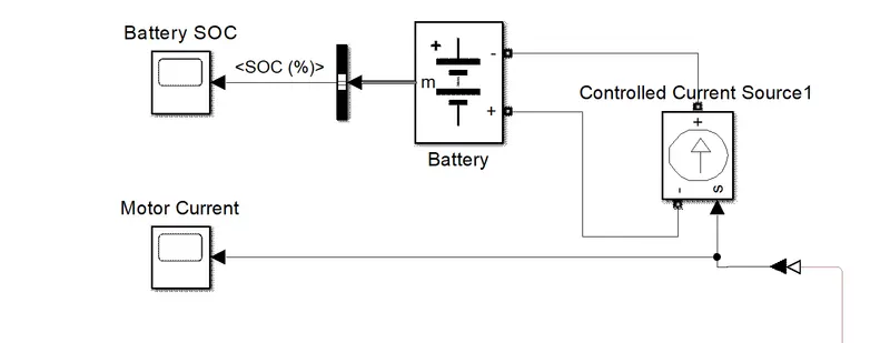
Fig 15- Battery Block
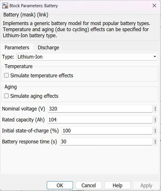
Fig 16- Battery Block Parameter
F] DC Motor : For the designed model of nissan LEAF drivetrain consist of DC motor which is major component in propulsion system. A simple DC motor blcok is selected from simscape library to model the architecture of an EV. So as discussed earlier to get the actual practical performance from this DC motor same as the nissan leaf EV we have considered the parameter as No Load speed @ 8000 RPM , Rated speed @ 7000 RPM & Rotor ineria to 0.01 cm^2*g. Rest all parameters kept at their default values as visible in below fig.
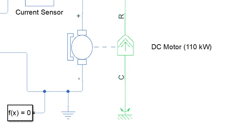
Fig 17- DC Motor Block with 110 kW Power
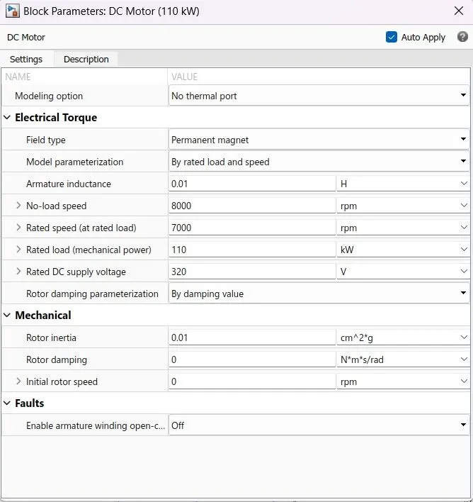
Fig 18- DC Motor Block
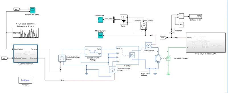
3. Results : The final built model is provided below with complete setup and internal connections. This section contains the result after simulating the model for the specific drive cycle as mention above. All details are provided below with its corresponding information.
Electric Vehicle MATALB Model
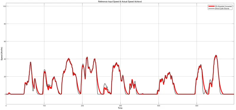
A] Drive Cycle vs Actual speed Plot -
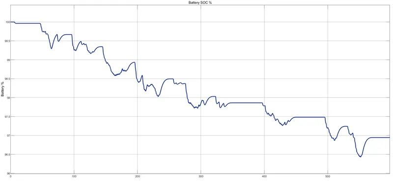
B] Battery SOC Percentage -
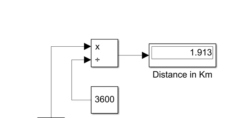
C] Distance Display -
4. Conclusion :
- As the main aim was to build a controller which handles the vehicle performance based on acceleration & deceleration a typical controller is build using PID block. The working of this block is same as actual driver which generates both commands to control the vehicle so it can be concluded that a Controller is built successfully using PID block and proper arrangements of blocks.
- From Drive cycle Vs actual speed plot above conclusion is verfied and it can be observed that vehicle is following the input of drive cycle. Total distance covered is around 2 kms as visible in display block.
- Battery SOC percentage is reduced to around 97% from 100% which is just a small values that is because vehicle only covered 2kms distance so here it can be stated that battery is working with better performance too.
(Note :Enclosed the MATLAB files related to model.)