Final Project: Design of an Electric Vehicle
FINAL PROJECT : Design of an Electric Vehicle ( NISSAN LEAF)
AIM : To Create a MATLAB model of electric car which uses a battery and a DC motor. Choose suitable blocks from Powertrain block set. Prepare a report about your model including following:
Objectives:
1. System level configurations
2. Model parameters
3. Results
4. Conclusion
Introduction : From the last few years Electric Vehicles got quiet popular in Indian market and ovearseas as well. As world is serious about to reduce the emmision of CO2 & other harmful gases which is produced by ICE vehicles so replacement would be EV & its clean working without damaging the environment. One of the most common difference between internal combustion engine (ICE) & electric vehicles are motors and engines, However motors are more powerful and efficent than IC engines. EV are comfortable in driving and in their designs like it has major parts motors,controllers , battery packs & other dynamic uitlities. If motor is well controlled then its easy to get high torque and speed output from motor with overall dynamic control stability. EVs are getting adopted rapidly by consumers due to its low cost of maintainance and fuel saving. These EVs are catgorised into Pure electric vehicle , in which only on source of energy & propulsion is used that is battery and engine & Hybrid electric vehicle, in which motor and ICE both used to propel the vehicle. These are more sub-categorised further depeds on their design and structures.
In this project a EV model is developed using MATLAB/SIMULINK software for NISSAN LEAF EV, all parameters related to this EV is considered like aerodynamics, forces, wheels , Kerb weight, power ratting ,battery & other aspects. Although original Nissan LEAF uses AC Synchronous motor but in our model we have used DC motor by doing AC motor parameter comaprison with DC one and found the results were in order as expected. Apart from these motor all other technical terms are retained as it is from nissan LEAF. H- Bridge converter is used to take input as PWM signals and fed back the motor with requred terminal voltages which will be discussed further. Input speed reuqirement is considered from dirve cycles block to simulate the model. To buid these model and chose parameters different different research papers are studied related to EV , DC motor applivcations , parameters of vehicles body , battery pack etc. and finally done with the project. We shall discuss all the details stepwise in following sections.
1. System level configurations :-
Initially we would be desingning a block diagram of particular electric vehicle (4 wheeler in this case) which is going to be modeled using MATLAB/SIMULINK including powertrain blockset library too. Here practical aspect will be taken into account to design a block diagram as shown in below fig 1. by using this block diagram all other peripheral paramters and required details will be designed or built. Block diagram of repsective EV is provided below
,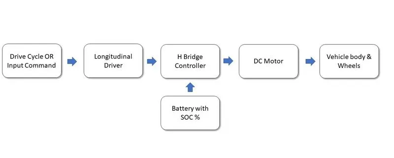
Fig 1 - Block diagram of an Electric Vehicle
From above diagram it seems the power flow or process frow is from left to right which means from drive cycle to vehicle body but in practice we shall work in opposite direction from righ to left just to buit the targetd designs. Initially vehicle body parameters need to be define then DC motor then H bridge , Battery ratting & capacity and so on, Each parameters are going to be calculated to defined in the following manner of process.
Vehicle body & wheels : Here a reference vehicle is consider after checking and studying different thesis & research papers across the globe and experiments done by professionals. In this case NISSAN LEAF which is pure electric vehicle runs on battery & motor without any ICE configurations is considered. Our model consist of 4 wheels and its front wheel drive configuration is opted. The model is buit in MATLAB using SIMSCAPE library as shown below,
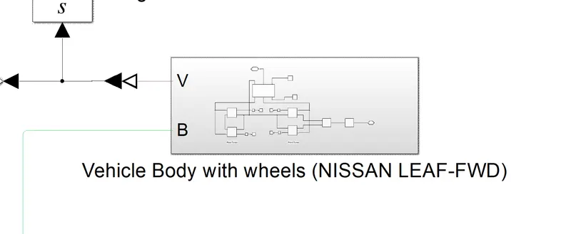
Fig 2- Subsystem Block of Vehicle Body with Wheels
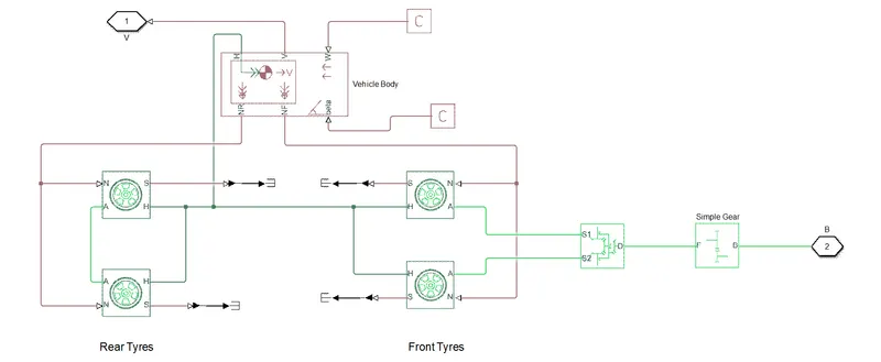
Fig 3- Actual Arrangement of Vehicle Body with Wheels
Above both the figures shows the arrangement of EVs wheels and body arrangement. Four wheels are used with same parameter, which will be discussed in 2nd section, and connected as shown front & rear both wheels pairs are connected to a common hub point with vehicle body. Slips of all wheels are not taken into account to its terminated for all four wheels. Normal force N ports pf both the pairs are connected to vehicle body with rear force NR & fornt force NF ports as shown above, there are physical output sigan of body. Front wheels Axles are connected to differential system and then to simple gear block which is again a physical input signals for the front wheels from motor shaft and rear wheels axles are commoned.
Vehicle body has 5 ports as visible in above fig 3, port V is for velocity of vehicle while running , W is for the wind velocity inputs acting on EV body& beta is for road inclination angle which is a input signa to body . Simple gear set to its default setting.
DC Motor - Nissan LEAF has AC motor as major propulsion unit but in this model DC motor is considered so the parameters of LEAF is compared with DC motor and simulated it to get the desired output however in practice DC motor is not used in EV high power application due to its major issues like high maintainance , low efficiency & large size. A simple DC motor block is used from SIMSCAPE library to used it in the model as shown in below figure,
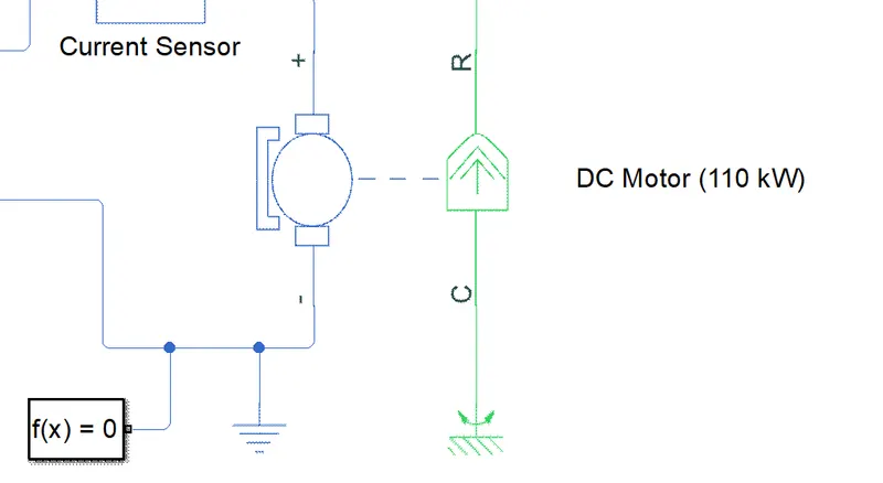
Fig 4- DC Motor Block with 110 kW Power
H- Bridge Converter - As input is DC from battery and the motor that is being used is DC so a DC-DC converter would be ideal for these EV modeling. A simple and powerful converter is used named H Bridge motor driver is used to get the output boosted up from input using its four best in class semiconductor switches.The output of H bridge is controlled voltage depends upon the input PWM signals. It gets on if the input signal has more value that the threshold value and if its not then the block will continue to maintain the load circuit using its internal devices. In simple words this is a four quadrant chopper drive block which can work in motoring as well as regenerative mode of motor. Depending upon the power supply selection it will provide the input and output ports. By default input ports are PWM - it is a electrical input signal which taken the PWM signal to get the controlled output, REF - this is a reference input Electrical conserving port associated with the floating zero volt reference , REV- this input is for when the polarities of current or voltage get reversed it comes into picture, BRK - Electrical conserving port associated with the voltage that controls when to short circuit the H-Bridge block output. The voltage is defined relative to the REF port. A typical block is shown below fig4 which is again part of SIMSCAPE Library .
Controlled PWM Voltage is used to provide a required PWM signal as a input to H bridge. Basically this block resembles a Pulse Width Modulated Votlage source from SIMSCAPE Library, it has capability to take electrical as weel as physical signals as input and based on that it will decide the duty cycle of the output signal. It has two input ref+ & ref- andd two output as PWM & REF, as per the requremet it can be set to PWM or averaged simulation mode. If PWM frequency is high then output will be smoothed.
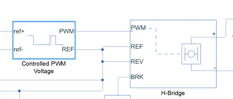
Fig 5- H-Bridge Block with Controlled PWM Voltage
Longitudinal Driver - This driver block belongs to powertrain blockset of MATLAB, its block which has capabilities to generate the acceleration and braking command as of original driver based on the vehicle requirement and input signals provided. It can tgenerates normalized acceleration and braking commands that can vary from 0 through 1. We can use this block to generate the actual commands like driver from inut drive cycles or signals. It has different control methods like PI and other. It contains 3 input ports and 3 output ports as shown in fig 6. The VelRef is input speed command to driver ,VelFdbk is the feedback of actual speed of vehicle, Grade is a angle of gradeability & AccelCmd is a output of acceleration pedal from dirver based on the input fed back this command will generate from 0 through 1 ,Dece;Cmd is the same as acceleration but it acts when driver applies brake.
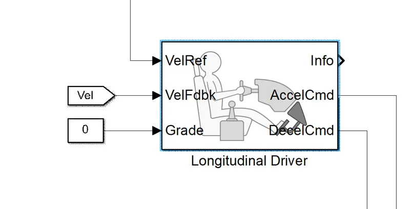
Fig 6- Longitudinal Driver Block
Driver Cycle OR Input Commands - This is Drive Cycle Source block which has many different different types of Drive cycles which is widely used by professionals to perfom vehicle analys depends on the road conditions and other factors. Input can be provided to this EV model either by this block or other blocks like signal builders or by uploding own drive cycle data via excel sheet. This block belongs to Powertrain blockset and the block output is longitudinal speed. Parameters can be set as per the options available in this block and can plot the drive cycle before simulating. Below fig 6 shows drive cycle source block.
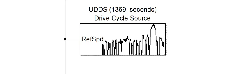
Fig 6- Drive Cycle Source Block
Battery with SOC % - This battery block belongs to SIMULINK Library and it has inbuit standard battery types like Li-ION, Ni-cd, Lead- Acid etc which all are recharegble. Its built using important topologies so as to perform different important functions like charging, discharging , State of charge percentange etc. It allows to set rated voltage , rated capacity , SOC % etc based on these parameters it will automatically computes its discharge parameters. Following fig 7 shows the library block of battery.
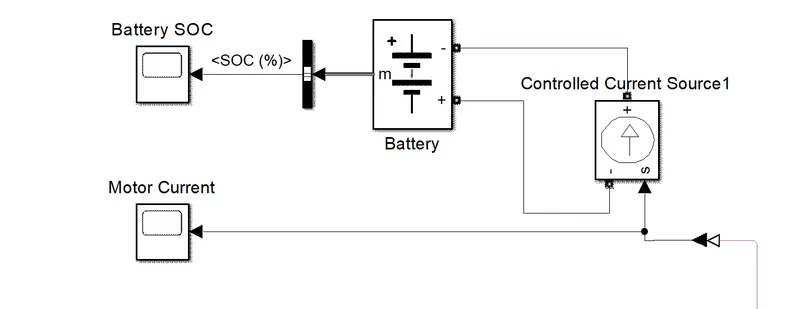
Fig 6- Battery Block
Other Important blocks used -
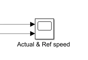
A. Scope - It is used to observe the domain signal coming from respective block. This scope block generally displays the time domain signals. Below fig shows the scope block being used in the model.
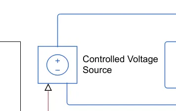
B. Controlled Voltage source - The Controlled Voltage Source block represents an ideal voltage source that is powerful enough to maintain the specified voltage at its output regardless of the current flowing through the source.This block is from simscape library which is shown below
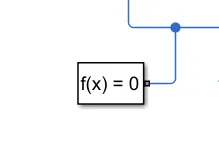
C. Solver - This is important while simulating any simscape blocks as it might have physical signals. The Solver Configuration block specifies the solver parameters that your model needs before you can begin simulation. Each topologically distinct Simscape block diagram requires exactly one Solver Configuration block to be connected to it. It can be connected anywhere to the blocks or connections.
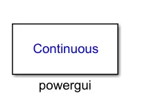
D. Powergui - This blocks helps you to simulate the model using different solving methods like continuos or discrete mode. This is mendatory block to run the simulink model containing simscape blocks , the below figure shows the block,
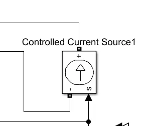
E. Controlled Current Source - The Controlled Current Source block converts the Simulink® input signal into an equivalent current source. The generated current is driven by the input signal of the block. The positive current direction is as shown by the arrow in the block icon. You can initialize the Controlled Current Source block with a specific AC or DC current. If you want to start the simulation in steady state, the block input must be connected to a signal starting as a sinusoidal or DC waveform corresponding to the initial values. Actual block is shown in below fig.
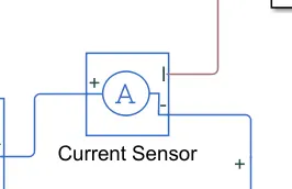
F. Current Sensor - The Current Sensor block represents an ideal current sensor, that is, a device that converts current measured in any electrical branch into a physical signal proportional to the current. The fig below represents the actual block.
G. PS-Simulink Converter - The PS-Simulink Converter block converts a physical signal into a Simulink output signal. Use this block to connect outputs of a Simscape physical network to Simulink scopes or other Simulink blocks. below fig shows the actual block
2. Model parameters :- To get the practical output of built EV model choosing parameters is important step it should be practical values not assumed. In this project the model parameters are selcted after studying the various research papers and thesis experimented by different different professionals over the globe. While chossing all these parameters to built the EV car selection process of parameters were done in parts like from all the research material values for Aerodynamics & wheels , Motor , Converter , Battery and other important inputs of this EV cas is selected accordingly to achieve the desired output. Finally NISSAN LEAF EV is considered with all its technicals, basically this car is pure electric works on battery on motor only. This LEAF uses AC Synchronous motor for its propulsion purpose but in our EV mdoel DC motor is going to use which is something contradicory and this issue is resolved by assigning the same technical values to DC Motor and some trial and error methods. After doing all the trial the output observed somewhat near to the expected results from this model. We have considered the Nissan Leaf parameters from some reseach papers because it is all practical values to be cosnidered as mentioned below,
Nissan Leaf parameters -
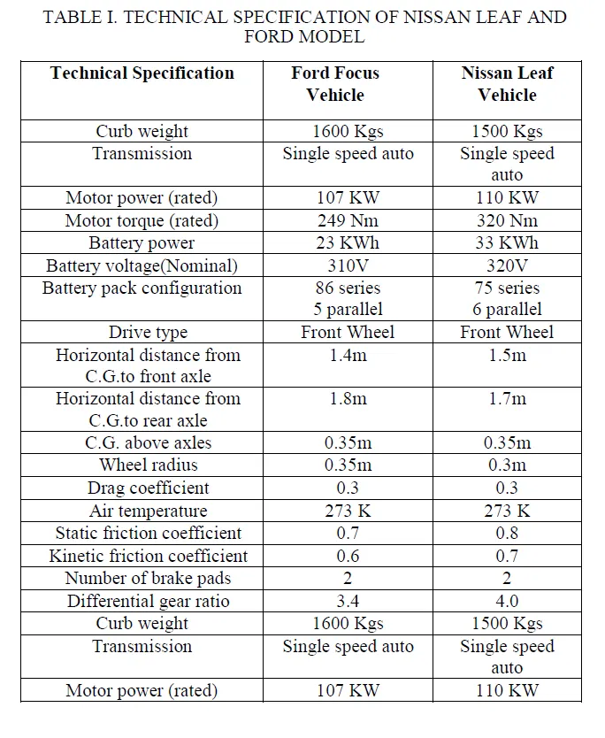
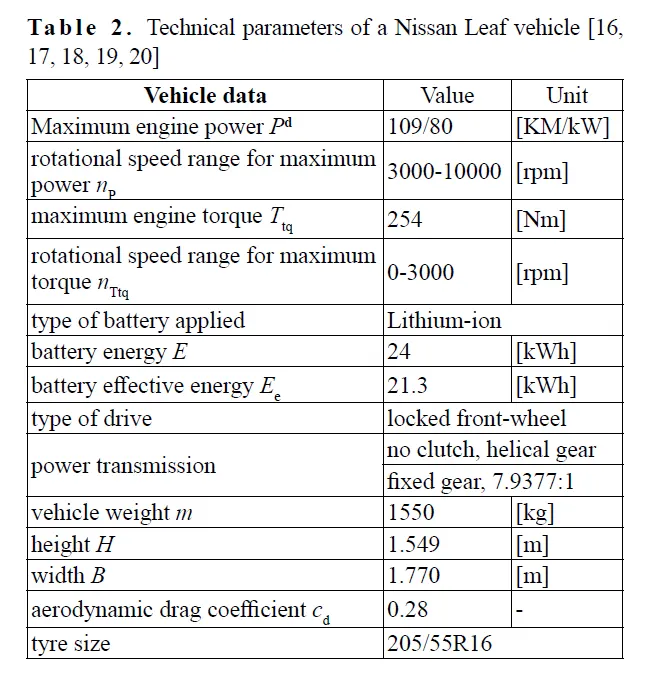
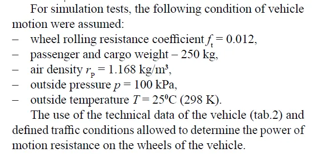
Vehicle body & wheels : From the above tables values for vehicle aerodynamics,vehicle kerb weight and wheels technical details are considered and set in respective blocks of Vehicle body as provided in below figure 7 & figure 8. Only the available details are fixed in these blocks and remaining are kept as default values as mentioned in provided figures and their connections are done accordingly as explained in privioous section.
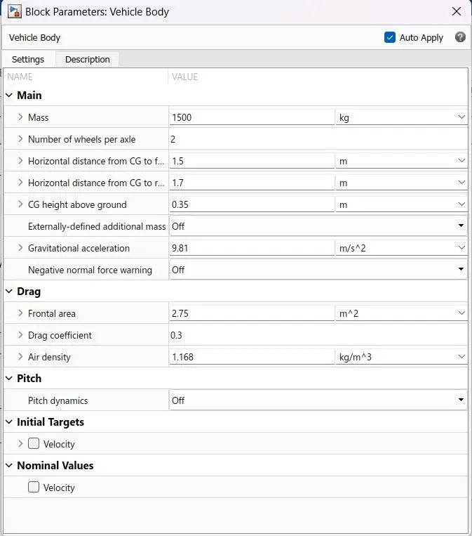
Fig 7- Vehicle Body Block
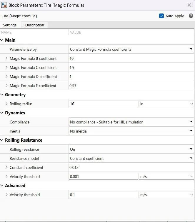
Fig 8- Tyre Block (Magic Formula)
DC Motor - Here a simple DC motor block is used and its parameters are set as per the nissan leaf's AC motor capacity initially then run the model however the results were not satisfactory so some parameters needed to be changed by doing the trial and error method. So after attempting different different values finally the results got somehow near to desired output by fixing the values of No Load speed @ 8000 RPM , Rated speed @ 7000 RPM & Rotor ineria to 0.01 cm^2*g. Rest all parameters kept at their default values as visible in below fig 9.
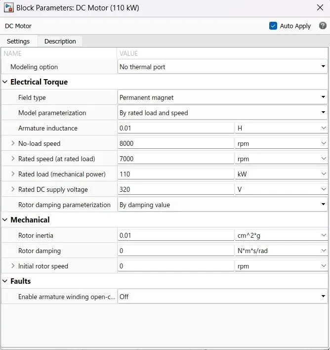
Fig 9- DC Motor Block
H- Bridge Converter - For this Converter block the parameter are set as mentioned in below Fig 10. It set to internal power supply so that internal devices can use the same internal power, simulation mode is chosen as averaged because the input we are giving here has more time consuming so the average mode will run fatser and simulation results will get better. Regenartive braking is also selected with smoothed load characteristics. Threshold voltages for forward and reverse conduction is set to minimum values and PWM amplitude is 1 volt. Output voltage is set as rated voltage of DC motor keeping rest factor to their default values.
Controlled PWM Voltage block provides the input pulse in the form of voltage signal with parameter set to particular values as provided in fig 11 by keeping frequency high to get the smooth output waveforms.
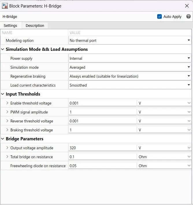
Fig 10- H-Bridge Parameter Block
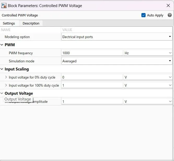
Fig 11- PWM Voltage Block Parameter
Longitudinal Driver - For this block all values are kept default but only the reference velocity unit changed to Km/hr as we are driving or accelerating the EV Car in Km/hr speed. This same consideration is made with input signa too. This block works on th PI algorith and done its job to behave as actual driver by producting the accelerating and braking commands. The block parameter is shown in fig 12.
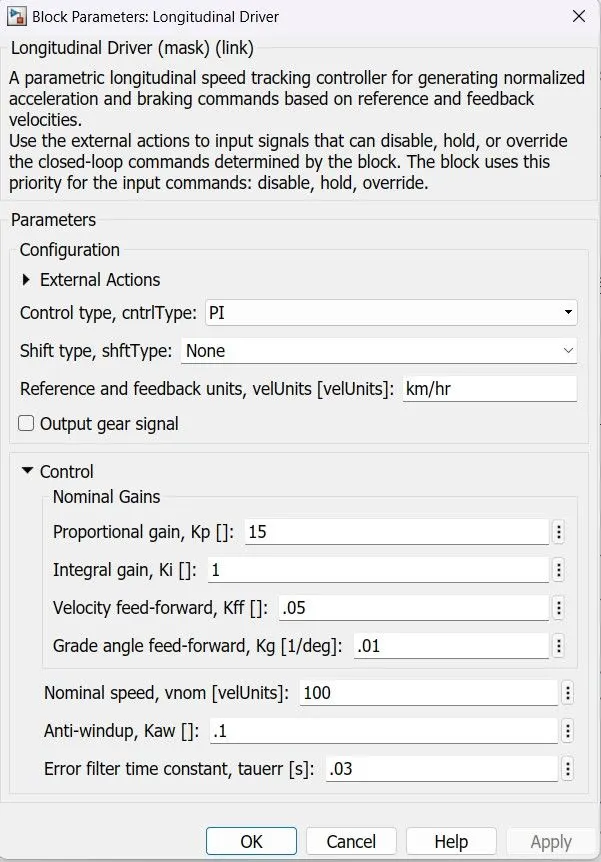
Fig 12- Longitudinal Driver Block Parameter
Driver Cycle OR Input Commands - As EV car is developed to serve the purspose of daily commute of any indivisuals and this are the practical scenario we had considered. So to achive these desired task this EV should be given input which has characteristcs or daily commute either by preparing own input in excel sheet / singal builder or by provding the drive cycles. In this case we have considered drive cycle named Urban Dynamometer Driving Schedule (UDDS) driving cycle is a typical urban driving cycle with average speed of 31.51km/h and has frequent braking and acceleration. Which is perfect fit for our EV experiment & simulation. So the parameter selected for drive cycle via the Drive cycle source block and parameter are mentioned in below fig13.
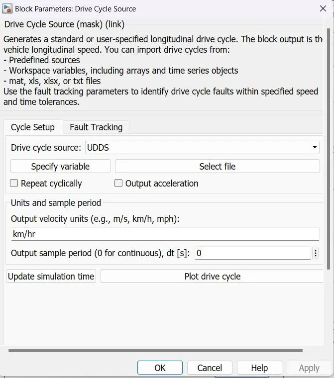
Fig 13- Drive Cycle Source Block Parameter
The UDDS Drive Cycle plot is shwon below which has steep acceleration & deceleration behavior which enables us to check the performance of this model as per the desired requirement. The below fig shows the actual UDDS cycle plot which is speed vs time plot in km/hr total time of this drive cycle is 1369 seconds with around distance 12.26 kms.

Battery with SOC % - The battery pack values and capacity is retained from the actual data mentioned above earlier. The normal battery voltage is kept same as motor rated voltage and H bridge output volatge. Type of battery selected is Lithion-Ion which is actually battery used in LEAF EV and The rated capacity is calculated from below formula
`kWh = ( Ah * V )/ 1000`
So for this model case rated capacity is found as 104 Ah and considered as shown in below fig 14. This battery block has inbuild fuction to check the state-of-charge of battery percentage , current & volatge and has other different battery type options which allows us to perform experiments as per requirement.
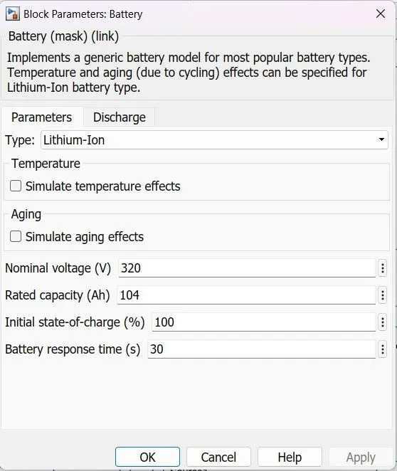
Fig 14- Battery Block Parameter
3. Results :
The results are obtained after simulating the all parameter which discussed till now by connecting them in a proper manner to confugure a proper Electric Vehicle MATLAB Model using different library blocks. A main schematic arrangement is represented below fig 15 which has all the blocks connected with all parameter values setted.
Electric Vehicle MATALB Model :
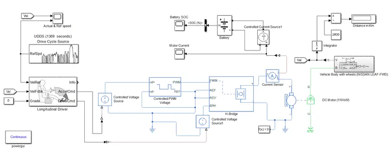
Fig 15- Complete Schematic of a Electric Vehicle using MATLAB ( Nissan LEAF)
A] Drive Cycle vs Actual speed Plot -
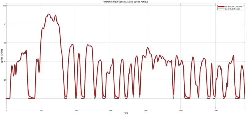
Fig 16 - Scope output of Drive Cycle Vs Actual Speed of EV
B] Battery SOC Percentage -
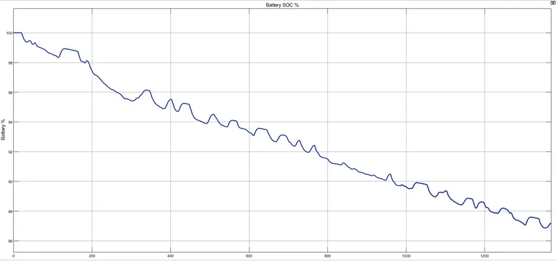
Fig 17 - Scope output of Battery SOC Percentage
C] Motor Current -
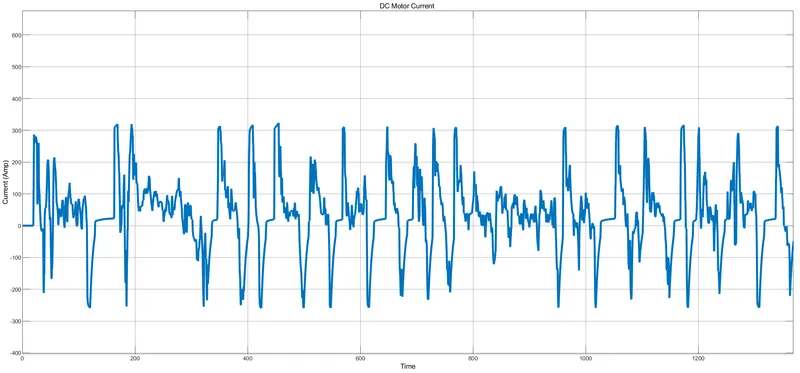
Fig 18 - Scope output of Motor Current
D] Distance Display -
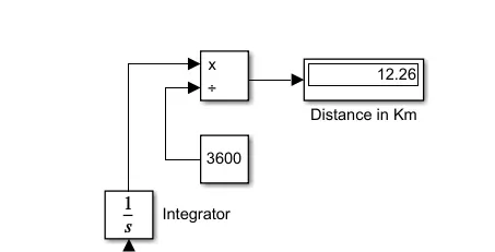
Fig 19 - Display Output of Distance covered in Km
4. Conclusion :
As the main objective is to build a electric vehicle model using MATLAB/SIMULINK and its other associated libraries like powertrain Blockset & Simscape Library so this objective is achieved and conclusion can be drawn after observing the performance and output of this model as -
- The EV car model is following the input commands of driver block this can be observed in scope output fig 16. The input signal marked in black color is followed by the vehicle model which is marked by red color line so it is okay to conclude that built model is performing satisfactory like actual electric vehicle for the acceleration and deceleration commands dropped by driver. Actual distance covered by the vehicle for one UDDS cycle is 12.26 kms in 1369 seconds.
- While steeper deceleration vehicle could not able to reach the zero speed which is due to some back emf or opposing force generated by DC motor and other reason behind it is that the actual LEAF model is build with AC motor and here we have taken DC motor without exact ratting/parameters designs.
- Battery performance observed quiet good, after running one UDDS cycle battery soc % fallen from 100 % to 87.20 %. Battery got discharge while acceleration and recharged during the brake or deceleration of vehicle which means model is performing excellent in motoring & regenerating regions.
- Motor Current observed with both the polarities means when vehicle is running with acceleration command current was positive and when its braking current observed negative means motor was acting as DC generator while braking.
- Finally, after studying all the output & sumualtion data it can be concluded that electric vehcile car model is built in order to perform the respective tasks and can be stated that its a actual electric vehcile MATLAB Model using DC Motor & battery as per the aim.
References -
- Wawrzyniec, G. (2016). Theoretical Analysis of the Effect of Traction Parameters on Electric Vehicle Energy Consumption and Driving Range. TEKA. COMMISSION OF MOTORIZATION AND ENERGETICS IN AGRICULTURE – 2016, Vol. 16, No. 1, 5–12.
- Tomar, V., Chitra A, Krishnachaitanya, D., Raghavendra Rao N S, Indragandhi V, & Raziasultana W. (2021). Design of Powertrain Model for an Electric Vehicle using MATLAB/Simulink. 2021 Innovations in Power and Advanced Computing Technologies (i-PACT).
- Feyijimi Adegbohun, Annette von Jouanne, Ben Phillips, Emmanuel Agamloh, & Alex Yokochi. (2021). High Performance Electric Vehicle Powertrain Modeling,Simulation and Validation. Energies 2021, 14, 1493. https://doi.org/10.3390/en14051493.
- Mohanad Abdulhamid, & Towett Festus. (2022). Design of Pulse Width Modulation Based DC Motor for Electric Vehicle. Journal of Siberian Federal University. Engineering & Technologies 2022 15(2): 162–176.
- Kusum, & Chetan Parveer. (2018). Design of Electric Vehicle. International Journal of Advanced Engineering Research and Science (IJAERS).
(Enclosed all files of model including scope outputs)