Week-7 Challenge: DC Motor Control
Solutions :-
Q1)
A. Explanation of MATLAB demo model named ‘Speed control of a DC motor using BJT H-bridge’ :-
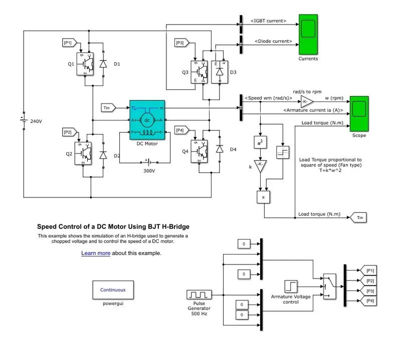
Fig1 - Model of Speed control of a DC motor using BJT H-bridge
Above fig1 shows the demo model of Speed control of a DC motor using BJT H-bridge. We shall discuss its working in details with all operation modes.
Discription of Model -
The Bipolar Junction Transistor (BJT) when used for power switching applications, operates as an IGBT. When it is conducting (BJT operating in the saturated region), a forward voltage Vf is developed between collector and emitter (in the range of 1 V). Therefore, the IGBT block can be used to model the BJT device.
The IGBT block does not simulate the gate current controlling the BJT or IGBT. The switch is controlled by a Simulink® signal (1/0). The DC motor uses the preset model (5 HP 24V 1750 rpm). It simulates a fan type load (where Load torque is proportional to square of speed). The armature mean voltage can be varied from 0 to 240 V when the duty cycle (specified in the Pulse Generator block) is varied from 0 to 100%.
The H-bridge consists of four BJT/Diode pairs (BJT simulated by IGBT models). Two transistors are switched simultaneously: Q1 and Q4 or Q2 and Q3. When Q1 and Q4 are fired, a positive voltage is applied to the motor and diodes D2-D3 operate as free-wheeling diodes when Q1 and Q4 are switched off. When Q2 and Q3 are fired, a negative voltage is applied to the motor and diodes D1-D4 operate as free-wheeling diodes when Q2 and Q3 are switched off.
Main Key Components -
- BJT - If we use BJT for when power switching applications then operates as an IGBT.
- DC Motor - 5 HP 24V 1750 rpm
- Diodes
- Pulse Generator - 500 Hz frequency tuned
- Demux , Bus selector , scopes , gains , switch etc.
Simulation -
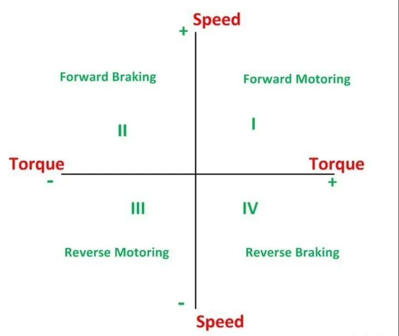
1st Quadrant operation,
- When supply is connected to the system chopper ( IGBT/BJT) Q1 will operate & Q4 will ON and current is goint to be pass from Q1-DC Motor ( R, L , Eb) - Q4 path. If Q1 made OFF then the stored current in inductor will start circulating through Q4 & D2 diode so that it can eliminate the high potential accross the inductor and to save it from failure.
- In first case voltage and current at LOAD ( DC Motor) have positive sign or nature, while discharging the current is again following the same path as in first case ( clockwise path). So here we can say current & Voltage is positve then this is 1st Quadrant operation of chopper.
- This is forward motoring operation.
2nd Quadrant operation,
- When chopper Q2 is ON then the current from Load will start circulating in DC Motor-Q2-D4 path in which voltage potential is same with postive polarity but current direction is anticlock wise. Similarly when Q2 is OFF then the current start flowing through DC Motor-D1-D4 path.
- In this case of operation the volatge has positive polarity but current is negative so this is the 2nd quadrant operation in which voltage found to be postive & current is negative.
- This is forward braking operation.
3rd Quadrant operation,
- In this case of bride operation the copper ( IGBT/BJT) Q3 is operated & Q2 is ON, thus when connected to DC supply the current will follow the Q3-DC Motor-Q2 path. In this case the current having negative polarity will start flowing the stated path and voltage polarity also opposite to that of input voltage so it has negative polarity too.
- When Q3 is OFF then the current stored in inductor start flowing through Q3-D4-DC motor path. As in 3rd quadrant operation we consider the current path opposite so here current is also negative hence this is a 3rd quadrant operation.
- This is Reverse motoring operation.
4th Quadrant operation,
- This is last mode of model operation, in this case the copper Q4 is operated and current flows through the DC Motor-Q4-D4 path. In this case current is flowing in clockwise direction with positive polarity. When Q4 is OFF then the current follows the DC Motor- D3-D2 path with negative voltage polarity.
- So in this case volatge is negative and current is positve so this is called the 4th quadrant operation of model.
- This is Reverse Braking operation.
5. Other process -
- This simulation is operated for 1-2 sec in which speed control is observed of DC motor.
- Chopper current is check for Q3 (IGBT/BJT) via bus selector and scope. similerly for diode D3 the current is checked via bus selector and scope.
- From motor M terminal the speed and armature current is observed with same topology discussed above and torque is calculated from speed using the formula `T=K*(w^2)` .
- P1,P2,P3,P4 pulses are genarated by using pulse generator and fed back to Q1,Q2,Q3,Q4 respective to triger the choppers.
- By observing the motor speed, armature current and load torque we can anayze the speed control of DC motor H-bride using the BJT.
Output/ results : The fig 2 shows the output waveforms of speed, amrature current & Torque.
B. Comments on the armature current shoot-up from the scope results :-
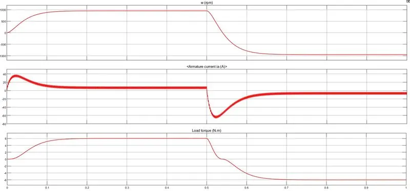
Fig2 - Scope output of DC Motor with duty cycle 75%
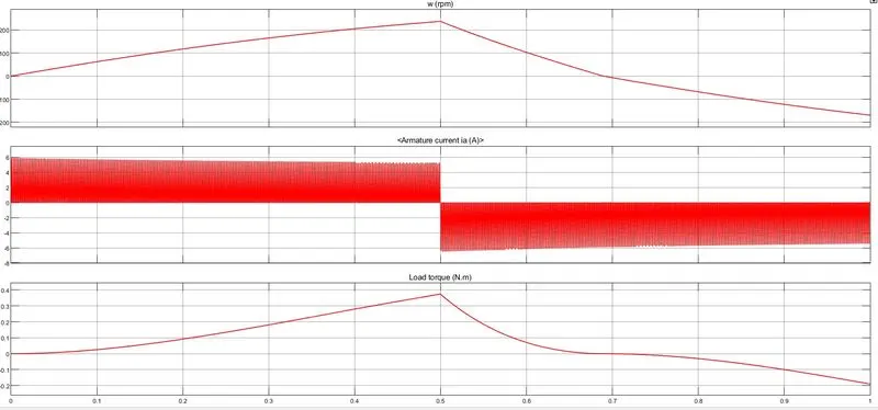
Fig3 - Scope output of DC Motor with duty cycle 35%
Comments -
- From above scope output window the 2nd row is for Armtaure current of DC motor. In which it can be observed that while starting the motor it went high till 40 amps and then reduced or settle around 5-8 amps. After 0.5 sec it went drastically negative and then came back near to zero.
- From waveform it is clear that when motor is operating in forward motoring the armature current goes high even at the time of starting the back emf & armature resistance is low so it could be one more reason for current shoot up.
- in forward braking opering the current goes towards zero and after t=0.5 secod motor operating in reverse motoring region (regenrative braking) in which current again dropped to negative value. After this current may observed reaching towards zero in reverse braking mode which is not shown in above both figures.
- If Duty cycle is reduced to 35% then suddent shoot up in current is reduced which is shown in figure3. Torue and speed also observed the linear increase which means if we increase the duty cycle gradually then this sudden shoot up in armature current can be reduced and desired speed can be achieved.
- Duty cycle , simply means the ON time of waveform which is in percentage. In this case 75% of time choppers were ON which means 75% output voltage will occur in sudden manner. If we supply suddent high voltage to DC motor then armature current will also high hence to limit this current in proper way we have to give duty cycles in increasing manner.
C. Comparison of The Four-Quadrant Chopper DC Drive (DC7) block with the H-bridge model :-
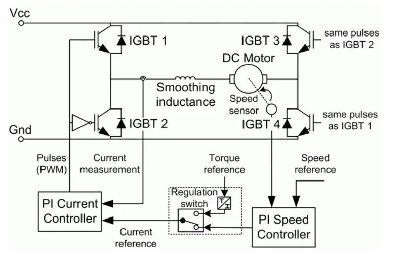
Fig 4- DC7 Block internal configurations
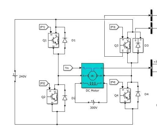
Fig 5 - H Bride BJT Block
DC7 Block -
- As shown in fig 4, DC7 block is a comple DC drive including motor & converter together. Eventhough this is a close loop system & this drive works in all four quadrants
- Here No field votlage is given as a input by default it is fixed to setady state value & IGBT having high switching frequency swiches are used.
- In this DC7 drive the armature current is found to be smooth due to addition of smoothing inductor in series with motor.
- The outputs are obtained with fixed time topology of Discrete with time period of 1e-3 seconds.
- Speed control is done by PI current controller fed backed by PI speed controller which take input of reference speed along with torque at regulation switch. All of these controller outputs are multiples of current sampling time.
- Armature voltage is provided by IGBT converter controlled by two PI regulators to achieve the speed control of DC motor.
- During working the PI current controller is determined the copper duty cycle for requsted armature current, and then this duty cycle is comapred with sawtooth carrier signal to generate required PWM signal for choppers.
BJT H-Bridge -
- As shown is above fig 5, BJT H-Bridge condiguration is highlighted which is open loop system with four quadrant operation.
- Four BJTs is used in the form of IGBT as application is of high frequency applications with antiparallel positions.
- This H-bridge is operated for all four modes like , forward motoring , forward braking, reverse motoring, reverse braking but this is not any kind of drive. Controller topology is diffferent from motor.
- Here DC motor is used with separated field excitation voltage unlike DC7 drive.
- Armature voltage is varied or controlled using the duty cycle but here no feedback loop is used so there is not comparison between armature current and duty cycle with sawtooth singal to get the desired PWM signal which can be fed to choopers.
- We can choose load torque or Speed as input to motor and measurement port will give the singals of speed and armature current.
Q2) Model of 2-Quadrant chopper using simulink :-
2-Quandrant chopper - This copper is also called as type C chopper. In this copper two different comibination of type A & type B is used which both operates in 1st & 2nd quadrant respectively.This basically means that, the power can either flow from source to load or load to source in this chopper. This type of chopper confirguration is used for motoring and regenarative braking applications. Below fig represents the schematic of type c ,
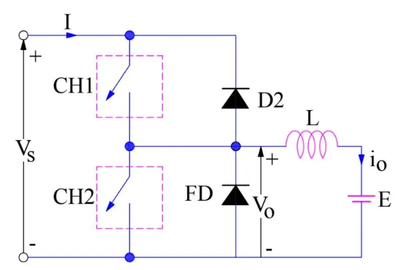
Fig 6 - Type c or two quadrant copper
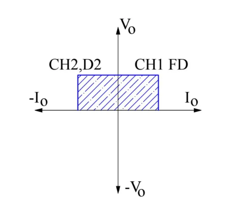
Fig 7 - two quadrant values of V & I
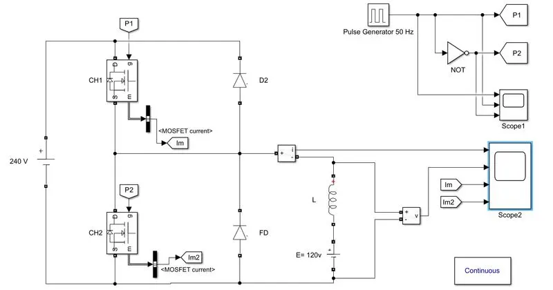
From above theoretical diagram matlab model is build using sumulink library. Here parameter are kept default except below ones,
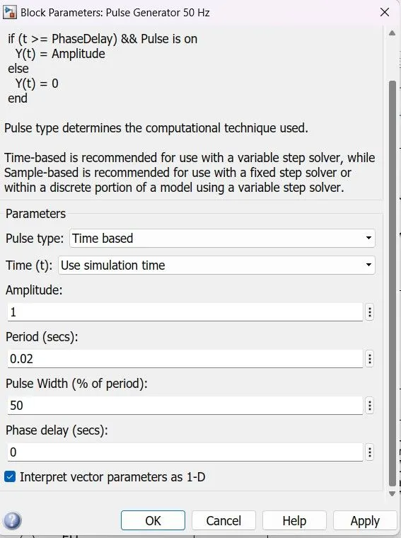
- Pulse generator with 50 Hz frequency and time 0.02 sec
- Load Inductor`L = 9 muH`
- Duty cycle 50%
- Input voltage = 240v
- Load dc voltage = 120v ( 50% duty cycle)
MATLAB Model :
Pulse Generator :
Output waveforms of scope :
a) Scope 1 -
b)Scope 2 -
Explanation :
- Above model is built by considering simple theoretical diagram of 2 quadrant chopper by using MOSFET Chopper /switches CH1 & CH2.
- Here we should not that CH1 & CH2 should not made ON at once beacuse of short circuit issue so to eliminate this condition both are activated at different time using gate pulses.
- Pulse generator is used to provide gate pulses to CH1 & CH2 , as shwon in fig amplitude is 1 & 0.02 time period which is 50 Hz frequency.
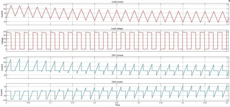
- When supply is given the CH1 is ON and current flows from source to load in positive polarity and stores the energy in inductor. after CH1 is OFF then the stored energy in inductor is release via freewheeling diode FD which is connected across the load. In this manner quadrant 1 operation get completed with positive voltage & current.
- When CH2 is ON then the load behaves as source and current start flowing in negative L-CH2-load path with opposite polarity that of 1st case. After CH2 turned OFF then the current get discharged via diode D2. This is called 2nd quadrant operation in which current is negative and voltage is positive.
- CH1 current is observed positive when CH1 is ON & CH2 current is negative when CH2 is ON.
- From SCOPE1 output waveforms it is obseved that current is initially postive and then negative and following the same behaviour further which means it is operating in both the quadrants. In case of voltage it having only positive polarity while operating in both the quadrants.
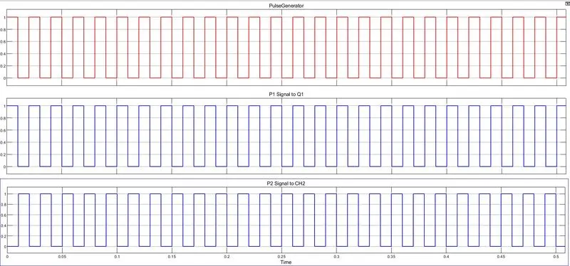
- The SCOPE1 output waveforms are of input gate pulses, from these waveforms it can be stated that when input pulse generator pulses are 1 ( means at their amplitude value) the CH1 is operating as these pulses goes 0 then CH2 gets operated. In this manner two quadrant operation is achieved.
Reference -
- https://electricalbaba.com/class-c-or-type-c-chopper-explanation/
- Power Electronics by Dr. P.S Bimhra ( page no 256)
Q3) Brief about operation of BLDC Motor :-
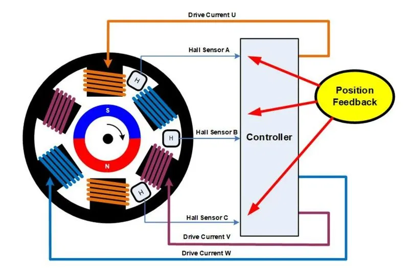
Fig 8 - BLDC Motor construction schemtic
Some Brief about BLDC Motors :
- BLDC Motor stands for Brushless DC Motor which actually require a three phase supply that is by default AC supply for its working or sometimes DC supply depends on application of motor. Unlike conventional DC motor it does not have any Brushes & commutator arrangement.
- In this motor permanant magnets are used on rotor (moving part) and fixed poles wound by conductors which are separated from each other in typical manner as shown in above figure. These phases may marked as A-A' , B-B' & C-C' which forms North & South poles electromagnetically.
- If supply is provided to one of the phase then electromagnetically poles will get formed N&S and it will start attracting the S&N poles of rotor which results into movement of rotor, Similerly in this way all three phases will received the supply and poles will form and rotor captures the speed.
- There is one challenge that how motor know when to activate phase in such a way that motor will not stop ? so answer is controller along with ahll sensor do their work by monitoring the electromantic flux around the poles and activating the respected poles to have continous rotation of motor.
- There is one more important point to overcome the low power of BLDC motor. Converter will energize the two different phases/ poles of stator in such a way that one pole will attract the rotor and another one will repel the same pole of rotor which results into more torque and speed .
- This motor has the cosntant torque characteristic like DC motor thats why its named as BLDC motor.
- Its has two types 1. Out runner (Outerrotor type) & 2. Inrunner (Inner rotor type)
Reference - https://www.monolithicpower.com/en/brushless-vs-brushed-dc-motors