Final Project: Electric Rickshaw modelling
Final Project : Electric Rickshaw modelling
Aim : Create a detailed MATLAB model of an electric rickshaw (three wheel passenger vehicle) as per details below:
- Rear wheels driven by PM brushed type motor.
- Assume efficiency points of motor controller and motor.
- Make an excel sheet of all input and assumed data.
Results: For any three standard driving cycles show energy consumption, temperature rise of motor and controller for 100 km constant speed driving at 45 kmph.
Objectives :
1. System level Data /Assumptions.
2. Model Parameters.
3. Results
4. Conclusion
Introduction :
One of the major issue whole world facing is pollution and its becoming important concern to worry about. Just like light motor vehicles, the commerical vehicles , passenger vehicles etc uses the IC engine which produces same CO2 emmission. Auto Rickshaw's are quiet poppular in passenger vehicle categories in india as well as most oof the asian regions which serves as taxi's to carry people or a goods carrier vehicles, specially in india. These three wheeled vehicles play the most important role as public, private and para-transit modes of transportation and they are suited to the Indian traffic environment.
Instead of using IC engine it can be replaced by pure electric drivetrains same as EV cars which helps to conquer the hazardous issue of pollution and infact the electric motor has efficiency around 95% whereas the IC engine are 30% efficient. Late in 2010s a typicall eletric rikshaw was introduced by china then it came to india around 2011 started gaining popularity. Initially industries where developing small light weight e-rickshaws but in last 2-3 years electric vehicles gained its pace in india as well as overseas. Now major automobile contendors like BAJAJ, MAHINDRA, PIAGGIO, KINETIC etc started introducing their Eletric Auto Rickshaw in indian market and gaining so much hipe.
So in this project we are modeling the '' BAJAJ RE Electric Rickshaw'' all the specification of this model is taken from their official website and calculated the required details. Some assumptions areo made in order to get the results also referred to much research papers and projects done by industry proffesionals so finally a model is build and simulated to the specific conditions which are discussed below in depth.
1. System level Data /Assumptions :-
In the project as discussed BAJAJ RE Electric Rcikshaw is considered and all the actual data is taken into account to built a MATLAB model using the Brushed DC motor , HH-Bridge power converter, Longitudinal driver , vehicle body , wheels and other important blocks. To build any model or system the basic and most important factors are the practical data and information. Before going with final modeling a basic overview of e-rickshaw should be understood means how the model needs to be build and what are the factors associated with it, this is explained in below block diagram with architecture of E-Rickshaw's components,
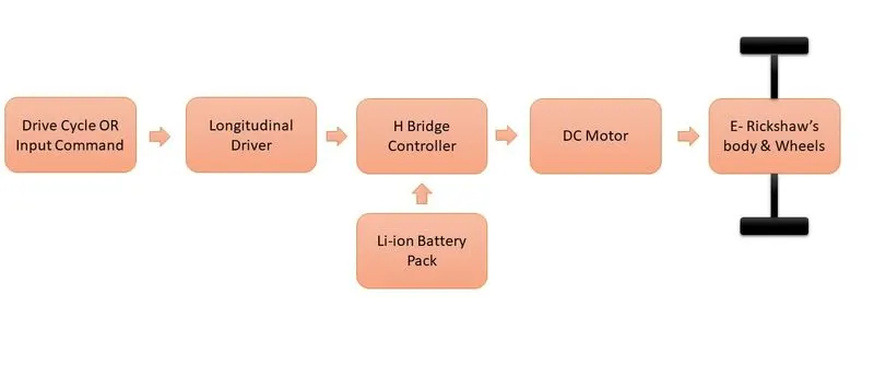
Fig 1- Block diagram architecture of E-Rickshaw's components.
From above block diagram its quiet easy to understand the actual arrangement of componets and devices within the model & flow of energy from one system to other one. Now we shall declare the actual specs of this bajaj model and the factors which are assumed to build this model in MATLAB. By considering these parameters the model is developed and simulated to achieve the required results.
List of Assumptions :
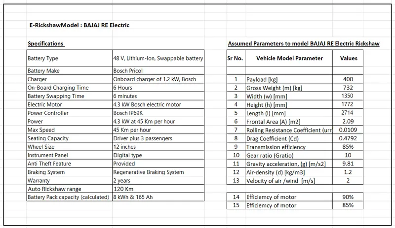
Fig 2 - Table of Assumptions
2. Model Parameters :-
In this section we shall share the details about the each and every blocks used in this model and specify their parameters used. This will be discussed in following order-
- Body and Tyres Arrangement (aerodynamics)
- Drive Cycle or input signals
- Longitudinal Driver
- H-Bridge Power Converter
- DC Motor
- Li-ion Battery Pack
- Other Miscleneous
All above blocks are discussed with their complete configurations and values used during the simulation, So lets start with first arrangement.
1] Body and Tyres Arrangement (aerodynamics) : The actual block of this e-rickshaw is shown below in fig 3 which is having vehicle body block connected in proper sequency with rear two wheels and front wheel of autorickshaw. This e-rickshaw is rear wheel drive and those wheels are connected to motor's shaft via differential & gear system.
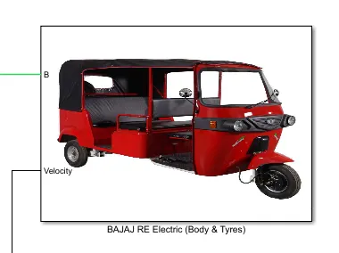
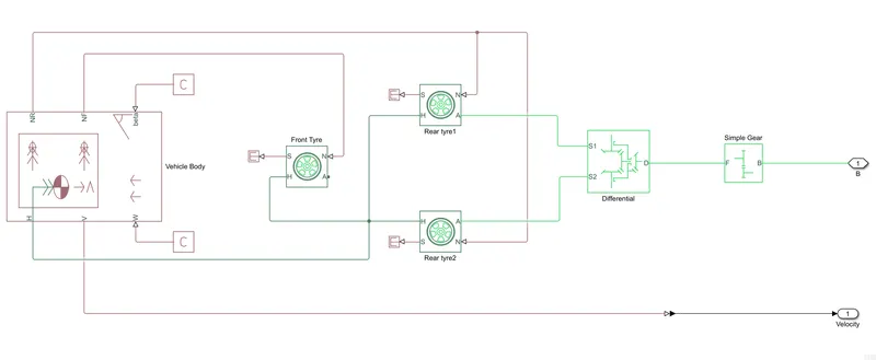
Fig 3 - Block diagram & actual arrangement of Body and Tyres
Above figure depicts the precise connection of vehicle body and wheels. The vehicle body block from simscape library is used and magic tyre formula block to serve the purpose of tyres. The values or parameter of each of these component is provided in fig 4 & fig 5 as shown below. These are the sampe parameters which are shown in list of assumption table provided in privious section (Fig2).
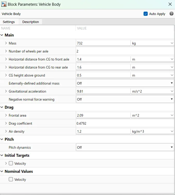
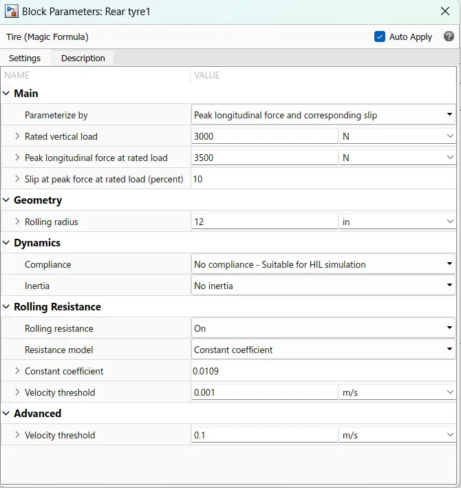
Fig 4 - Parameter blocks of Body & wheels
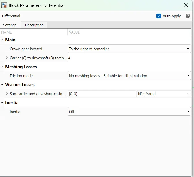
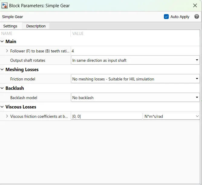
Fig 5 - Parameter blocks of Differential & Simple Gear
2] Drive Cycle or input signals :-
To run any automobile a reference input should be given which is nothing but a throttle so in this case the drive cycle is serves as a actual reference speed or drive pattern. In this project we shall use two different sources to run the e-rickshaw as the project aim suggest. These inputs will be provided in below forms,
- Drive cycle source - Here three random cycles will be used to track the rickshaw's performance
- Signal builder block - To generate a constant input of 45kmph
Actual block arrangemnet is shon in below fig 6 with all its configured parameters provided in fig 7,
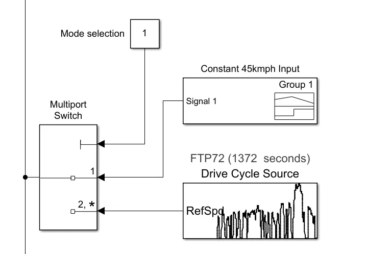
Fig 6 - Arrangement to select the modes between Signal Builder and Drive Cycle Block
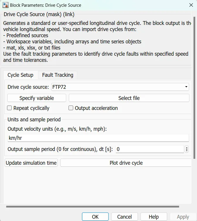
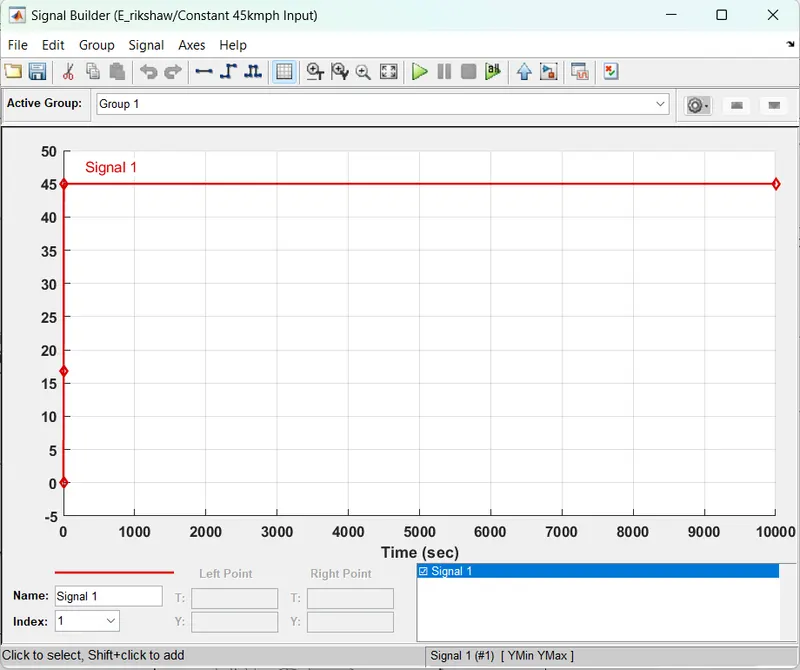
Fig 7 - Parameter blocks of Drive Cycle Source & Signal Builder
The above fig 6 shows the actual arrangement to select the mode of operation for this e-rickshaw like whether we want to drove it against drive cycle or constant speed depends on the requirements.
3] Longitudinal Driver :-
To drive any vehicle a manual instructor should be available to control and handle it so to do the same task a Longitudinal Driver block from powertrain blockset library is chosen. the actual block diagram and parameters of this driver is shown in below fig 8. Here no eleivation of gradeability is considered so considered 0 value as input to that port.
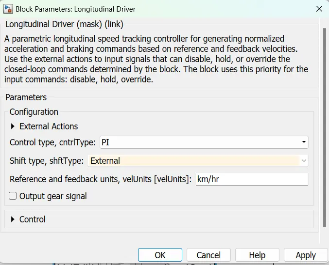
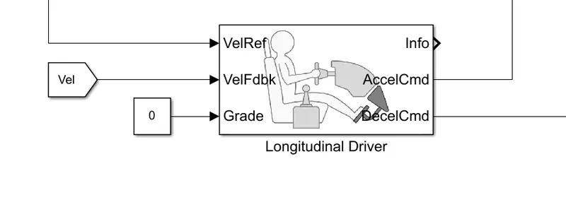
Fig 8 - Parameter blocks & Actual Block of Longitudinal Driver
4] H-Bridge Power Converter :-
Whenever we talk about electric powertrain it consist of three major components like motor, battery, power converter all these components plays an important role in vehicle propulsion. So in our model we have chosen H-Bridge Converter which is used to obtain a reuqired voltage from battery and supply it to motor. In our case this is a typical boost converter which is a four quadrant chopper. This chopper is cosist of four internal semiconductor switches ( like MOSFET) which works in motor as well as re-generator mode.
In this project this H bridge is connected with attachment of controlled PWM voltage source as shown in fig 9. the function of this block is to provide the PWM pulses to this converter for its operation depending on the input from this PWM voltage this bridge generates the required output volatge to motor. It has four input signals and three output signals in which two terminals that are positive and negative for motor and H port is thermal port to mesuare and observe the thermal characteristics of this controller. All the values of these block's parameter is provided in below fig 9 and all these parameters are retained from the actual values of BAJAJ RE and assumptions made.
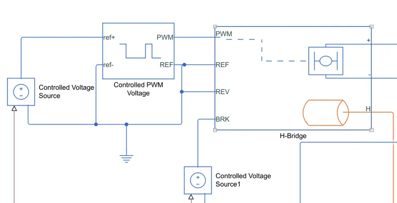
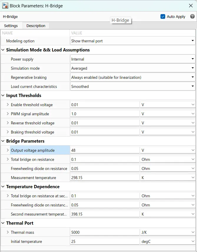
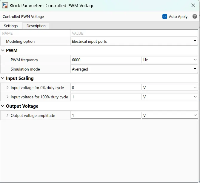
Fig 9 - Parameter blocks of H bridge & Controlled PWM Voltage
In this project model tempreture of converter is taken into accound and need to observe the actual tempreture of this block when it runs the vehicle so the output of its thermal port 'H' is provided to teampreture sensor whos arrangement is discuss further. So importanat factor while accounting the thermals of any device is its Thermal Mass , also known as heat capacity, is the ability of an object to absorb and store energy as heat. The higher the thermal mass of an object the more energy is required to change its temperature. In our model we have consider high thermal mass in order to get the required results. Also initial tempreture is set to 25 degC as defualt ambient tempreture. All these values can be seen in above figures.
5] DC Motor :- As the aim suggest a typicall burshed DC motor is used for the modeling of E- Rickshaw model so a DC Motor block from simscape library is chosen and used in the model itself as shown in given fig 10. The ratting is given to this motor for two different conditions which by considering actual BAJAJ RE motor power and battery back power and another with higher ratting of power , voltage and battery capacity to track the drive cycle inputs. The DC motor arrangement is shown below with parameters cosidered as per the details specified before.
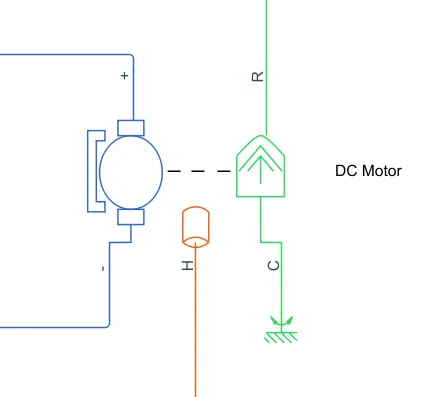
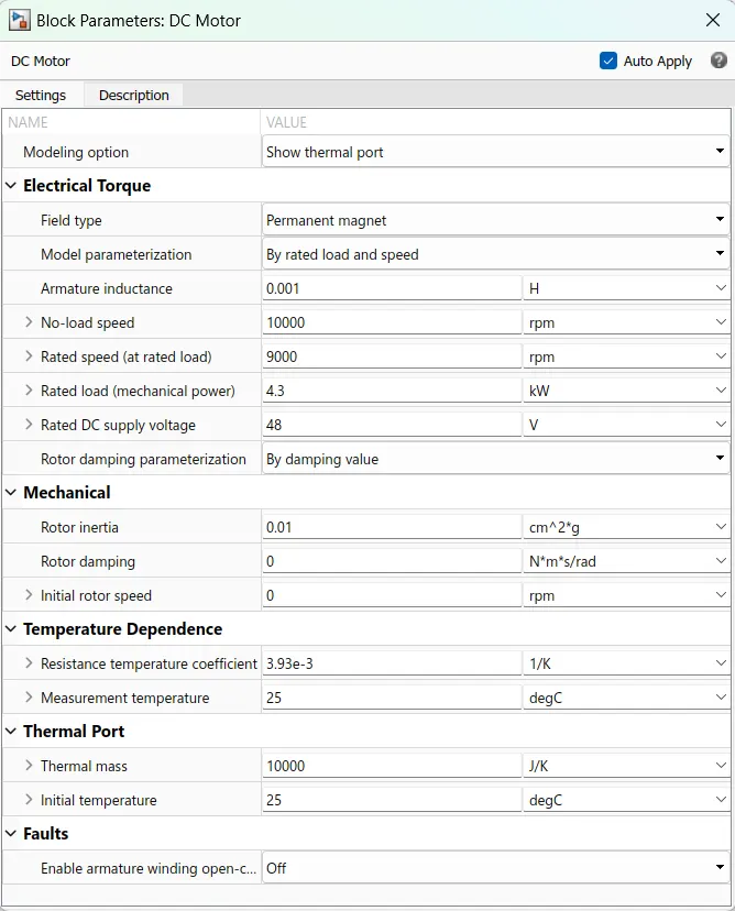
Fig 10 - Parameter blocks of DC Motor
In above both schemetics a thermal port and thermal mass term is specified which means the tempreture parameter of DC motor is taken into consideration while simlation. So the termal mass value is selected slightly high to achieve the desired results as required. All values are considered as per actual paramater of e-rickshaw and the tempreture port is connected to external tempreture sensor to measure it and observe its behaviour.
6] Li-ion Battery Pack :-
Battery pack is one of the major part in EV drivetrain or powertrain because it replaces the actual fuel and might be considered as fuel for eletric vehicles specially for their motors and other pheripherals. In our model we have calculated the battery pack size based on the power of BAJAJ RE Electric Rickshaw and it is found to be Ah = 165 amps, battery capacity = 8 kWh for 120 kms of range & max. speed of 45 kmph with 48v voltage as specified from BAJAJ.
So the battery block from simscape library is chosen which has inbuilt battery SOC % calculations and have many types of different battery packs like Li-ion, NiCd, Lead-Acid etc. So for our model we have chosen Li-ion battery pack as it is more efficient than other batteries. The parameter assigned to this pack is provided in below fig 11.
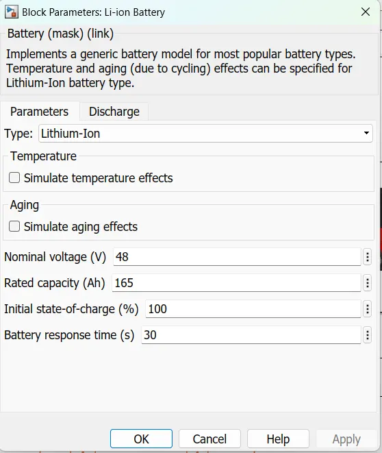
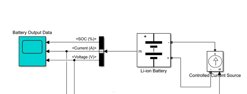
Fig 11 - Parameter block & Connection of Battery pack
7] Other Miscleneous :-
In this section we will discuss in detail about the other topology which are used in model to find out the enegry consumed while running the model for each mode & cases and Temperatures of motor and controllers as the aim suggests. So please check below details of these topologies used,
a. Energy Consuption - To calculate the energy consuption the below arrangement is used which is shown in fig 12. In this case the battery current and voltage is taken and then multiplied to find out the actual power consumed then integrated the same value to find out energy. The recieved values is devided by 1/3600 secs which is seconds in 1 hr to get energy in watt-hour and it is devided by 1000 to get the value of energy converted into kWh , as shown below.
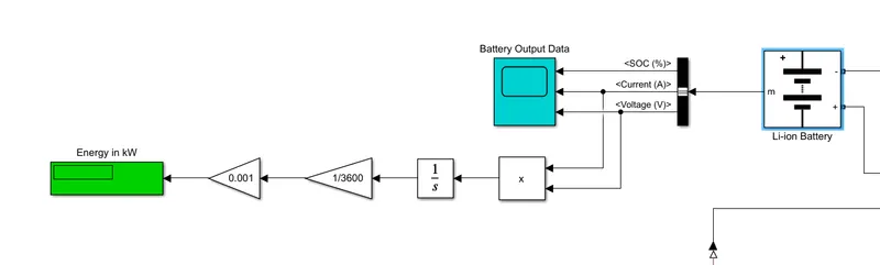
Fig 12 - Energy Consuption Calculation Topology
b. Temperature Rise of Motor and Converter - To measure the actual values of motor and converter a typical temperature sensors from simscape is used as shown and these are connected to both the block through its ports. This sensor have three ports A is positive terminal , B is negative terminal & T is output values of this block. The actual connection and arrangement is shown in below fig 13.
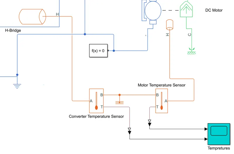
Fig 12 - Temperature Measurement topology
3. Results :-
This section is regarding the performance and the tests performed on this model to check its vaibility. This model is simulated and anaylize in two parts or cases to understand its practical performance as mentioned below -
- Using Actual technical parameters of "BAJAJ RE Electric" and specifications.
- Using the different values to match the driver cycles input to achieve the objective of aim.
Actual Simulink Model of BAJAJ RE Electric :-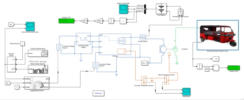
Fig 13 - Simulink Model of BAJAJ RE Electric Rickshaw
Case A - Using Actual technical parameters of "BAJAJ RE Electric" and specifications.
1] Results FOR FTP 75 Drive Cycle -
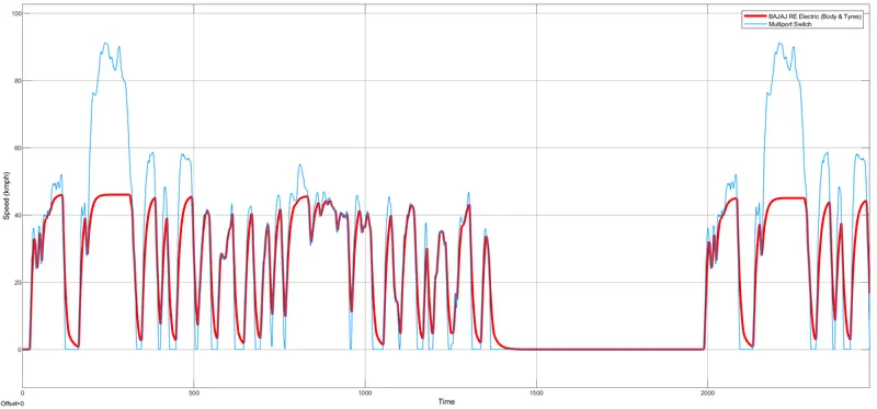
Fig 14 - Scope output of Actual Vehicle Performance
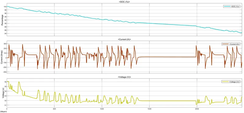
Fig 15 - Scope output of Battery Pack with SOC , voltage & current
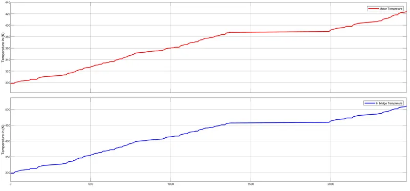
Fig 16 - Temperatures of Motor & H-Bridge Controller
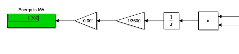
Fig 17 - Energy consumed by vehicle
2] Results FOR SC 03 Drive Cycle -
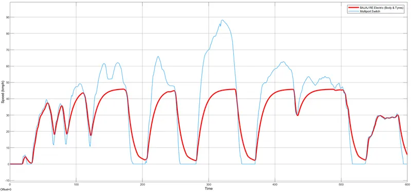
Fig 18 - Scope output of Actual Vehicle Performance
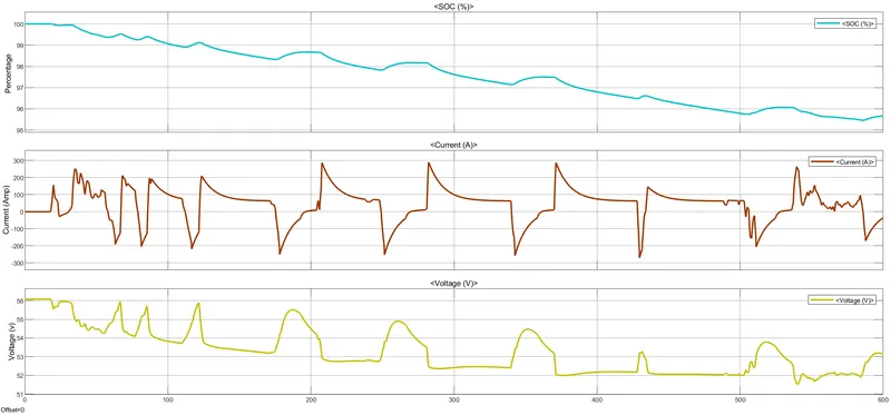
Fig 19 - Scope output of Battery Pack with SOC , voltage & current
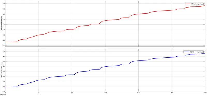
Fig 20 - Temperatures of Motor & H-Bridge Controller
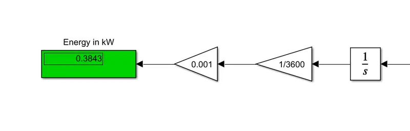
Fig 21 - Energy consumed by vehicle
3] Results FOR UDDS Drive Cycle -
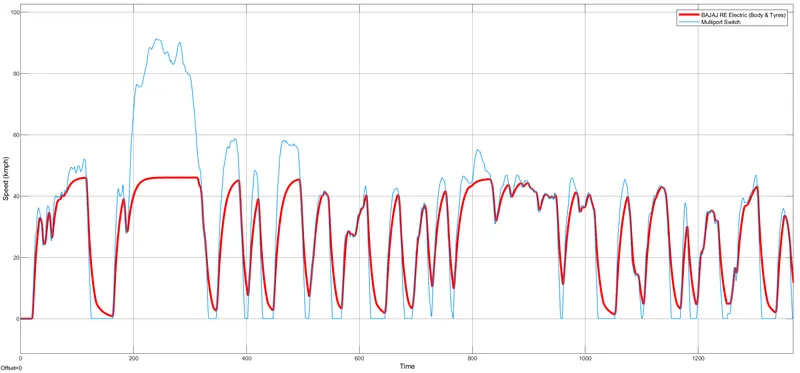
Fig 22 - Scope output of Actual Vehicle Performance
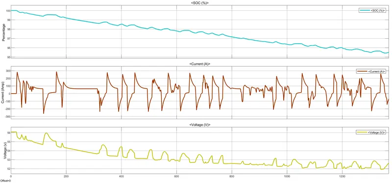
Fig 23 - Scope output of Battery Pack with SOC , voltage & current
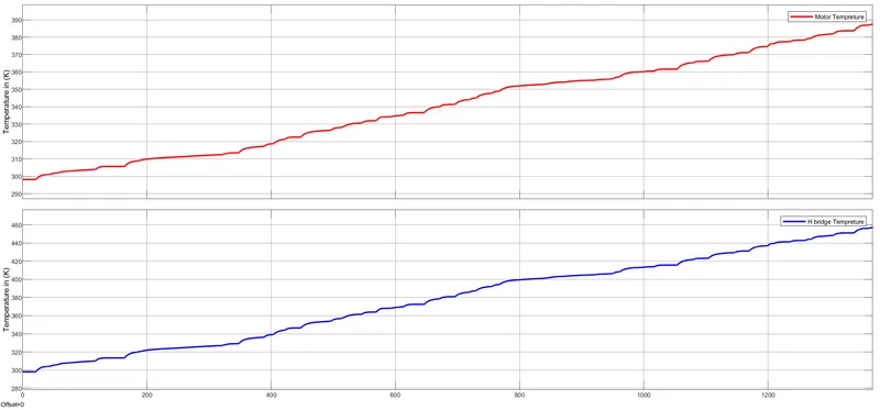
Fig 24 - Temperatures of Motor & H-Bridge Controller
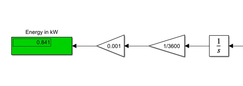
Fig 25 - Energy consumed by vehicle
4] Results FOR 100 km constant speed driving at 45 kmph -
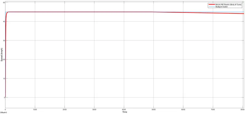
Fig 26 - Scope output of Actual Vehicle Performance
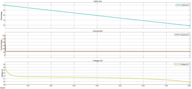
Fig 27 - Scope output of Battery Pack with SOC , voltage & current
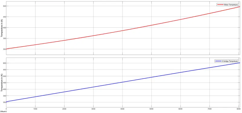
Fig 28 - Temperatures of Motor & H-Bridge Controller

Fig 29 - Energy consumed by vehicle for 100kms distance
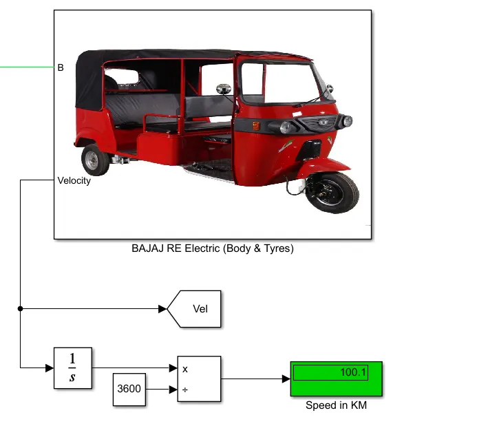
Fig 30 - Distance Display block for 100 kms
Case B - Using the different values to match or track the driver cycles input to achieve the objective of aim
Here we have increased the value of motor power, battery capcity and voltage to track the actual drive cycle as earlier voltage was low ( 48v) so motor would not be able to track the speed. So new updated values are
Battery Capacity = 150 Ah
Motor power = 90kW
Motor Rated speed = 18000 RPM
Voltage = 280 v
Tracking results for FTP 75 Drive Cycle -
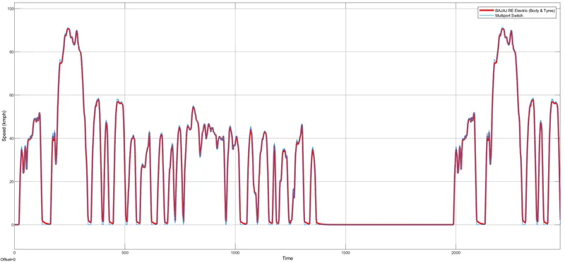
Fig 31 - Actual tracking of input drive cycle FTP 75
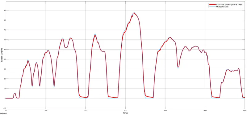
Fig 32 - Actual tracking of input drive cycle SC 06
From above fig 31 & fig 32, it can be seen that the rickshaw is following the input reference drive cycles after the we varied the parameters which as discussed and stated above.
4. Conclusion -
We are going to draw our conclusion based on two condition which were discussed in result section, So those cases for conclusion are -
a. When actual technical parameters of "BAJAJ RE Electric" and specifications used.
- While using the original parameters of BAJAJ RE rickshaw was able to perform same as its specs like it was tracking the input signal till it reaches to 45 kmph but as soon as reference speed goes above it the rickshaw not tracking the drive cycle. This can be understood from case 1 of results section.
- The main reason behind not tracking those input drive cycles is beacuse e-rickshaw's are not built for high speed. The lower capacity motors generally used and the voltage ratting is another important factor due to which motor not able to track the drive cycles.
- But, for constant 45 kmph speed the model successfully track the input signal and completed distance of 100 kms as shown in figures 26 to fig 30.
- In this case, we can conclude that the drive cycles we used was not indian ,specially not designed for rickshaw of lower speed, so thats why this model with original parameter able to track till its specific actual values and didnt go beyond those values. Finally its successfully analyzed and verified that this model with original parameters performed well and make it to get the results near to actual BAJAJ RE Electric.
b. When parameters are varied to match or track the driver cycles.
- We have tried to play with the values of motor, battery pack & voltage levels just to observe the performance of this e-rikshaw model whether it is tracking input reference signals or not.
- When the voltage and other parameter increased then the e-rickshaw started tracking the reference drive cycles and performed well as required as shown in fig 31 & fig 32. From this scope output it is clearly understood that e-rickshaw is tracking drive cycles. These all drive cycles are designed for foreign traffic conditions but in india its way different. Like max. speed of these rickshaws around 40-50 kmph they cant push beyond that and thats how they were design.
- So in this case, we can conclude that to track to track the input drive cycle the capacity of motor , battery and their voltage level must be chosen high in order to track the high speed and braking performance according to drive cycles.
Hence final conclusion can be draw in straight and simple way that the built model is performing well in required order so this model resembles the actual Electric Rickshaw model.
References -
- Colin Cochrane, Tariq Muneer, & Bashabi Fraser. (2019). Design of an Electrically Powered Rickshaw, for Use in India. School of Engineering and Built Environment, Edinburgh Napier University, Edinburgh EH10 5DT, UK.
- Dr.D.M. Holey, Miss. Divya Pakhare, Miss. Radhika Shahade, & Miss. Ritu Bangade. (2022). Design of E-Rickshaw using MATLAB. 2022 JETIR May 2022, Volume 9, Issue 5.
- https://evfunda.com/bajaj-re-electric-auto-rickshaw/
- https://www.wheelsatev.com/2020/09/battery-pack-capacity-calculation-for.html#:~:text=Using%20equation%20V*AH%2F1000,get%20AH%20is%2016.6%20Amp
Note : Enclosed all the files related to model and project.