Project-1: Powertrain for aircraft in runways
PROJECT 1
Objective : - Develop the model for Powertrain for aircraft in runways.
Part A :
1. List of total 20 different weights of various types of aircrafts available -
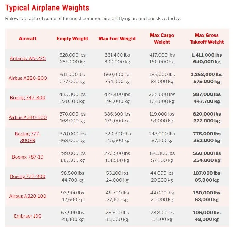
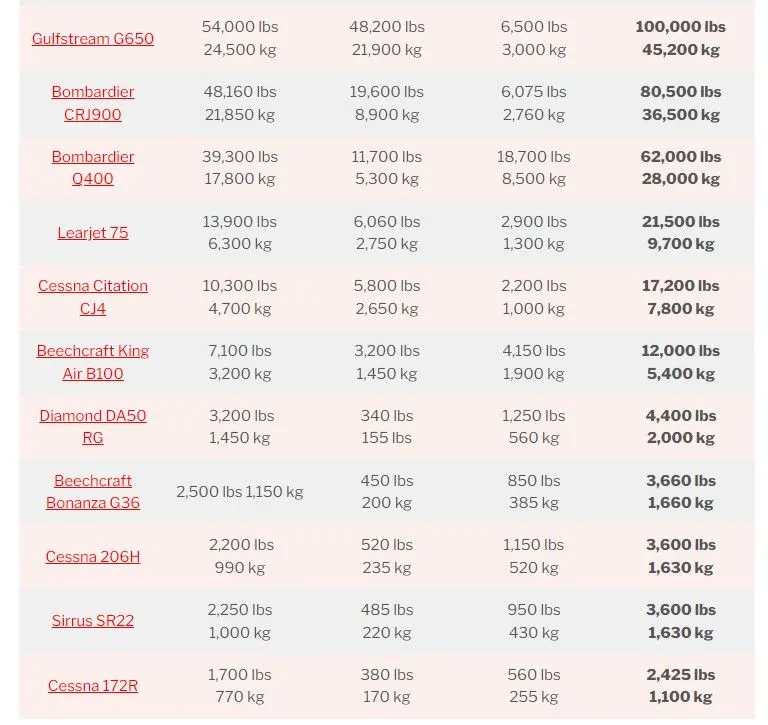
2. Difference between Ground speed and Air speed -
Air Speed, a true airspeed is simply the speed at which an aircraft is moving relative to the air it is flying in. As such, it’s also the speed at which the air is flowing around the aircraft’s wings.
Ground speed, on the other hand, is the aircraft’s speed relative to the ground. One thing that should be noted here is that it’s its horizontal rather than vertical speed – an aircraft climbing completely vertically would have a ground speed of zero.
In other words, while airspeed is what determines whether there is enough airflow around an aircraft to make it fly, ground speed is what determines how fast an aircraft will get to its destination.
The relationship between airspeed and ground speed is fairly simple. Ground speed is simply the sum of airspeed and wind speed. If the aircraft is flying in the same direction as the wind is blowing, the aircraft experiences tailwind, and its ground speed is higher than its airspeed. On the other hand, if the wind is blowing against the direction the aircraft is traveling in, the aircraft experiences headwind, and its ground speed is lower than its airspeed.
So,
Ground Speed = Airspeed + Windspeed
A. if aircraft is flying in same direction of air then it experiance the Tailwind,
Ground Speed = Airspeed + Windspeed
B. if aircraft is flying in opposite direction of air then it experiance the Headwind,
Ground Speed = Airspeed - Windspeed
3. Why is it not recommended to use aircraft engine power to move it on the ground at Airport?
The Phenomenon of moving the aircraft on the ground level using its engine is possible infact their engines generally working maximimum time of its journey. The movement can be done by using reverse & forward Thrust of aircrafts engine but it is not advisable in practice,When a plane departs an airport, its first movement will be to push back from the gate. To do so, an aircraft will generally use a small but powerful 'tug' truck to reverse it away from the terminal building.
What is actually Thurst or Reverse Thrust -
During landing, an aircraft's engines can be set to reverse thrust mode. This helps to slow it down by acting against the aircraft's forward travel. To explain the process on a basic level, air is 'sucked' into the engines, but then instead of moving to the rear, it is ejected through new openings in the aircraft's side that 'reverse' the movement.
There are several reasons behind not recommend to use aircraft engine power to move it on the ground at Airport. As such, many aircraft today are banned from doing so. While it is technically possible for aircraft to do so, there are many things that can go wrong with this practice. For example, the air blast around the aircraft can stir debris that may cause damage. This could affect the gate itself, other ground vehicles and aircraft, or anyone standing near the plane. The ground crew would need to clear the area before the engines are activated, and this might not save any time compared to using a tug. There is also the consideration of items being 'sucked' into the engine themselves. As the engine spins with increasing power, it creates a vortex. This could pull items such as tools into the expensive engines.
The power back operation also uses a lot of fuel and is very loud. Today, noise pollution is becoming an increasingly controversial factor of airport operations. Therefore, it is understandable that stakeholders wish to avoid this practice. Finally, pilots in the aircraft can't see behind them, as aircraft do not have rearview mirrors like cars. As such, they would need a spotter on the ground anyway. This would negate the point of doing a movement without any help.
Simply put, it is too risky for the airport, the ground crew, and the aircraft to deploy reverse thrust that close to the terminal building. The upside is a few minutes and dollars saved, but the downside could be millions in damage and a grounded aircraft. As such, the small but mighty workhorses of an airport's tug fleet will continue to push aircraft back for the time being.
5. Learn about take off power, tyre design, rolling resistance, tyre pressure, brake forces when landing ?
Take off Power :
On take-off, in order to position the aircraft to a safe height away from terrain and obstacles (i.e. a flight path of maximum height and minimum ground distance desired), the engine thrust is set to a high ‘take-off power’ setting (although this is not necessarily full power) and the aircraft attitude is pitched up to maintain a specific speed (usually in the region of V2 + 15kts). Once the ‘safe height’ is reached the engine thrust can therefore be reduced to a more appropriate (i.e. efficient) setting and the aircraft flight path can be changed to a more appropriate (i.e. efficient) flight path. There are two possible conditions that either aircraft use full thrust power to take off in case of low weight aircrafts or use half of the thrust power in case of high weight.
A derated thrust takeoff is a takeoff that is accomplished utilising less thrust than the engines are capable of producing (thrust rating) under the existing conditions of temperature and pressure altitude.
Benefits of derated takeoffs -
- Engine reliability
- Less maintainance
- Improved operating cost
- Takeoff weight flexibility for specific runways
Takeoff operations conducted at thrust (power) settings less than the maximum takeoff thrust (power) available may provide substantial benefits in terms of engine reliability, maintenance, and operating costs.
Tyre Design :
When it comes to safety, tyres are one of the most important components of aircraft. They help to absorb the shock of landing and provide cushioning. It also provides the necessary traction for braking and stopping of an aircraft. An aircraft tyre is designed to withstand extremely heavy loads while landing, take off, taxing, and parking. The number of wheels required for aircraft increases with the weight of the aircraft, as the weight of the aeroplane needs to be distributed more evenly.
Design & Construction -
Carcass plies are used to form the tire. They are sometimes called casing plies. An aircraft tyre is constructed for the purpose it serves.
- They support the weight of an aircraft while it is on the ground.
- It also provides the necessary traction for braking and stopping of an aeroplane.
- Tyre also helps to absorb the shock of landing and provide cushioning the roughness of takeoff, roll-out, and taxi operations.
Unlike an automobile or truck tyre, it does not have to carry a load for a long period of continuous operation. However, an aircraft tyre absorbs the high impact loads of landing, and also it’s operating at high speeds for a short time when required.
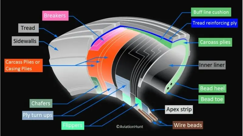
Some technical terms related to Tyres ,
Retreading – Retreading is methods of restoring a worn tyre by renewing the tread area or by renewing the tread area plus one or both sidewalls. Repairs are included in the tyre retreading process.
Load Rating – Load rating is the maximum permissible load at a specified inflation pressure.
Ply Rating – Ply Rating is used to identify the maximum recommended load rating and inflation pressure for a specified tyre. It is an index of tyre strength.
Speed Rating – The speed rating is the maximum takeoff speed to which the tyre has been tested.
Skid Depth – Skid depth is the distance between the tread surface and the deepest groove as measured in the mould.
Aircraft tyres must have an approved speed and load rating and have sufficient clearance when retracted through landing gear to allow for tyre growth. Tyre growth is the increase in the size of the tyre due to centrifugal forces at high speed.
Tubeless tyres are more advantageous over tube-type. There is no longer the use of tube-type tyre in recent aviation. Nowadays all airliners are using tubeless tyres. Tubeless that are meant to be used without a tube has the word TUBELESS on the sidewall of the tyre.Almost all airliners are using Radial tyre. Bias is an older design, and it’s mainly used for road vehicles. Radial tyres have the word RADIAL on the sidewall. Radial tires are more expensive than bias-ply tyres. Radial tires are in demand because of their lower life cycle cost and long term value.
Rolling Resistance -
Tire rolling resistance is the energy that your vehicle needs to send to your tires to maintain movement at a consistent speed over a surface. In other words, it is the effort required to keep a tire rolling. The main contributor to rolling resistance is the process known as hysteresis. Hysteresis is essentially the energy loss that occurs as a tire rolls through its footprint. The energy loss must be overcome by the vehicle’s engine, which results in wasted fuel. Rolling resistance, in simpler language, is just the energy that is needed to keep your tyres rolling at a steady and straight pace.
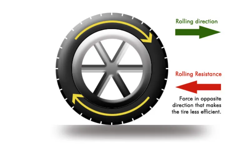
Rolling resistance is going to happen whenever a tire makes contact with a road surface. However, although it can’t be avoided, it can be minimized. Since tire rolling resistance is caused by hysteresis, tires can be engineered with specially formulated tread compounds that are more resistant to heat generation and constructed to minimize tire deflection for less energy loss. These are known as low rolling resistance tires.
Tyre Pressure of Aircrafts -
No other tire has to deal with such high load and extreme speed as an airplane tire. So they need a bit more care than the tires on your car or motorcycle. Think of the role of the tire as holding the air at a pressure that is able to support the load of the airplane. (Nitrogen is normally used in commercial operations instead of air.)
Maximum Pressure in aircraft tyre is 200 PSI.
Brake Forces during Landing -
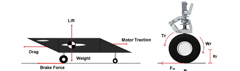
The main part of the aircraft kinectics energy is dissipated by the brake system when landing. The brake force is
derived from the counter torque to the wheels movement, which is generated from the brake system actuators. The Fig.
3 shows the forces acting on the aircraft and the wheels during braking time.
From this above fig we can state that below forces acting on Aircraft while landing -
- Weight
- Aerodynamic Drag
- Lift
- Thrust
- Rolling Resistance
- Braking force (which introduce the counter torque)
Part B :
6. A. With necessary assumptions, calculate the force and power required to push / pull an aircraft by a towing vehicle.
In this case we would consider to find out the forces acting on Aircraft and Tug ( towing van) initially and then calculate the power for the same. So now going further with aircraft calculations first but before that we shall tally how many forces are acting on both of these,
- Rolling Resistance Force
- Aerodynamic Drag Force
- Acceleration Force
For Airfcraft
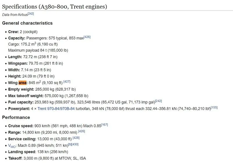
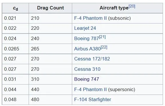
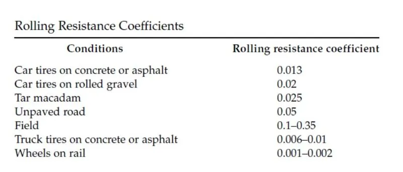
Let us consider the Airbus A 380 Aircraft and its respective parameters. We are taking some parameters as it is and some other are assumed as mentioned below -
Max. Takeoff weight (mass) = 575000 Kg
Air Drag coefficient Cd = 0.0265
Rolling Resistance Constant Urr = 0.01
Frontal Area = 24.09*7.14 = 172 `m^2`
Speed of Aircraft while pushback or towing v= 15 Kmph = 4.17 m/s
Acceleration time t = 10 sec
1) Rolling Resistance Force
F_r = mu_r *m * g
where,
`F_r`= Rolling resistance force
`mu_r`= Rolling resistance constant
m = mass of aircraft
g = acceleration due to gravity
`therefore F_r = 0.01*575000*9.8`
`F_r` = 56350 N
2) Aerodynamic Drag Force
`F_d = 1/2*rho*A*Cd*v^2`
where,
`rho` = air density in `(kg)/m^3`
A = frontal area in `m^2`
Cd = Air drag coefficient
v= velocity in m/s
`therefore F_d= 1/2*1.25*172*0.0265*4.17^2`
`F_d = 49.54 N`
3) Acceleration Force
`F_a =m*a`
`F_a = m*((vf-vi)/t)`
where,
m= mass in kg
a= acceleration in `m/s^2`
vf= final velocity in m/s
vi= initial velocity in m/s
`therefore F_a =575000*((4.17-0)/10)`
`F_a = 239775 N`
For Tug (towing van)
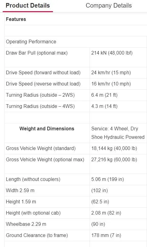
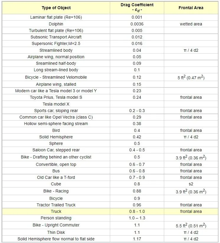
Here considering the Tug model name B600 from Asian Impex Logyistics Inc. we are retaing all its parameter and assuming some required parameters to find out the force and power respectively.
Max. gross weight (mass) = 27216 Kg
Speed v = 16 kmph = 4.44 m/s
Frontal Area A= 1.59x2.59 = 4.12 `m^2`
Rolling resistnace constant = 0.01
Air Drag Coefficient = 0.8
Time t = 10 sec
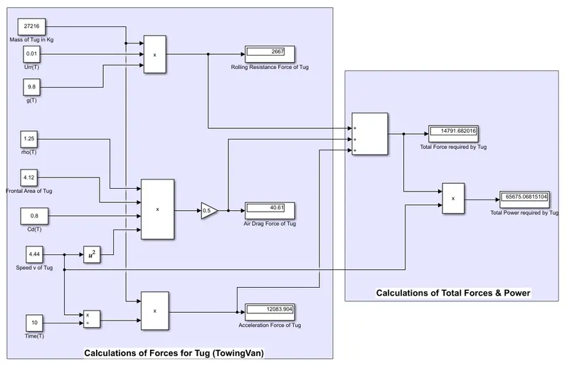
1) Rolling Resistance Force
F_r = mu_r *m * g
`therefore F_r = 0.01*27216*9.8`
`F_r` = 2267 N
2) Aerodynamic Drag Force
`F_d = 1/2*rho*A*Cd*v^2`
`therefore F_d= 1/2*1.25*4.12*0.8*4.44^2`
`F_d = 40.61 N`
3) Acceleration Force
`F_a =m*a`
`F_a = m*((vf-vi)/t)`
`therefore F_a =27216*((4.44-0)/10)`
`F_a = 12083.904 N`
Now to calculate total forces required by tug to pull/push the aircraft is given below however as per mentioned specifications and assuption this Tug is capable to pull the total takeoff load of aircraft so,
Total Force =`F_r (Tug)+F_d (Tug)+F_a (Tug)`
`= 2267+40.61+12083.904`
`F_t = 14791.514 N`
The total force required to pull the aircraft is 143.92 kN combined of tug plus aircraft. So now to calculate the power we have to consider the velocity of tug as ultimately tug is going to pull/push the aircraft ,
As we know
Power = Force x Velocity
power = 14791.514 * 4.44
Power = 65675 Watts or 65.7 kW
From above power value it is considered that as the airbus aircraft is larger in size and has more weighing capacity so it would require more powerful tug ( towing van) to do their pushback at airports.
6. B. Develop the model for the calculated force and power using Simulink.
Using Above calculated parameters for Aircraft & Tug a Simulink model is developed to find our the all forces & power respectively. After simulating the model paramter values are found to be correct as per theorotical calculation made above.Schematic of Model in Simulink -
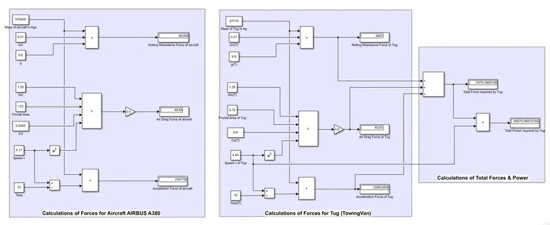
For AIRBUS A380
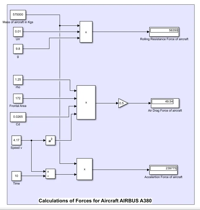
For Tug & power calculations
7. A. Design an electric powertrain with type of motor, it’s power rating, and energy requirement to fulfill aircraft towing application in Simulink. Estimate the duty cycle range to control the aircraft speed from zero to highest. Make all required assumptions. Prepare a table of assumed parameters. Draw a block diagram of powertrain
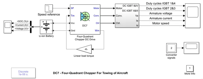
To model the powertrain for towng of aircraft some parameters are calculated first like energy , battery capacity , power & torque etc. DC7 block is used to model this drivetrain by cosidering some parameters as default for motor, controller & converter. Block diagram for powertrain is shown in below figure,
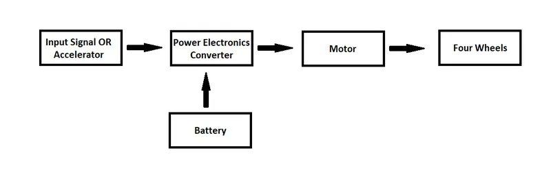
Fig : Block diagram powertrain for towing
Some important parameters are calculated as mentioned below -
Considering the working hours of towing vehicle is 1.5 Hr
`therefore Enrgy = power * hours`
= 65.7 x 1.5
Energy = 98.55 kWh
Battery capacity :
Assuming the losses in motor around 6-8% & in battery back ( charging and discharging ) is around 15-25% , so total losses % around 33% ( 8+25) and basis on this percentage the capacity can be calculated as-
Battery capacity = 98.55 + 98.55*30%
= 131.0715 kWh
Duty cycle = output power / input power
d = 98.55 / 131.0715
d = 0.75
since , Power = torque x speed
torque = power /speed
= 65.7 / 4.44
Torque = 14.8 Nm
Considering the voltage as 400v so
kWh = (Ah x V)/1000
Ah = ( kWh x1000)/V
= ( 131.0715 x 1000)/400
Ah = 327.67
According to above assumed & calculated parameters DC7 block is provided with battery insted of AC source with capacity of 327.67 Ah. Matlab model is simulated and observed the output as provided below ,
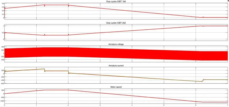
Output Scope -
Battery Scope -
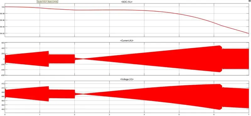
Explanation -
- All parameters are kept as it is of DC7 block only change made is that input power source that is battery. Li-Ion battery is used with the calculated capacity as mentioned above.
- Duty cycle is observed around 62.5 % from above scope outputs & above model is simulated for 7 seconds.
- Speed refernce was set from 500 rpm to -1000 rpm and its achieved successfuly.
- As working time of towing van was cosnidered 1.5 hrs and this model is simulated for 7 secs after 7 secs battery SOC dropped to 99.65% which is quiet practical.
Observations and conclusions : As total power is calculated to tow a aircraft is 65.7 kW so if we want to design the powertrain for tug or towing van then we must consider the motor ratting first like around 70 kW. Then process for converter and battery sizing. By considering the calculated power some motor study is done and check the available motor for this size and found as mentioned below -
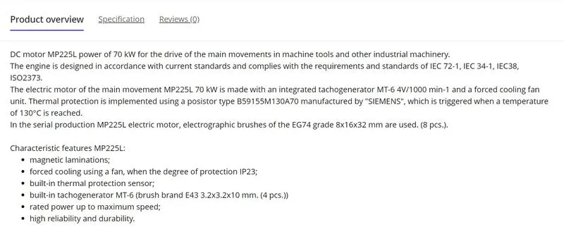
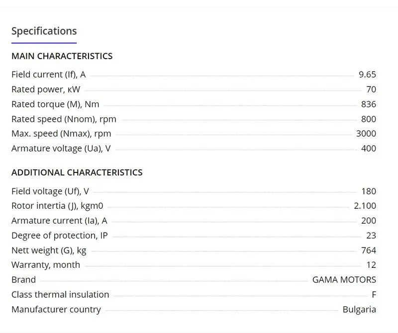
These all are practical values so it can be takne into cosnideration while developing the actual model.
Table of Assumptions :-
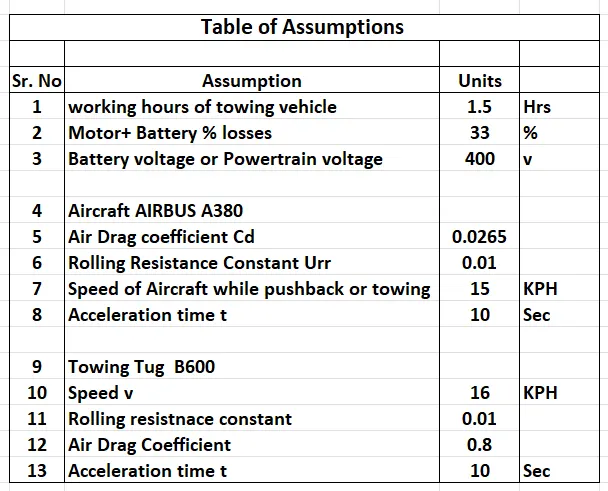
B. Also, Design the parameters in excel sheet.
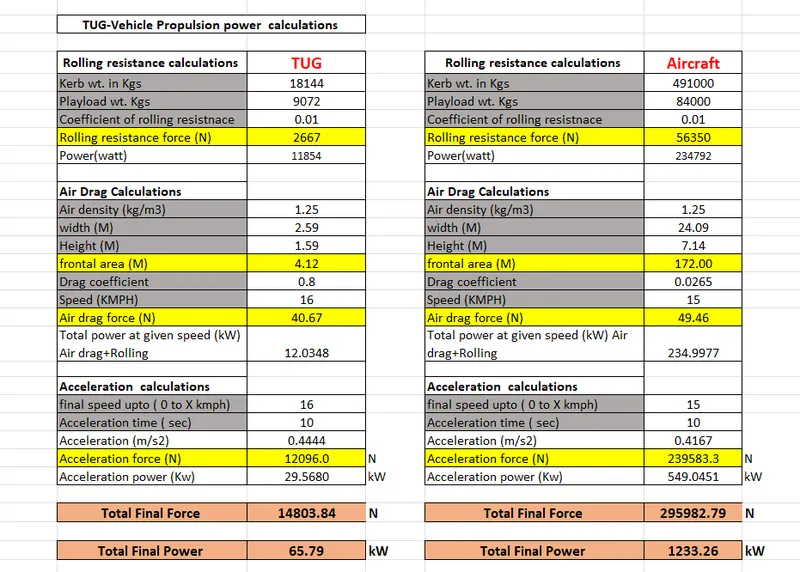
Note - Enclosed alll files related to above tasks
References :-
- https://pilotteacher.com/how-much-do-airplanes-weigh-with-20-examples/
- https://knaviation.net/airspeed-and-ground-speed/
- https://simpleflying.com/reverse-thrust-push-back/
- https://aviationlearnings.com/aircraft-towing-tractor-pushback-tractor-or-tug-the-machine-that-wrestles-with-the-giant-airplane/
- https://fl360aero.com/detail/aircraft-derated-take-off-a-general-understanding/238
- https://www.skybrary.aero/take-and-climb#:~:text=On%20take%2Doff%2C%20in%20order,attitude%20is%20pitched%20up%20to
- https://www.aviationhunt.com/aircraft-tyre-construction/#:~:text=Aircraft%20tyres%20may%20be%20Radial,expensive%20than%20bias%2Dply%20tyres.
- https://tyres.cardekho.com/news/things-to-know-rolling-resistance
- https://www.researchgate.net/publication/332201692_Aircraft_Braking_Dynamics_and_Brake_System_Modeling_for_Fault_Detection_and_Isolationhttps://www.engineeringtoolbox.com/plane-pull-force-people-d_2083.html