Week-6 Challenge: EV Drivetrain
Solutions :
Q1) Which types of power converter circuits are employed in electric and hybrid electric vehicle?
Solution : Different types of power converter circuits are,
a. DC - AC Power converters - DC to AC inverters are used for converting direct current (DC) into alternating current (AC). They are also known as DC to AC converters. DC/AC power inverters convert DC power from a battery or other power source (mostly 12 VDC) to standard household AC power (110VAC). Inverters use oscillator circuits to accomplish the inversion through a series of steps. The DC circuit flows down one end of the circuit with an electromagnet. When the current hit a magnet, the magnet activated and the current flow would change to the other side of the circuit cutting power from the electromagnet.
Nominal DC input values for DC to AC inverters can be 12 VDC, 24 VDC, 48 VDC, 110 VDC, 125 VDC, an 250 VDC.
b. AC-DC Power Converters - AC-DC converters are electrical circuits that transform alternating current (AC) input into direct current (DC) output. They are used in power electronic applications where the power input a 50 Hz or 60 Hz sine-wave AC voltage that requires power conversion for a DC output.
AC to DC converters use rectifiers to turn AC input into DC output, regulators to adjust the voltage level, and reservoir capacitors to smooth the pulsating DC. This video explains how AC is converted into DC.
Specs -
- Allowable AC input can be set (e.g., 115, 208, or 230 VAC only) or a range (e.g., 85-264 VAC).
- DC output is measured in watts (e.g., 3 to 1,000), volts (e.g., 3 to 380), and amps (positive or negative; 1.6 to 6,000).
- Operating temperature ranges (e.g., -20 to 70 C) are also given for AC DC converters.
c. DC- DC Power Converters - DC-to-DC converters are devices that temporarily store electrical energy for the purpose of converting direct current (DC) from one voltage level to another. In automotive applications, they are an essential intermediary between systems of different voltage levels throughout the vehicle.
Control circuitry played the role of DC-to-DC converter in the traditional 12V electrical architecture that dominated the automotive industry starting in the 1950s. Over the decades, new features and innovations increased the complexity of vehicle electrical/electronic architectures, including the introduction of cruise control in the 1950s, emission control features in the ’70s and electrical centers in the ’90s. DC-to-DC converters enabled this growth by stepping down power from the 12V battery to lower-voltage electrical systems such as the instrumentation panel, entertainment system, LED lighting and sensors (which can require as little as 3.3V). These low-voltage DC-to-DC converters are still an essential part of the control circuitry in all vehicles today — both in internal combustion engine vehicles and battery electric vehicles (BEVs).
d. AC- AC Power converters - AC to AC voltage conversion without changing the frequency can be performed in two ways. One is On-off control and another is AC phase control. On-off control process is also known as Integral cycle control.
In On-off control method the load power can be managed or controlled by connecting the source to the load for few numbers of complete cycles and then disconnecting it from source for another few numbers of cycles and then repeating the switching this cycling process again and again. This kind of conversion is suitable for system which has large time constant. It can be used in heating loads applications and average power of load can be varied from 0% to 10%
In AC Phase Control method thyristors are fired once after every cycle and then delayed from zero crossing. Only a part of voltage waveform appears across the load and provide control on voltage. The load current appears in pulses and zero crossing can be used to turn off the thyristors. This process is suitable for loads with short time constant; the output voltage can vary according to control over instant of firing.
References -
- https://www.globalspec.com/learnmore/electrical_electronic_components/power_supplies_conditioners/dc_to_ac_inverters#:~:text=DC%20to%20AC%20inverters%20are,household%20AC%20power%20(110VAC).
- https://www.aptiv.com/en/insights/article/what-is-a-dc-to-dc-converter#:~:text=DC%2Dto%2DDC%20converters%20are,voltage%20levels%20throughout%20the%20vehicle.
- https://www.yesmec.com/an-introduction-to-ac-to-ac-converters/
Q2) Solution :-
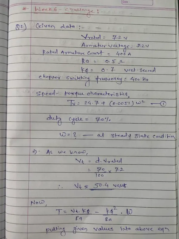
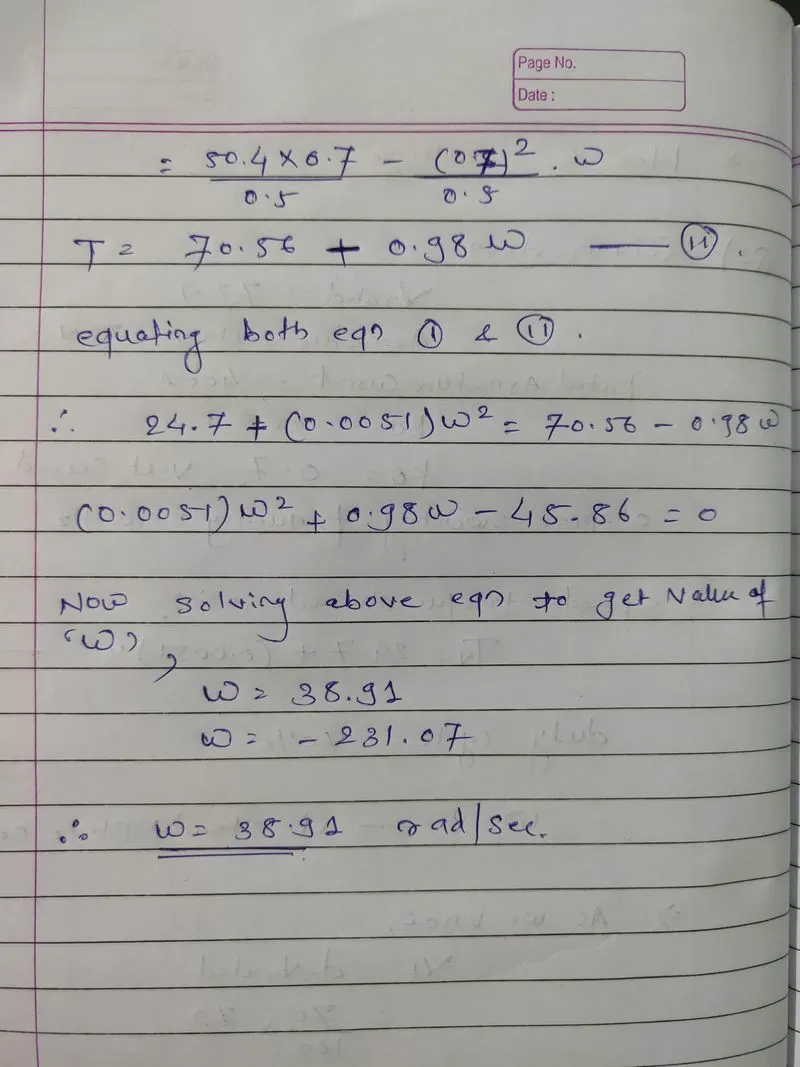
Q3) Developed a mathematical model for DC Motor for the given equation using Simulink :
All details are considered as per gievn parameters and sucessfully built a model for DC motor which provided below,
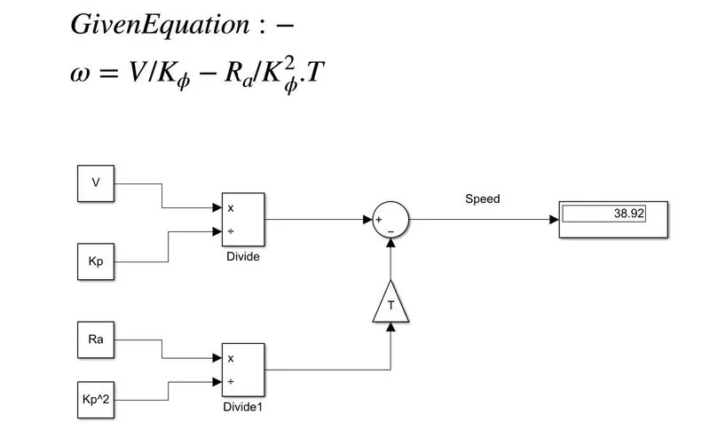
Input defined in M-Script file -
% Input values to Develop a mathematical model of a DC Motor
V= 50.4;    %Considered calculated terminal voltage in volts
Ra= 0.5;    %Armature resitance in ohms
Kp=0.7;     %Motor constant in Volt-sec
T =32.42  ; %output torque values in Nm taken from privious question.
Conclusion : In this mathematical model, we have implemented the basic mathematical logic and developed the model. Here in display the value of speed is reflecting, however if we cross check this value with question no 2 equations then the output found to be correct viz. speed = 38.92 rad/sec & Torque = 32.42 Nm. (Note - to cross check put the details in toqrue equation to find torque values and similarly put the same values in speed eqaution of above question then values of speed can be analyzed.)
Q4) Brief about author’s perspective -
Mr. Wally simply compared the advantages and applications of DC Drives (BLDC Motor) & induction motor and stated his openion on the same topic. Some brief points are provided below -
- One can not specify perfect universal size for application, every different appliation need different motor as each motor or engine has their own speciality. Same is applicable with batteries too.
- he explained the working principle of Brushless DC drives and induction motors. How the magnetic and electric fields gets produced and how motor results into the toruq or rotor movement.
- Both BLDC drive and induction motor have same stator design but rotors are different. One contains permanent magnet and other contains slotted conductors which generates the mangetic field.
- BLDC drive can not operates directly through inverter from DC source they need proper feedback control and phases should be synchronized in proper manner to generate the torque. However if it supplied through DC supply they will not generates the torque
- If induction motor connetced to DC power via inverter without feedback control it will be capable of running smoothly. Variable speed is also possible by adjusting the inverter frequency.
- Still induction motor have low torque capabilites as compared to DC machines and it has lower effiecient than DC. It needs to be operated around 85% power factor but DC machines can run on much higher power factor around unity too.
- He has stated his conclusion that DC machines will may dominate HEV & plugin HEV market in future and Induction motor in pure electric vehicles with high peroformance.
- In his perspective it might be possible that we witness DC machines and Inductor motor working live together in HEV & Pure EVs if these cars become more electrically intensive & powerful.