Project - 2 - Meshing on the suspension Assembly
OBJECTIVE:
To perform mesh on the given suspension model . To follow all the given quality and mesh parameters . Also use Appropriate connections to connect the component and perform symmetry.
GIVEN :
Note:
- Use Volume mesh for Tyre and Rim with below Quality criteria. (Use Tria Element)
- Use mid surface only when the thickness is uniform and less than 5 mm. (Use Mixed elements)
CAD MODEL:
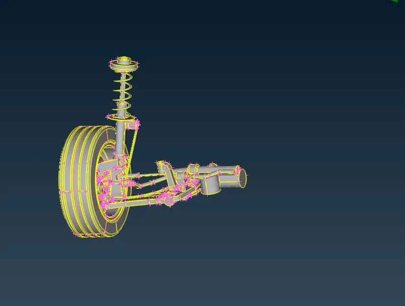
PROCEDURE:
- Firstly check the given model .Give cons resolution go to mesh module>lengths>permiter>1. Then go to check>geometry>visible>run . Do the the geometry check on the component individually to obtain proper geometry.
- secondly check the thickness of each component and store the value for future reference. As per the given question we have to perform solid mesh on parts having non uniform thickness and 2d mesh on uniform thickness part. measure>thickness>select cons/curves>store the value
- Before define the volume make sure parts undergo penetration check . check>penetration>intersections>run >ok
- The above two steps are common in all the procedure while performing mesh on components individually .
- From given, the tyre and rim component , we do geometry clean up and perfom the intial two steps .
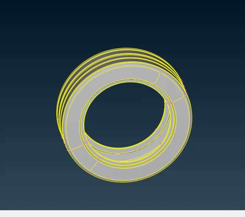 tyre
tyre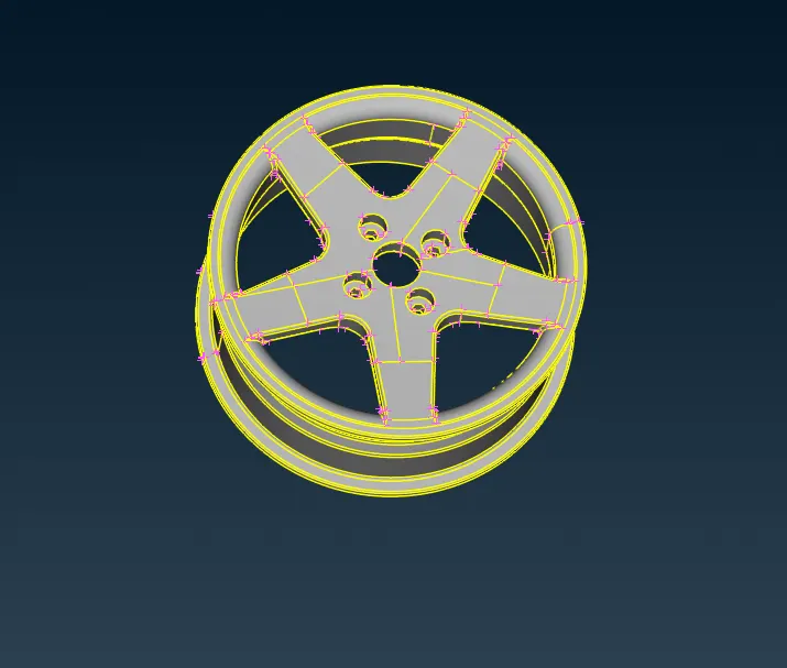
- Given mesh parameters and the quality parameters from the given question.
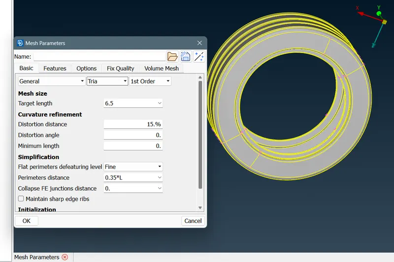
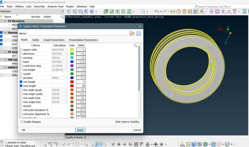
- We create 2d elements on the surface of the component and convert to solid elements by tetra volume. mesh module>mesh generations>spot/best>slect the surface>ok. After creating 2d elemnts on the component go for quality check before defining the volume.
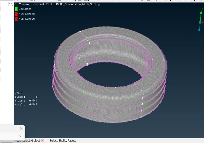 2d mesh tyre.
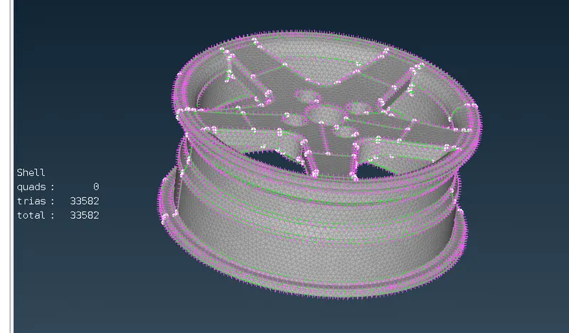 2d mesh rim .
- checking for penetration,
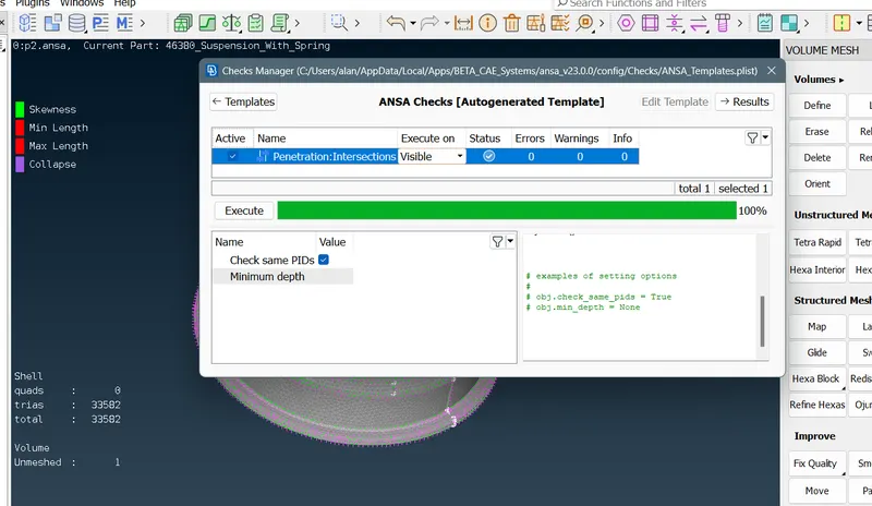
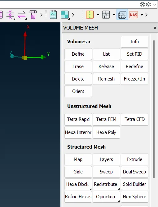
- For solid mesh volume mesh deck>define>visible. Next volume mesh deck>terta mesh>ok . Thus the solid mesh is opened. Check for any quality failure specially tet collapse as per the given criteria.
- we get,
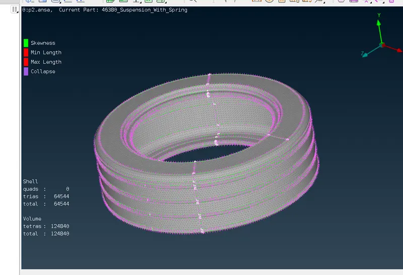 solid mesh on Tyre with quality criteria.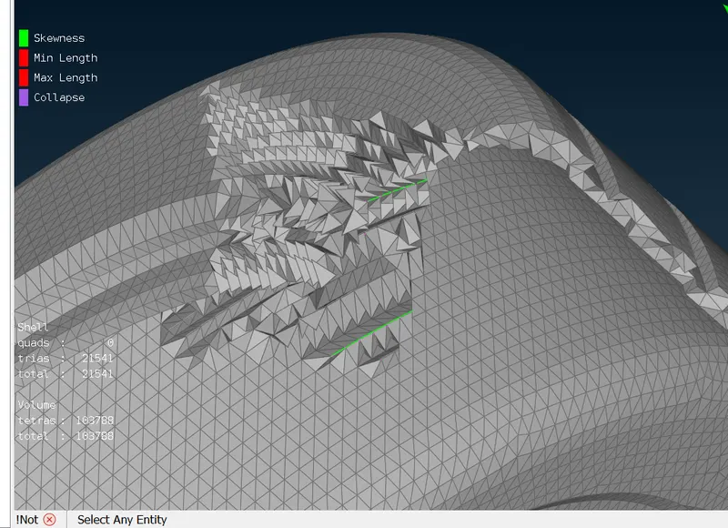
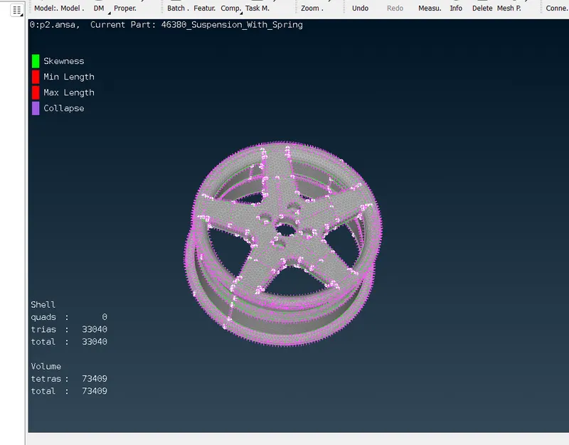 solid mesh on Rim and its quality criteria.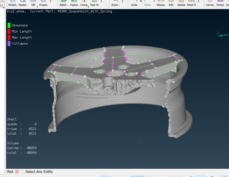
- thus we get ,
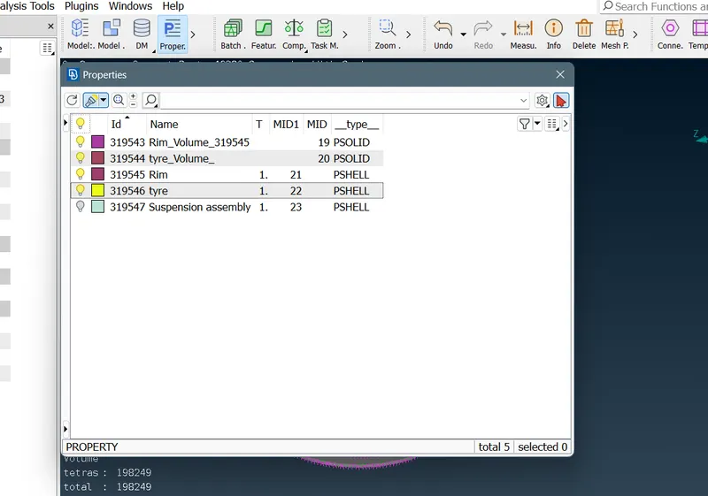
- Now we perfome the steps on different parts separately by creating new PID in property card .
- Performing mesh on the parts having non uniform thickness, doing geometry and topo clean up .
- Giving mesh parameter and quality parameter from the given question,
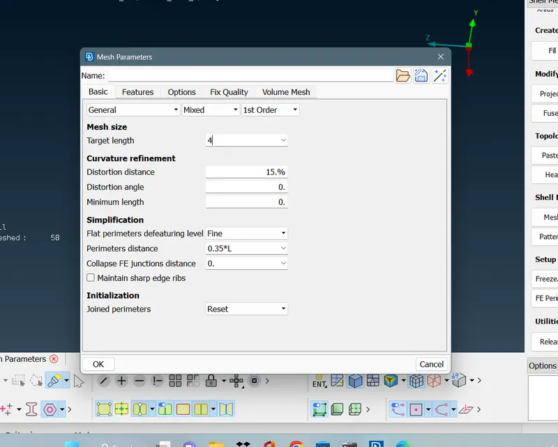
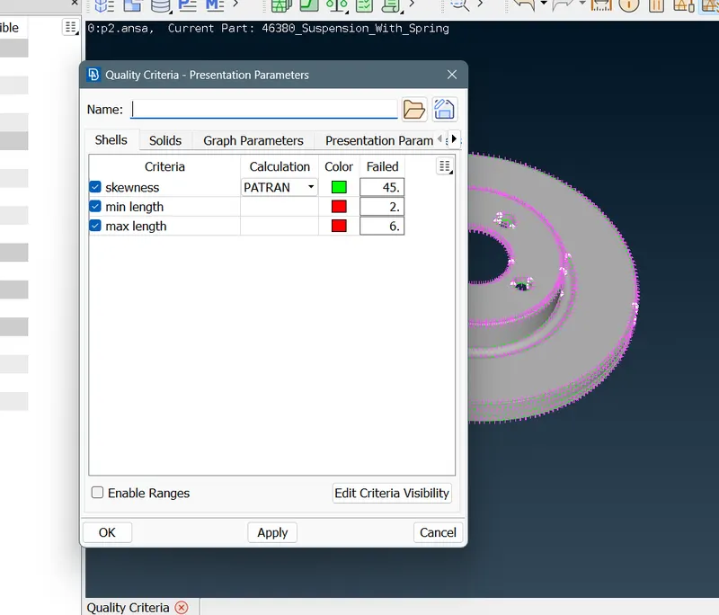
- Creating 2d mesh on those parts one by one respectively and going for solid mesh we get , similar to the above tyre and rim steps.Do check for penetration criteria.
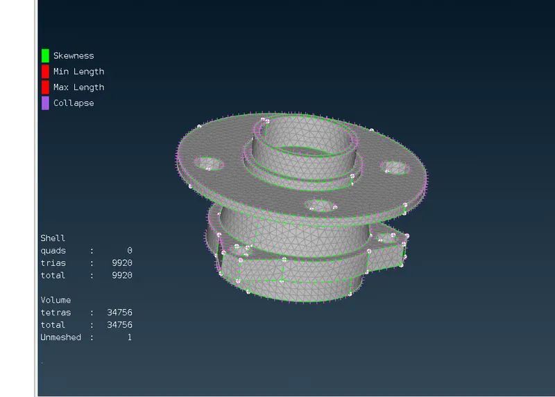
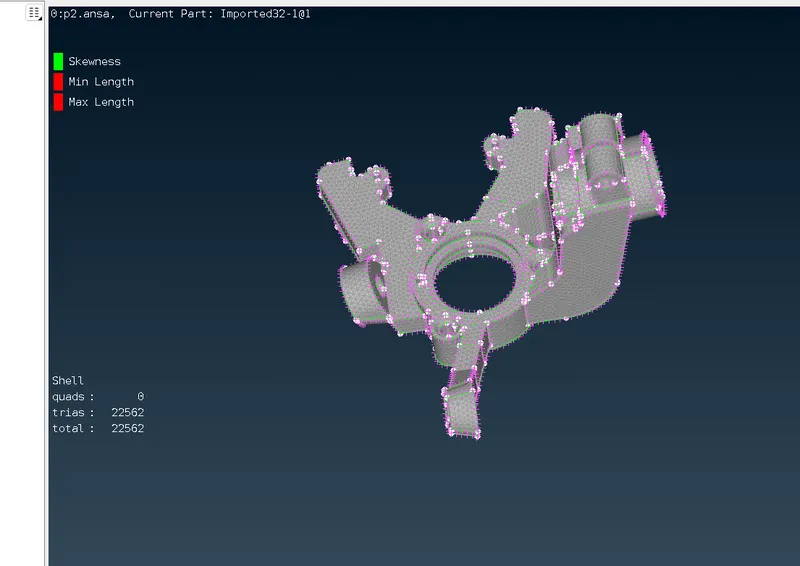
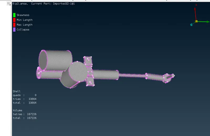
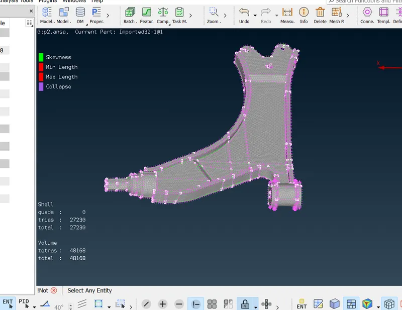
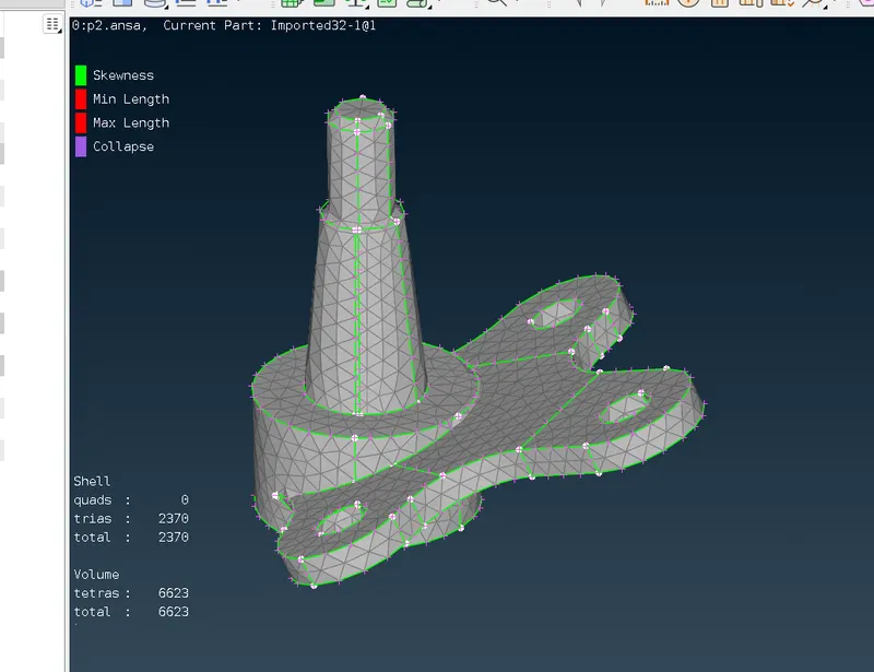
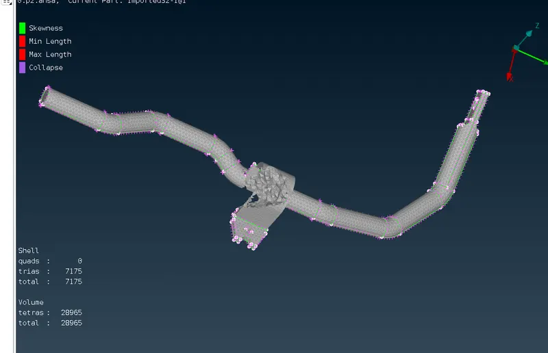
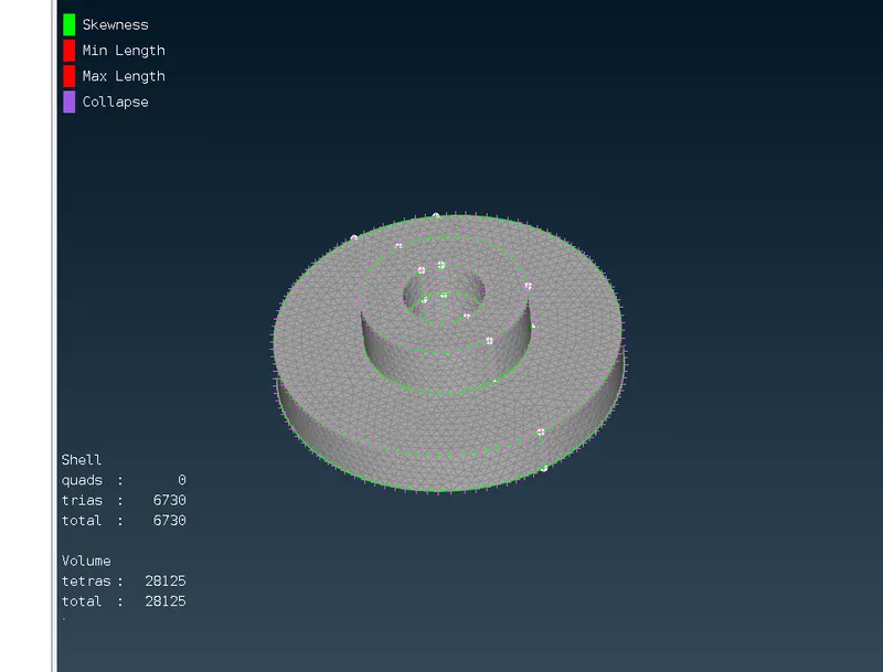
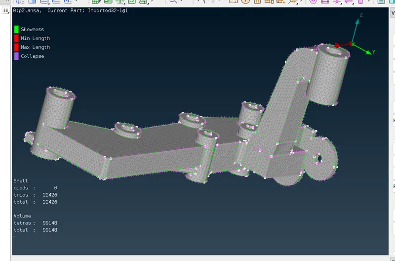
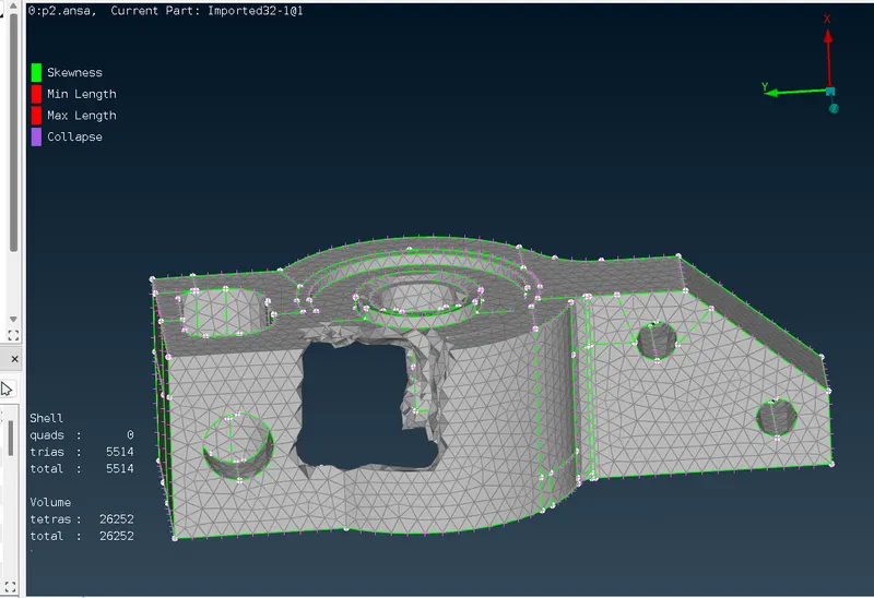
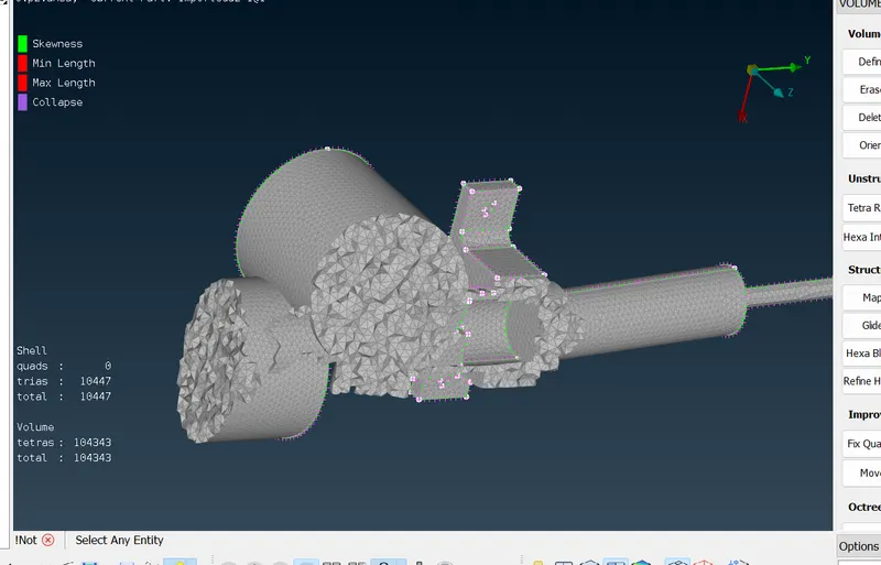
- Thus the parts having non uniform thickness are meshed properly along with proper quality criteria.
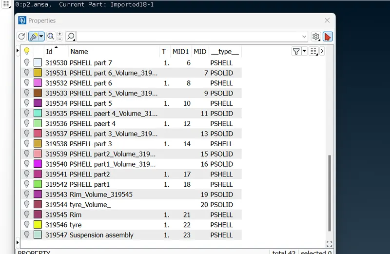 created properties.
- Now for the parts having uniform thickness, we do geomtry check and cleanup respectively.
- Extraction of mid surface topo deck>face>midsurface>offset>create .
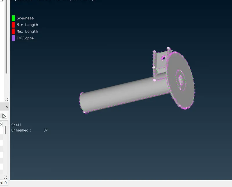
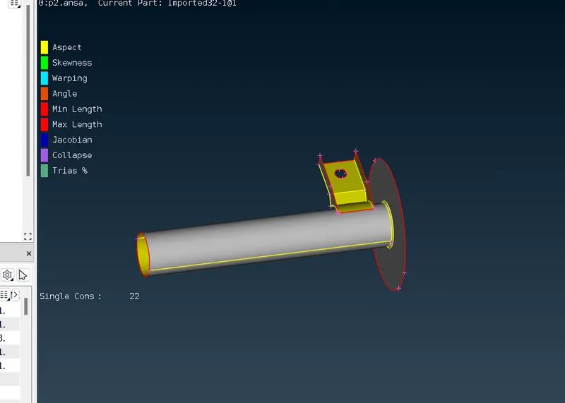
- Give the mesh and quality parameters from the question . perform 2d mesh mesh deck>mesh generation>best>ok. Improve the mesh flow by mesh deck>shell>reconstruction/smooth option availaible. Avoid off elements and chekc for quality failure. Give the thickness to the elements by going to property manager or mesh deck>grids>thickness>slect the elements. To view the shells as solids go to quality parameters> presentation parameters>click yes to view as solid.
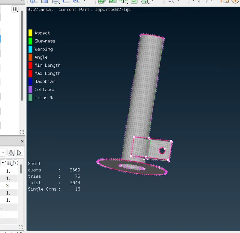
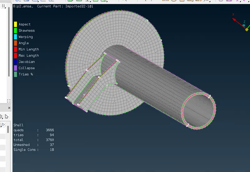
- Thus the parts are now meshed respectively , we go for connections.
- Creating weld connecton to connect the part as shown in figure.
-
FOR CREATING SEAM WELD ,
- Create a curve by using the feature2 curve Mesh>Perimeters>Feat2Curve option and convert the curve line into seam line
- Go to the connection manager and we have to select it.
- We have to select the PID’s(P1,P2) for the parts we connecting.
- Fe representation - Overlap Shell (For Parallel Surfaces) or Y-joint Shell ( For Perpendicular Surfaces)
- We have to provide the Search distance based on distance between the parts.
- We have to choose the Proper base sheet on which the weld is going will be done
- We have to provide the width value as the target element size. here the value is 5
- Create weld property.
- Say apply and realize it.
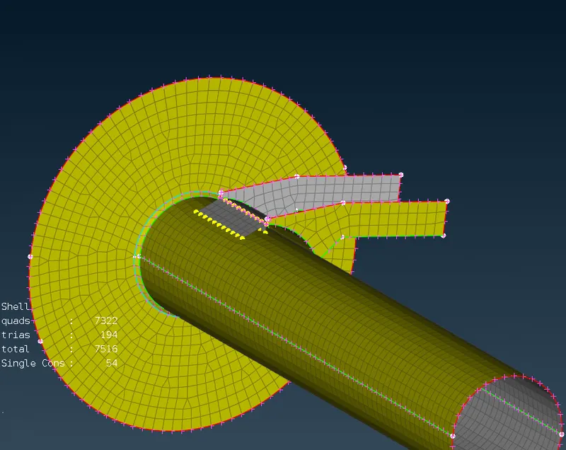
- Creating bolt connection
- Go to nastran deck> elements>rbe2>many modes.
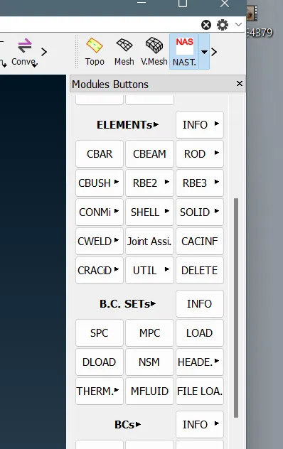
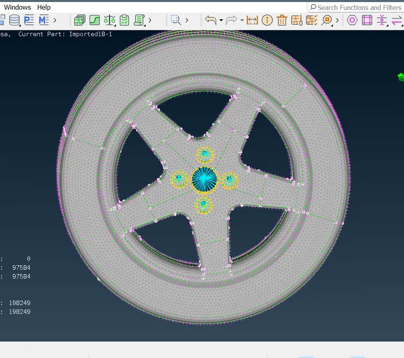
- Select the nodes around in a circular path and double click it will automatically create master node at the centre .Give the required data and create rbe 2 elements . Similarly create master node on the parrallel side . now connect the both master node with two noded rbe 2 element and u get .
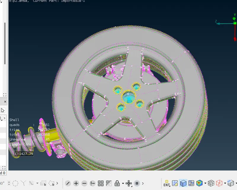
- For creating 1d element for the spring , create curves topo deck>curves>middle>create> and connect the curves. create COG for the orientation purpose. go to nastran deck>elements>pbar>create .
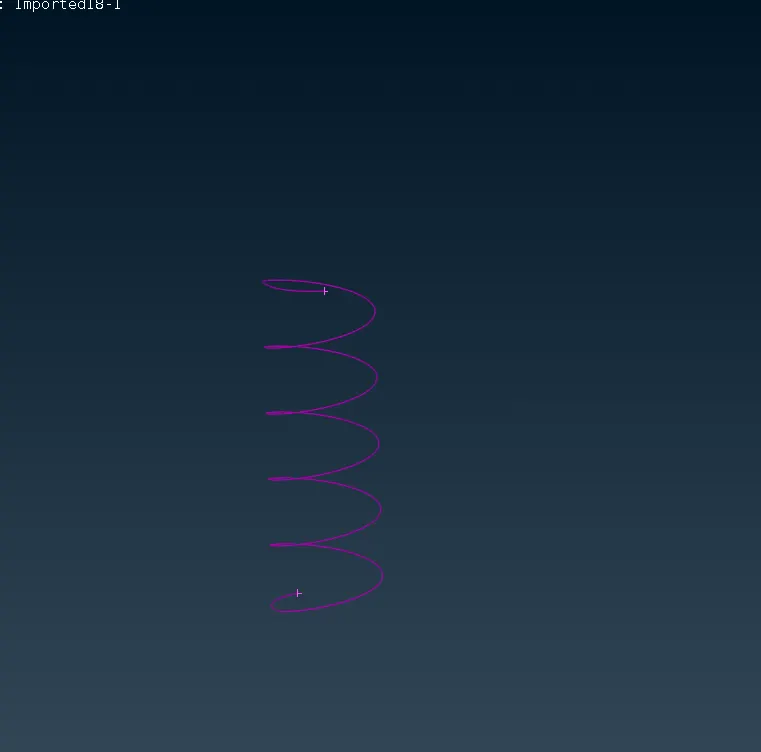
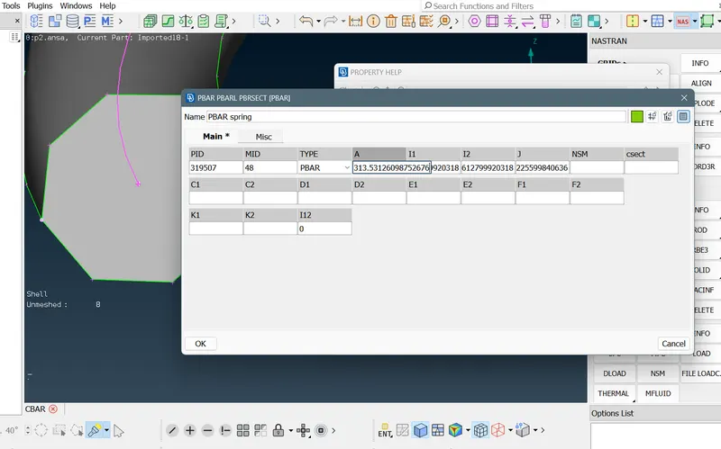
- Giving the required dimentions and values we create the 1d element and we get,
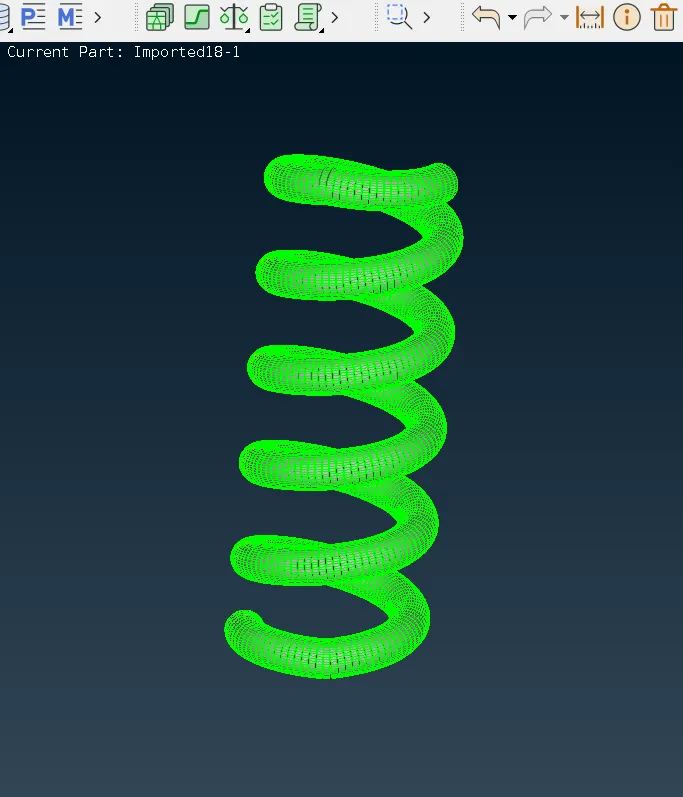
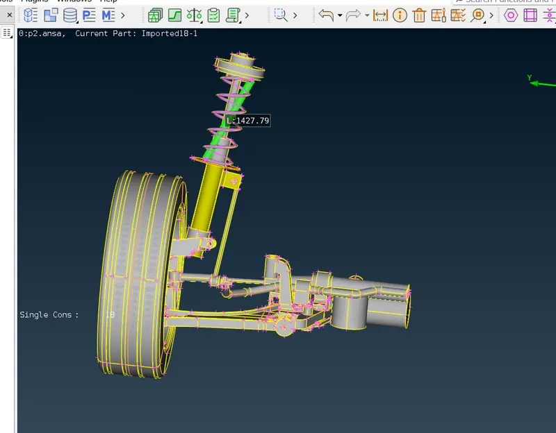
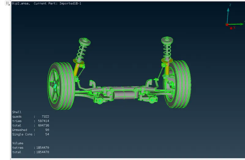
- At last perform Symmetry command to reflect the half finished model to the other side,
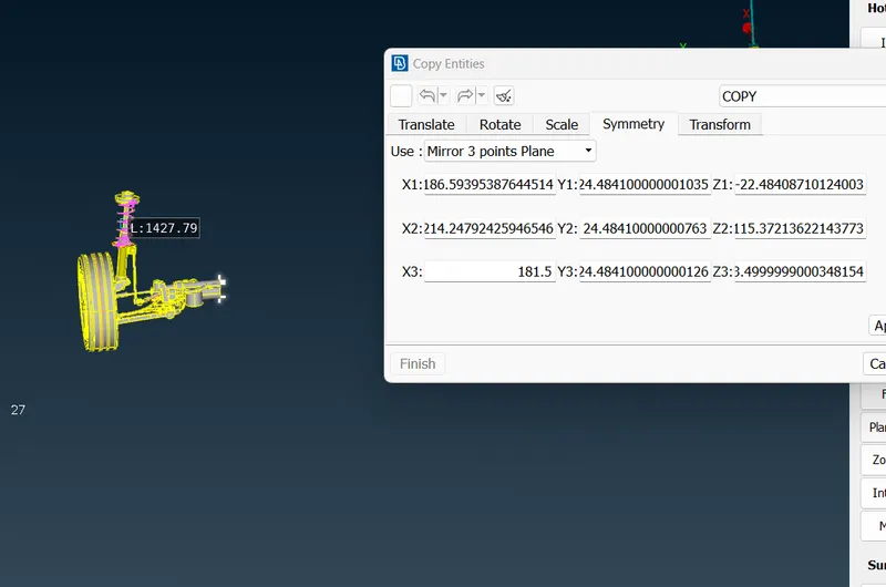
- go to transfrom>symmetry>3 axis point and we get,
CONCLUSION:
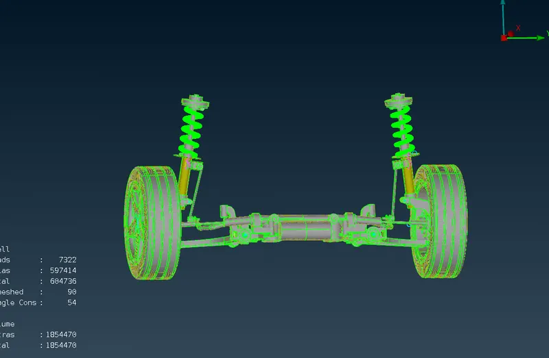
The given suspension model is meshed with the given quality criteria . In addition to that appropriate connections are done to connect the component .
FINAL MODEL:
LEARNING OUTCOMES:
- Creating 1D element on spring geometry.
- Giving prorper connections to the geometry.
- Understanding the thickness of different component to choose type of meshing method on it.
- Selecting offset and skin option to perform extraction of midsurface.