Week- 5 - Solid meshing
OBJECTIVE:
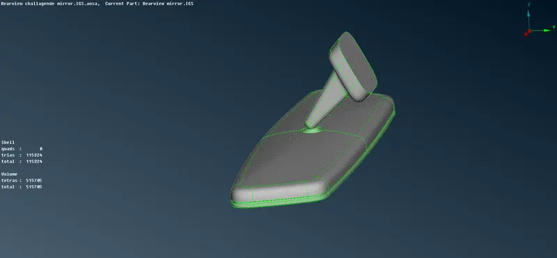
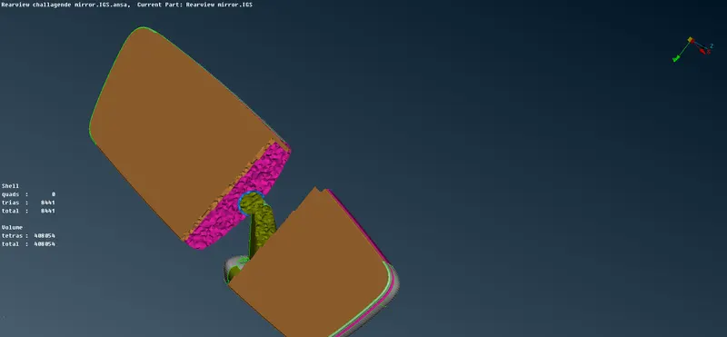
For the given Rear view mirror component, to check for the geometrical errors and mesh the Surfaces with the given 2D element Quality criterias followed by tetra volume mesh .
GIVEN CRITERIA :
|
S.No |
Quality Criteria |
Value |
|
1 |
Target/Average length |
1 |
|
2 |
Minimum Length |
0.5 |
|
3 |
Maximum Length |
2 |
|
S.No |
Quality Criteria |
Value |
|
1 |
Tet collapse |
0.2 |
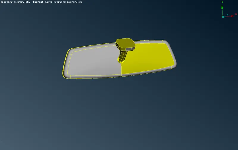
CAD MODEL:
PROCEDURE:
There are 5 basic steps to follow ;
- Geometry cleanup
- Generating 2D mesh
- Pre volume check
- Volume definition
- Generating the 3d mesh
(The above steps are applied for all the parts of the model to solve this challenge .)
- Download the model from the given source and open it on ANSA graphic area.
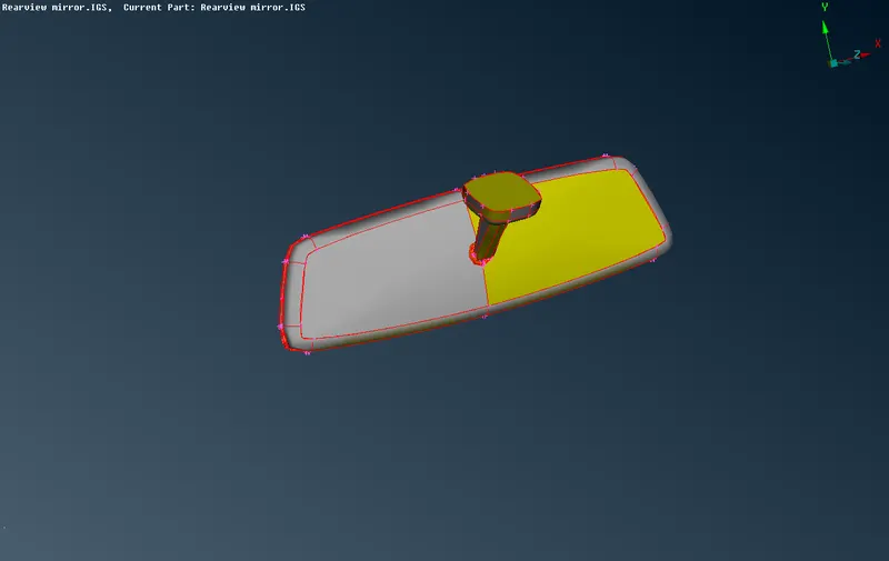
- Check the number of parts on the given component by going on to propery IDs option .
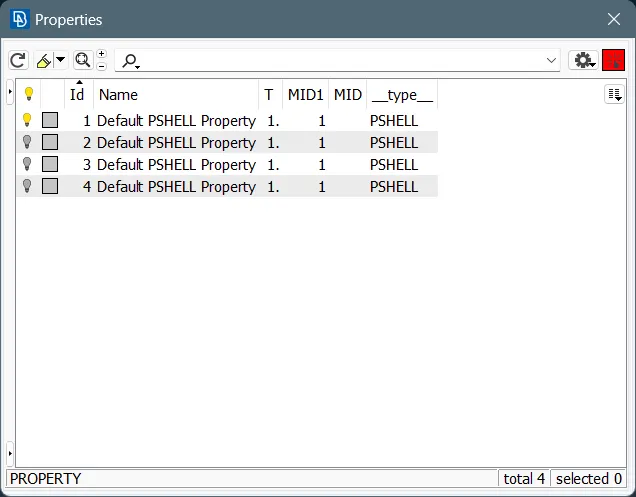
- Individually do the geometry clean up and meshing of parts to get the result .
- Select the first part of the component and give the perimeter length 1 for prorper cons resolution . Next is to do the geometry clean of the component by using Topo and orient option . By topo the single cons are changed to double cons .Mesh deck>perimeters>length>1 .
-
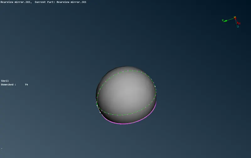 fig1 : part1
 -
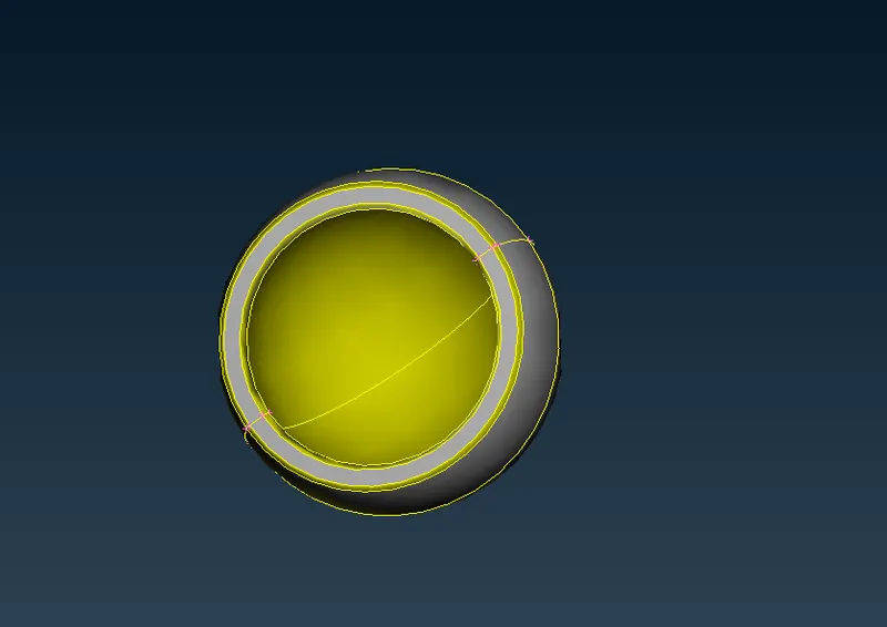 fig2:Topo
 -
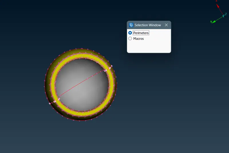 fig3: orient.
 - NOTE : selection of element depends based on surfaces ,as tria for flat surfaces and ortho trias for curved surfaces to get proper capturing of elements.
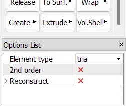
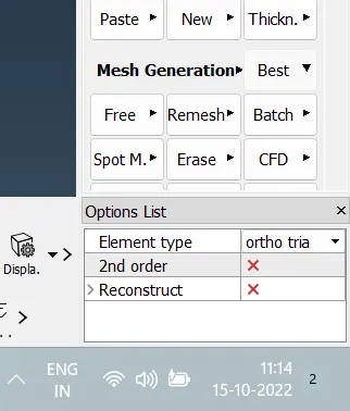
- Check for the geometry clean up . check manager >geometry>select visible>execute.
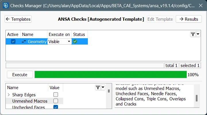
- After the geometry clean up , next step is to create 2d mesh on the surface of the component . firstly give the mesh parameters followed by quality parameters .
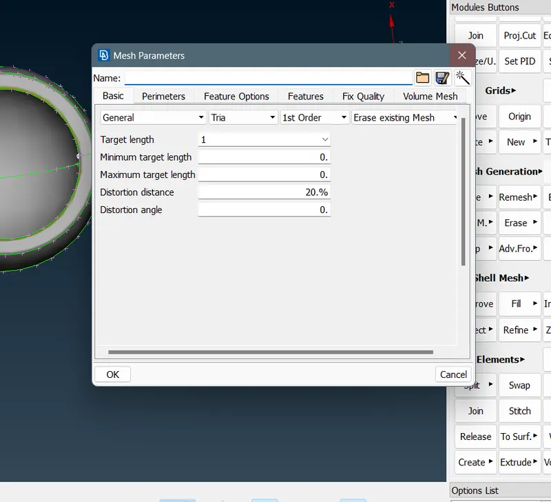 fig4:mesh parameters
 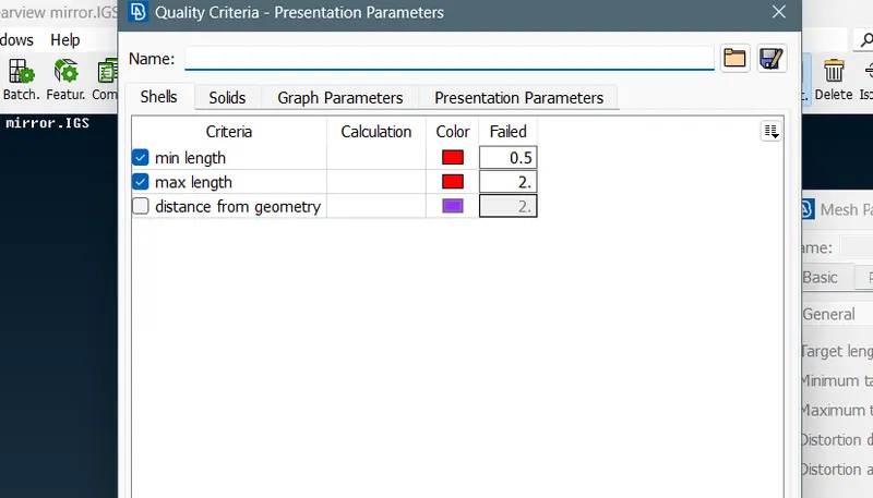 fig5: quality parameters
- Go to Mesh deck >mesh generations >best . Select the component faces and generate 2d mesh .
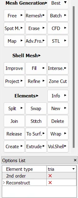 fig 6: mesh deck tab
 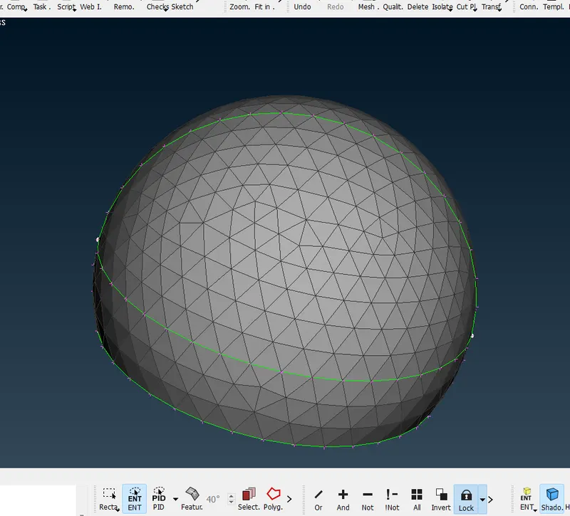 fig7:After mesh
 - Check the quality failure of the generated 2d mesh .
- Get the Pre Volume check by checking unmeshed areas on the component , Penetration check manager>penetration>intersection. The penetration is done to check whether the elements are intersection on eachother. Also check for single cons and double cons before going to define the volume for the part .
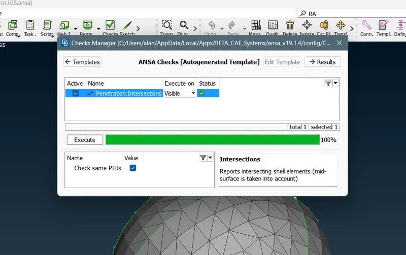 fig8: penetrations.
- Now defining the volume for the given part . go to volume deck>volumes>manual>select visible>ok.
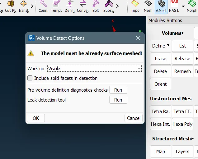
- go to unstructured mesh >tetra rapid and select the visible part and mesh . Thus u get volume mesh for the tetra component by converting 2D tetra mesh to 3D tera mesh .
-
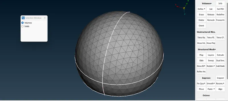 fig9 :tetra rapid
 -
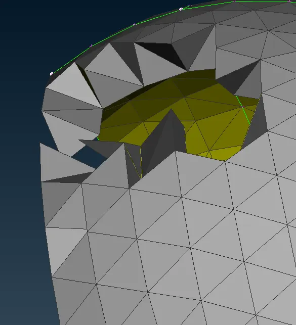 fig10 volume mesh
 -
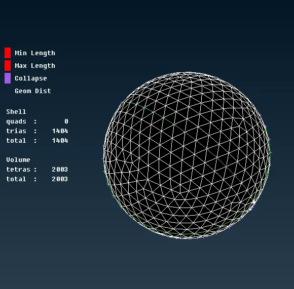 fig11 :quality criteria .
 - Do the check for tet collapse of the part .
- Thus the part 1 is completed with five basic steps .
- Similarly the remaining part is done one by one with similar steps .
- Go to prorperty id and show only the second component.
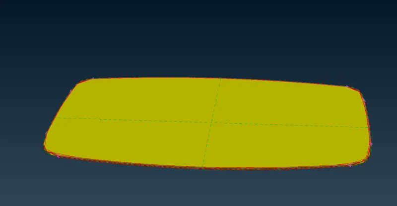 fig12:part2
- The above model undergoes geoemtry clean up and meshed to generate 2D elements.
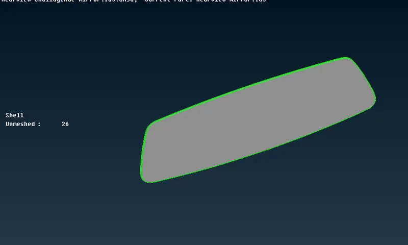 fig13: cleanup part2.
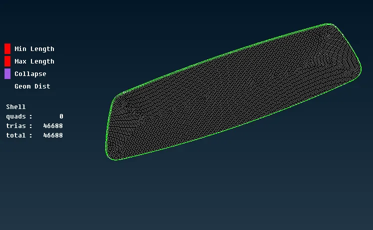 fig14: mesh and quality check .
- After meshing the component it is then checked for penetration and intersections.
- In defining volume , we create and define different volume property card for different parts.
-
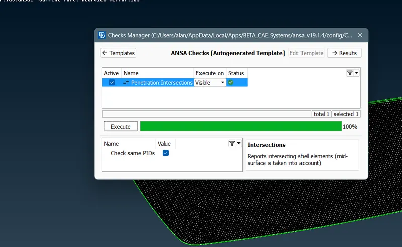 fig 15: check part2
 -
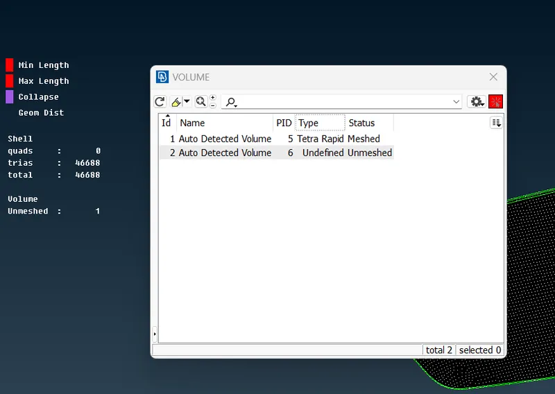 fig16: volume property.
 - Converting 2d elements to 3d elements by using tetra rapid command from volume deck and check the element failure .
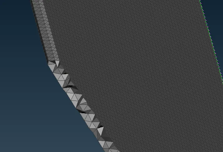 fig17: solid tetra mesh of part 2.
- Go to prorperty id and show only the third component.
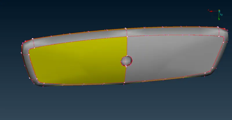 fig:18
- The above part undergoes topo clean up , orient and geometry clean up checks. It is then meshed to create 2d elements . the generated 2d elements are further checked for the quality criteria.
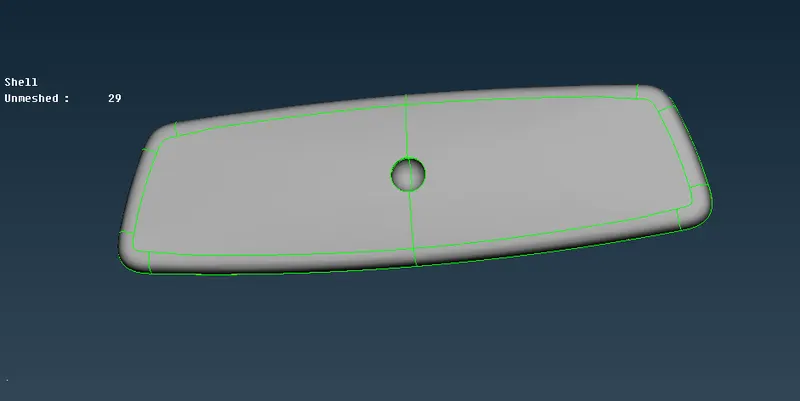 fig19: geometry clean up (topo)
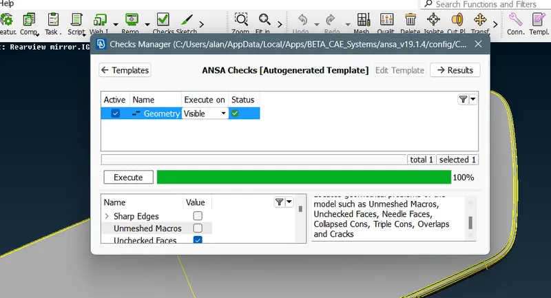 fig20: Geometry check
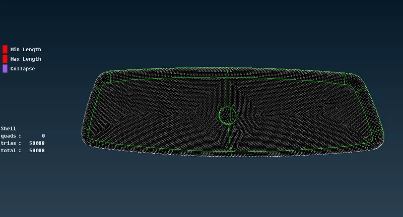 fig21: Mesh and Quality.
- Defining third property volume for the part .
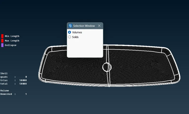 fig22: define volume.
- Meshing the 2d trias to 3d trias .
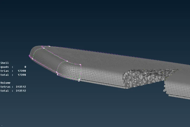 fig 23: 3d tetra element .
- Go to prorperty id and show only the fourth component.
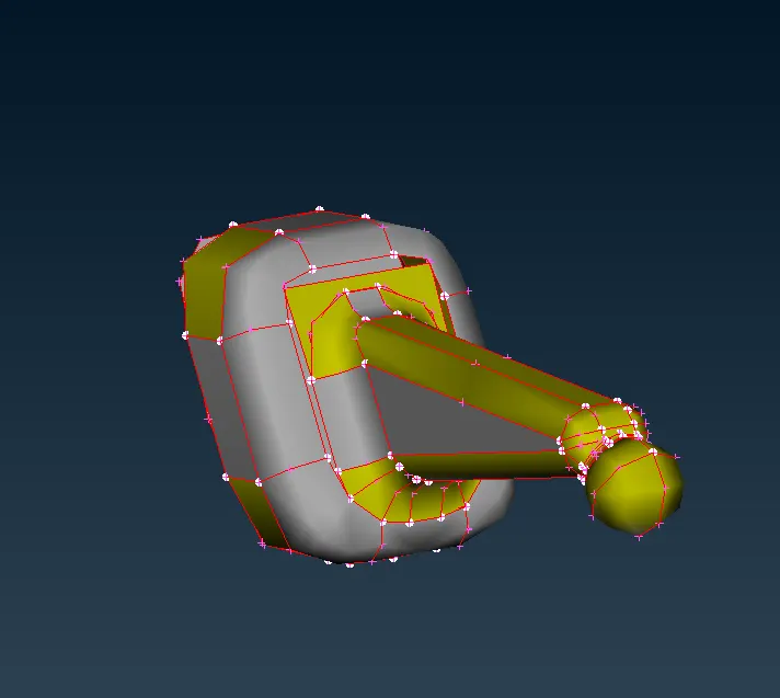 fig 24: part 4
- Firstly the cons resolution is done followed by the connections of the cons by topo , it is then checked for geometry checks .
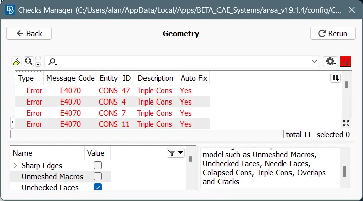
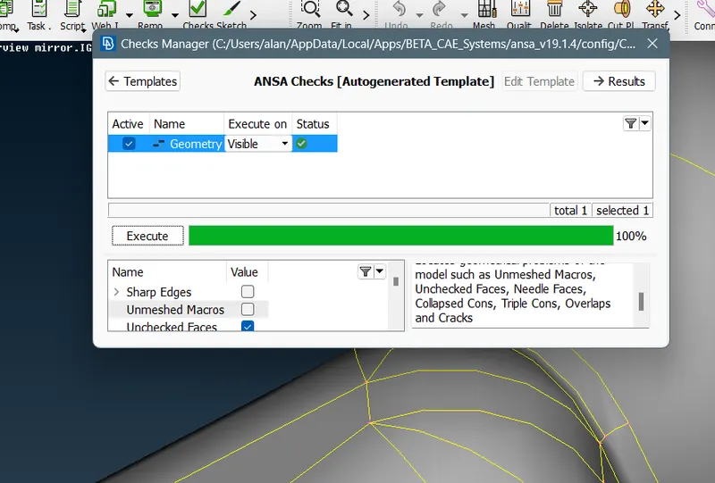 fig 25 : check managers.
- The above part is meshed and the pre volume check is performed .
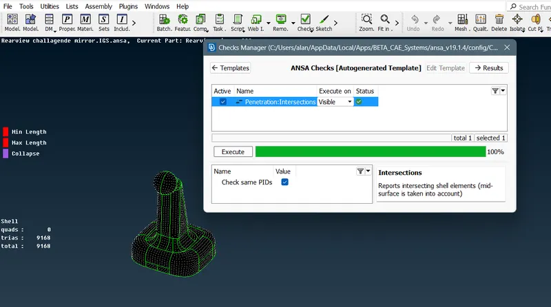 fig26 :penetrations check and meshed part
 - The fourth volume property is defined for part 4.
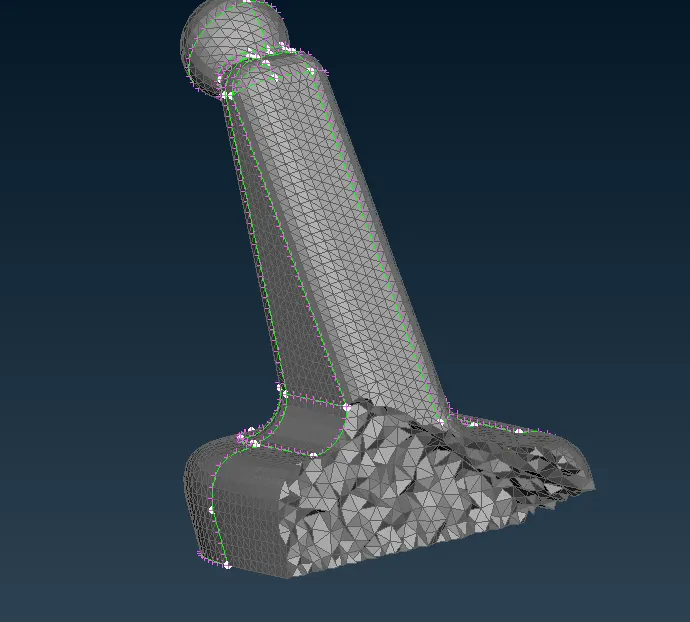 fig 27 : Final image of part 4 volume meshed .
conclusion:
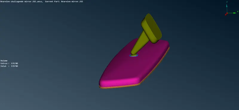
The given CAD model is meshed properly with proper steps respectively to get tetra solid mesh . The geometrical errors are solved by geometry clean up and check managers . The generated mesh elements pass the given 2D and 3D element Quality criterias.
FINAL MODEL:
LEARNING OUTCOMES:
- Conversion of 2D tetra to 3D tetra elements
- Solid meshing
- Selection of tria elements or ortho trias for generating 2d elements.
- Different types of geometry checks on component
- Defining volume to parts.