Week 6-Meshing of Hood Challenge
OBJECTIVE:
To take the mid surface for all the given components after checking the geometrical errors and mesh the mid surface with the given element Quality criteria.
GIVEN:
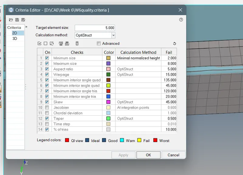
The quality criteria for 2D elements.
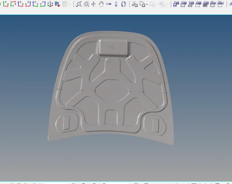
CAD MODEL:
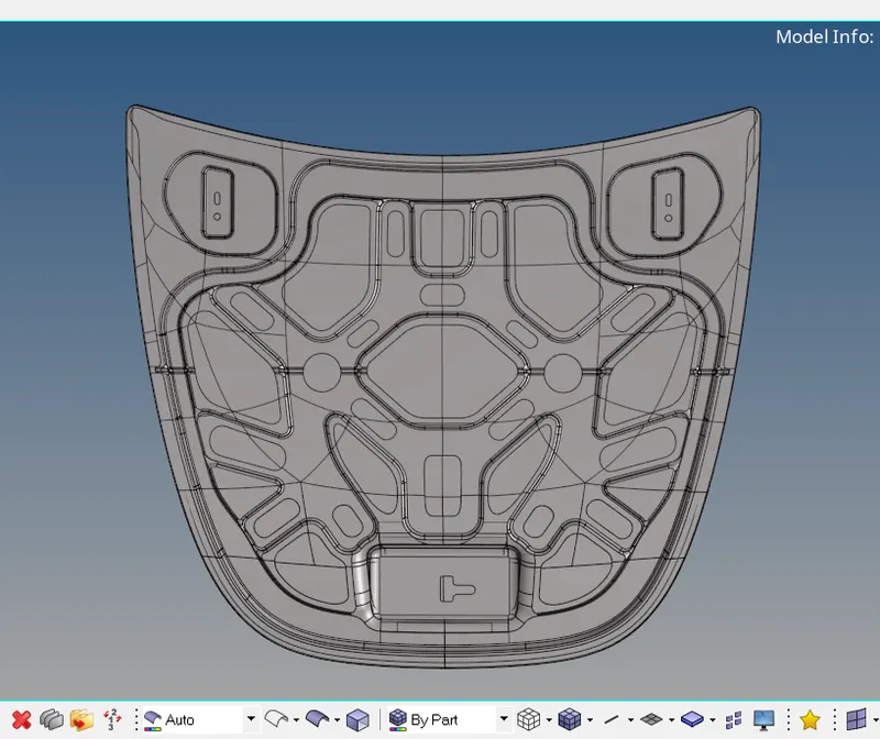
PROCEDURE:
- Import the downloaded model on the graphic area. File type is in IGES fromat .go to>Import solver>Import geometry>IGES from option >Import. Delete the solids if present .
- Once the model is imported check for the number of components of the given model .
- Individually go for Geometry cleanup and meshing the component. Delete the unwanted geometry on the component. The first component ,
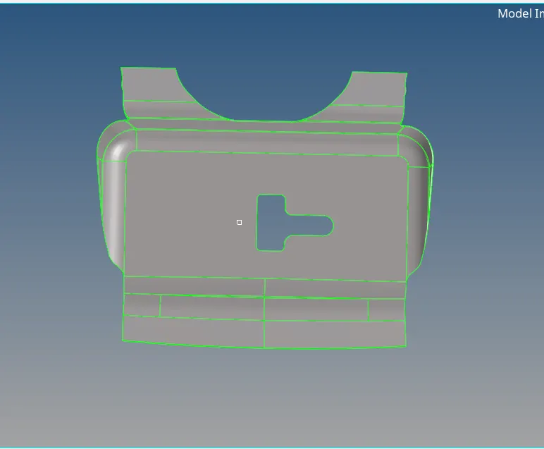
- By checking the thickness we understand whether it has uniform thickness or not . After checking we see that it has uniform thickness . Each component is measured one by one and values .
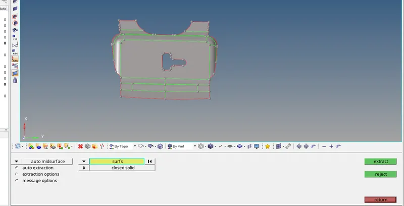
- Since it has uniform thickness we go to >geometry>midsurface>auto midsurface>apply to extract the midsurfacing. After taking the midsurface of the components always create new component to avoid any confusion. right click over the name >rename > or choose the color to assign .
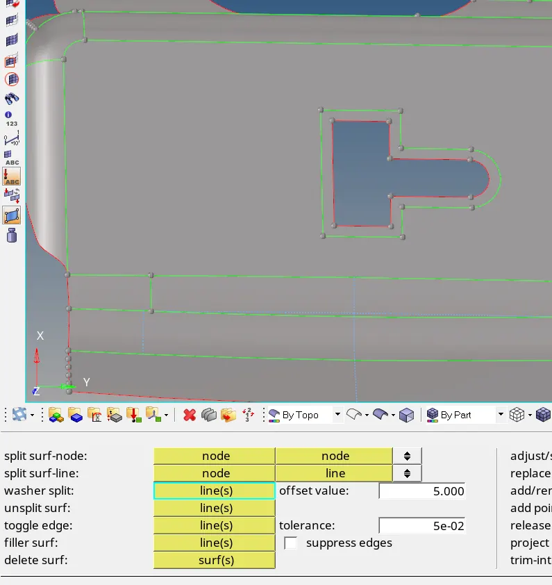
- Do the auto cleanup after generating the midsurface go to quick edit to create washer splits ,
- Next step is to assign mesh parameters and the quality criteria.
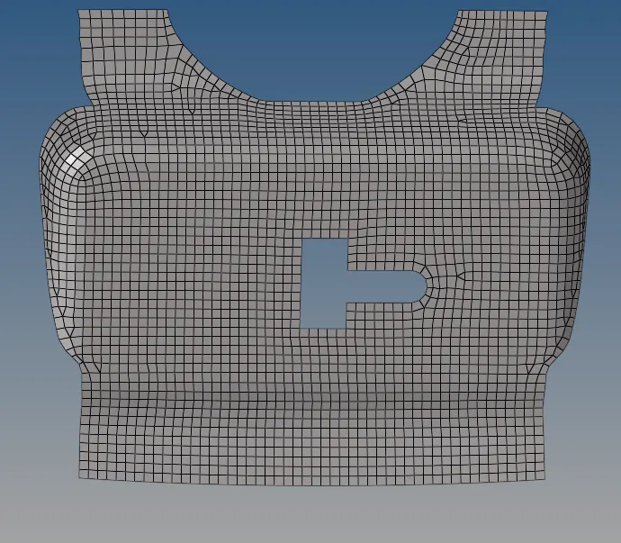
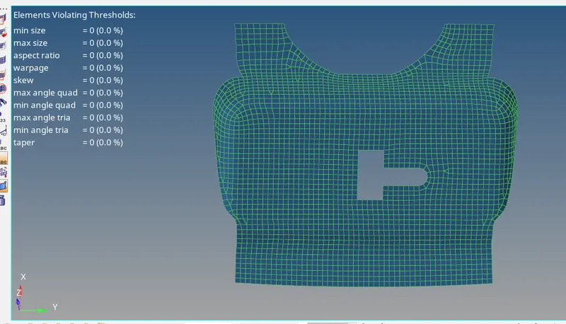
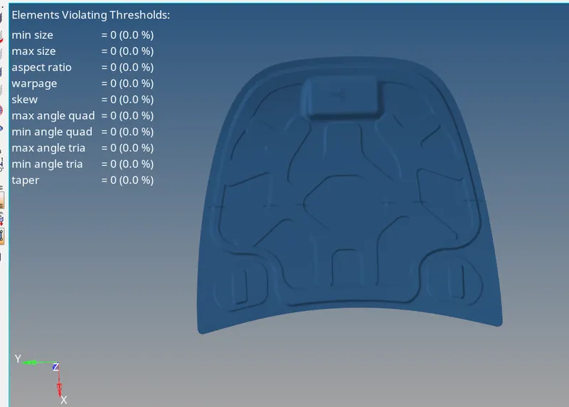
- After the mesh , solving the violating elements , features capturing, the mesh flow we get,
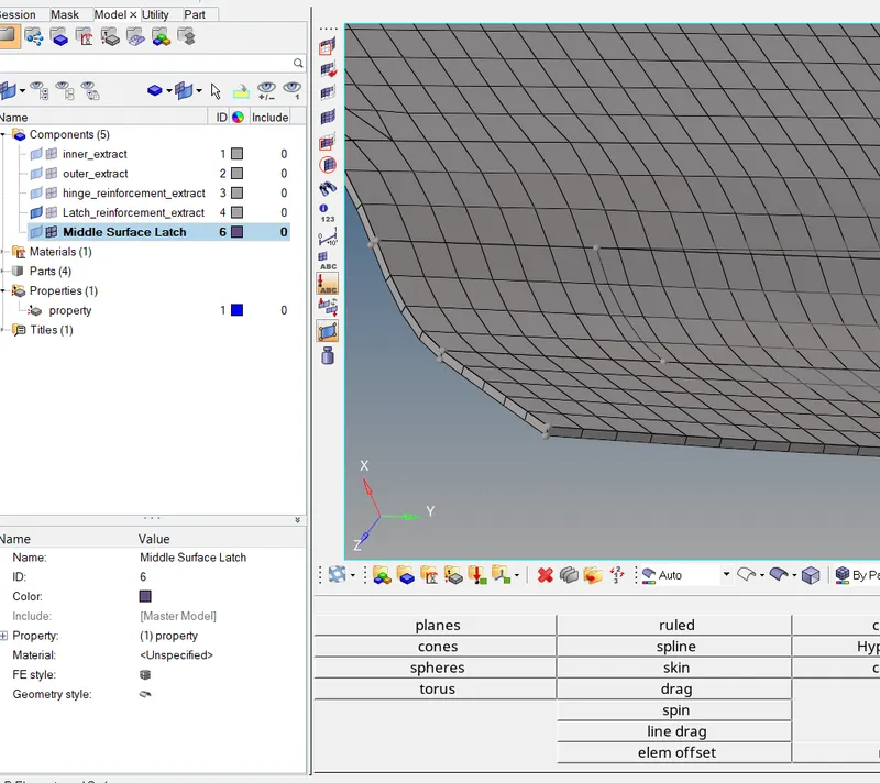
- Assigning the thickness,
- For next component number 2 we follow the same procedure
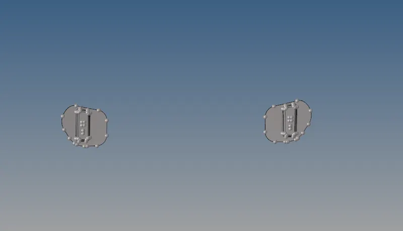 >>>Midsurface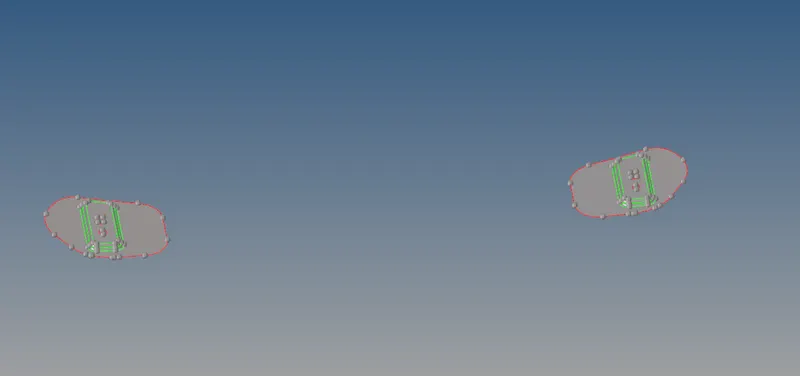
- Meshing the surface with the given mesh unit 5mm. go to 2D>automesh>option surface>give element size>select the mesh type>select the surface of the component>mesh.
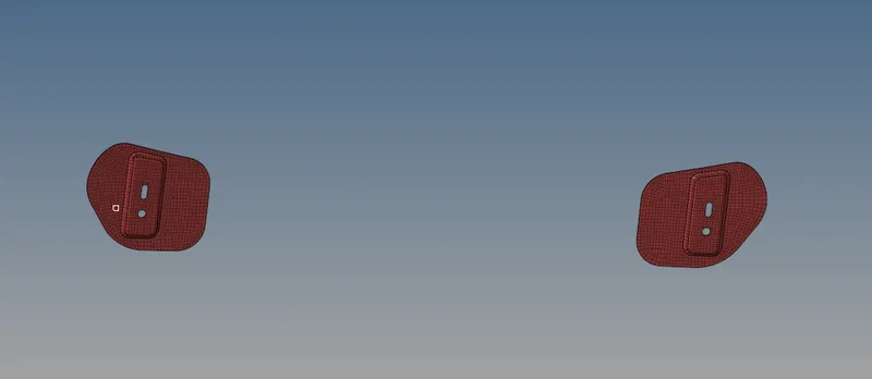
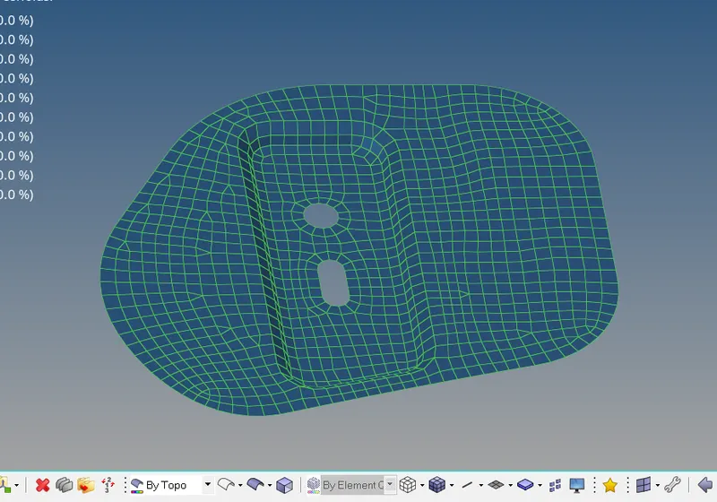
- Repeat the same procedure performed for the component 1 to the last component of the given model, now for component number 3,
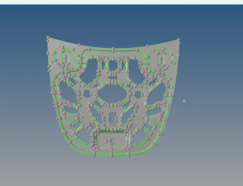
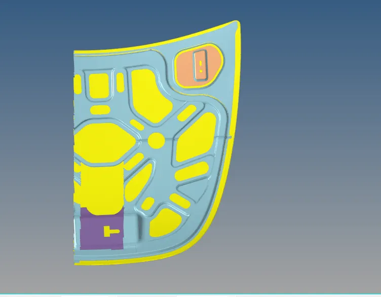
- Since the geometry is in symmetry we create the mid surface in one region and mesh it respectively . Once the elements pass the required quality criteria , the elements are reflected and conneted .
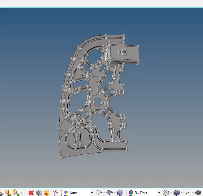
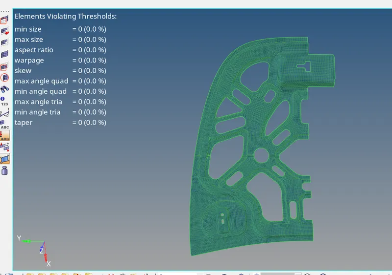
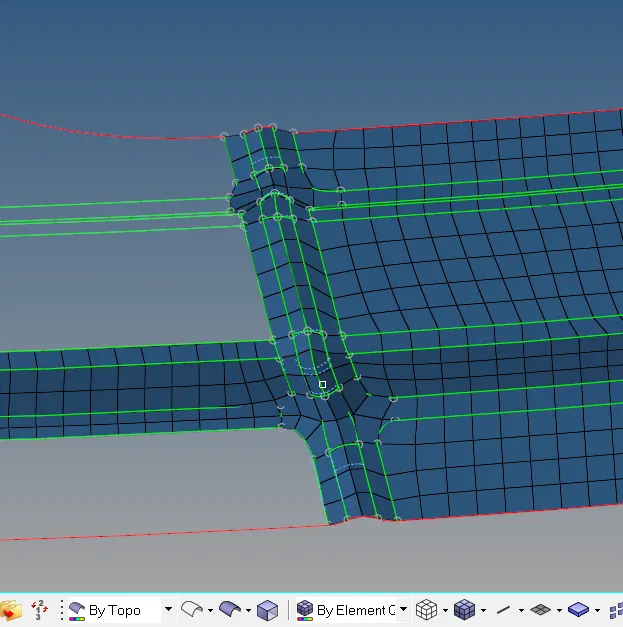 maintaining the mesh flow .
- For the last component, it is similar to the above case of symmetry,
- given,
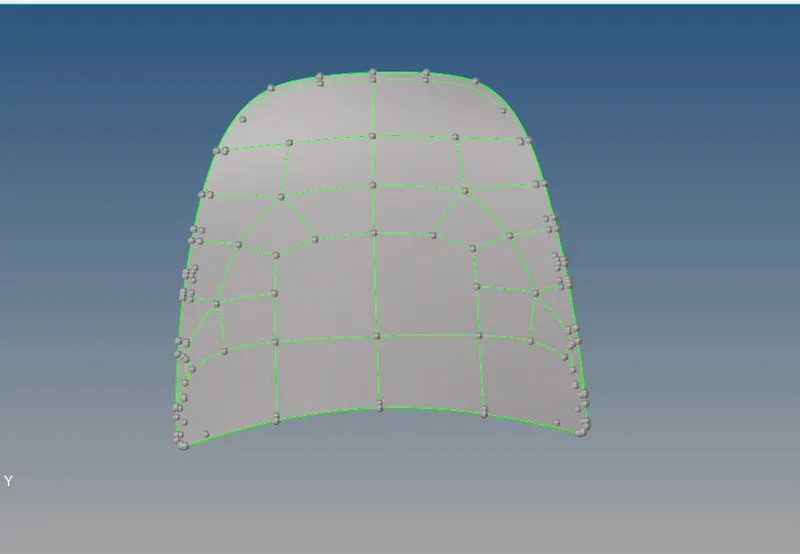
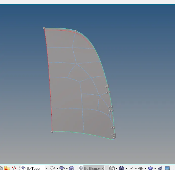
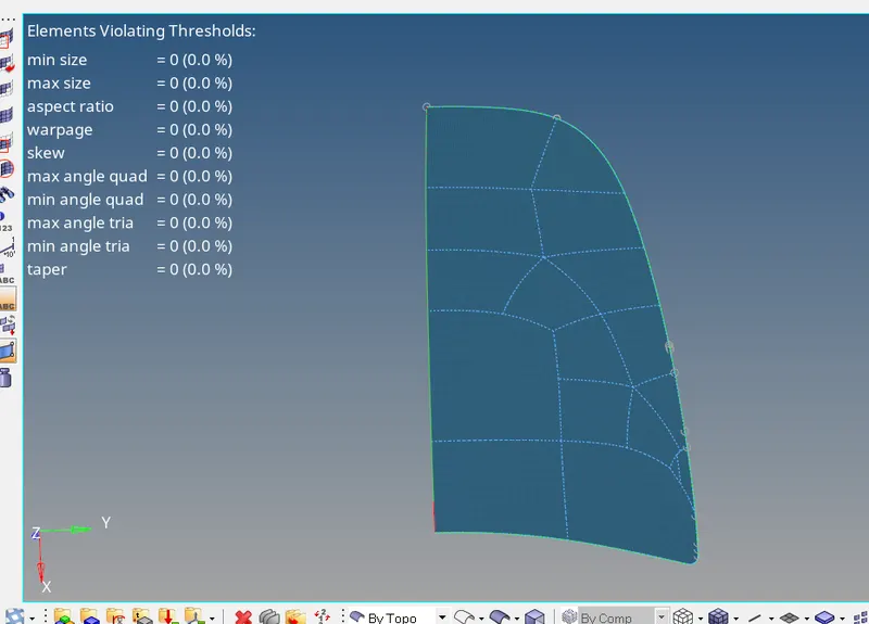
- After reflecting the ,
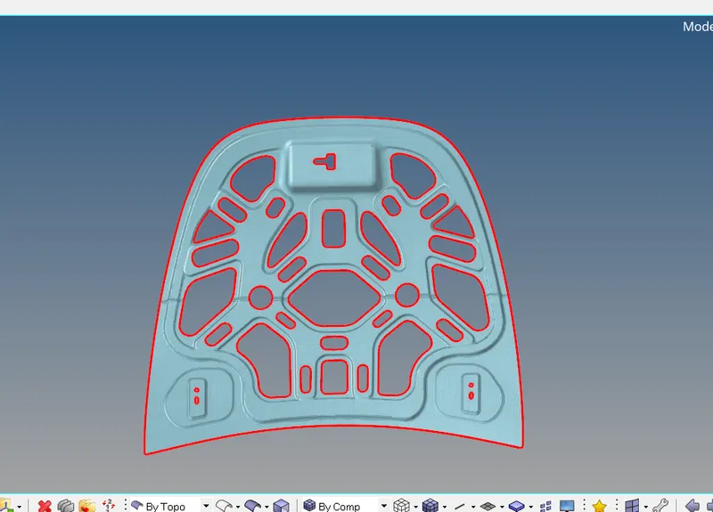
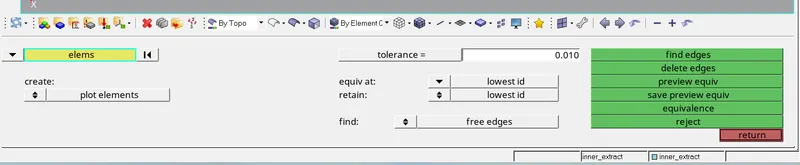
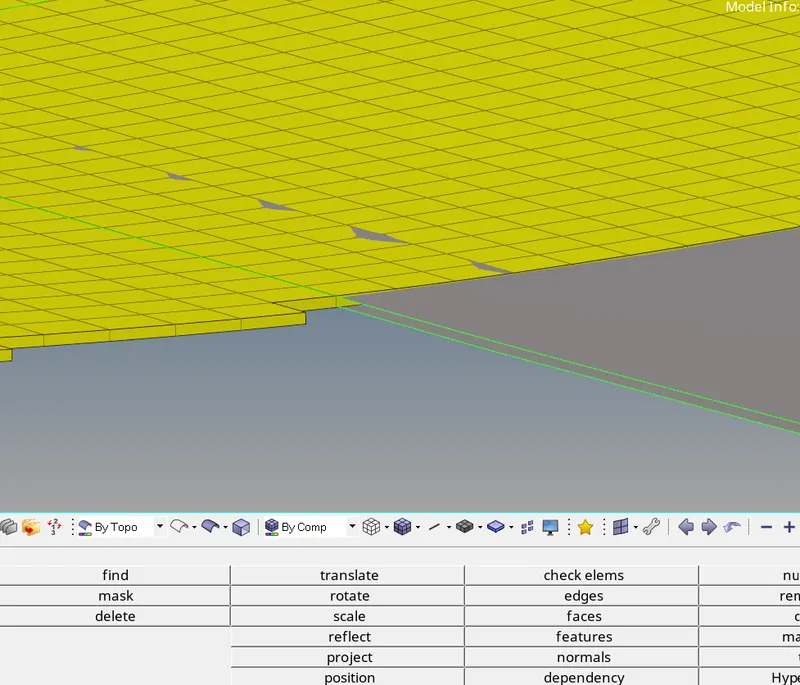
- Make sure there are no free edges go to >tool> edges>select the elements>preview equivalence>equivalence.
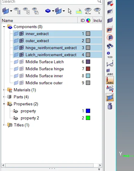
- In the final stage assign the thickness of the given model for each components.
- property,
CONCLUSION:
Thus the given component is meshed with the element size 5 units.
FINAL CAD IMAGE:
NOTES:
- refer the file W6.hm