1D Element Creation Challenge
OBJECTIVE:
Mesh the Given component with the Size of 5 Units. Create 1D elements on the following component with given cross-section and DOF,
a. Rod element:- Translational DOF should be Constrained with RBE2 link
Cross-Section: BOX- Dimension a= 12 mm
dimension b=10 mm
Thickness t= 0.75 mm
b. Beam element:- All DOF should be constrained with RBE3 link
Cross-Section: I Section- Dimension a= 8 mm
Dimension b= 10 mm
Dimension c= 8.5 mm
Thickness t1= 0.75 mm
Thickness t2= .6 mm
Thickness t3= .6 mm
c. Bar element:- Constrain only x and y DOFs With RBE3 link
Cross-section: X section- Dimension DIM1= 5 mm
Thickness DIM2= 1.2 mm
Dimension DIM3= 10 mm
Thickness DIM4= 1.2mm
d. & e. Apply the mass of magnitude 10 with the RBE2 link
f. Join the two components with Spring elements .
CAD MODEL:
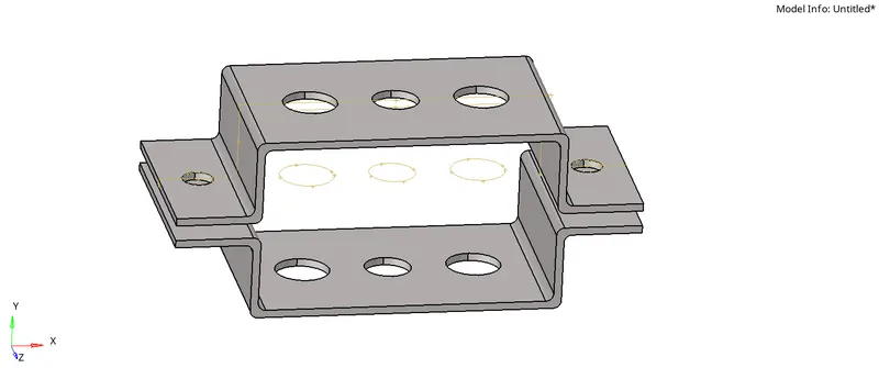
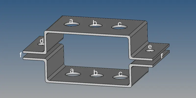
AIM:
1. Mesh the Given component with the Size of 5 Units.
PROCEDURE:
- Import the downloaded model on the graphic area. File type is in IGES fromat .go to>Import solver>Import geometry>IGES from option >Import.
-
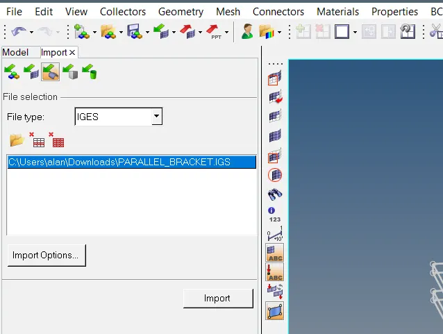 .
. - Delete the unwanted geometry on the component.
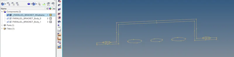
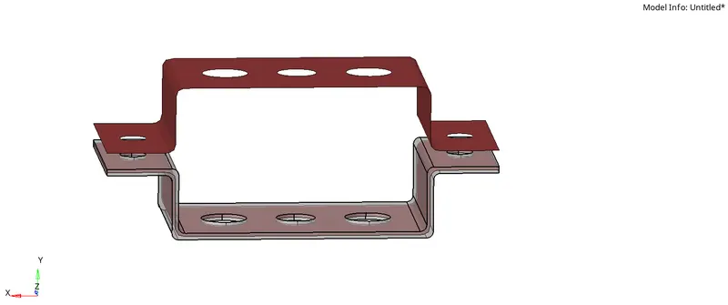
- As the midsurface of the given component is uniform, we take midsurface of the whole component . go to >Geometry>midsurface>auto-midsurface>select the component>extract.
-

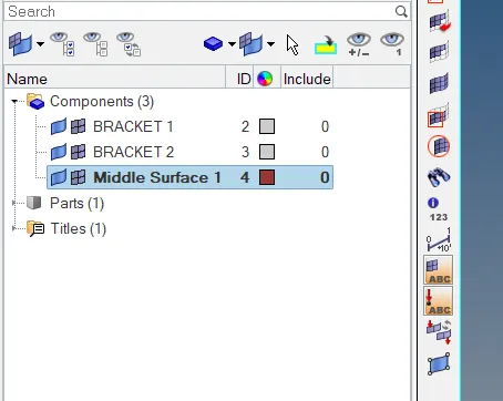
- After taking the midsurface of the components always create new component to avoid any confusion. right click over the name >rename > or choose the color to assign .
-
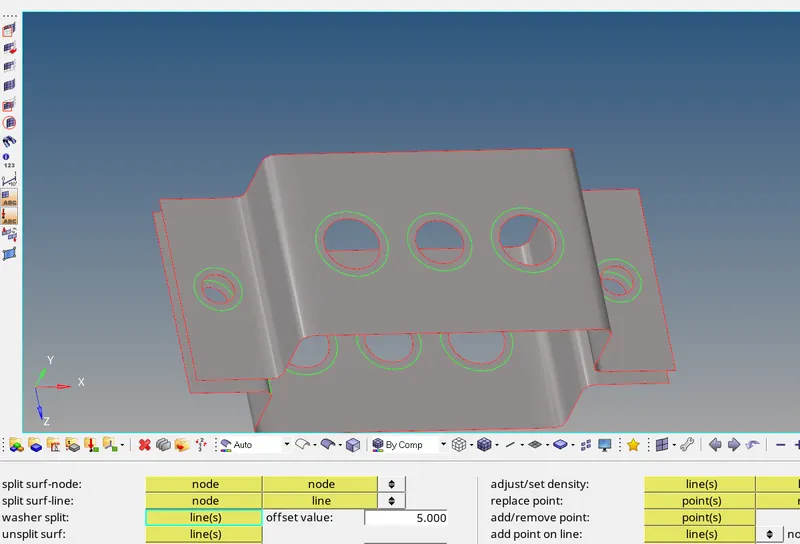
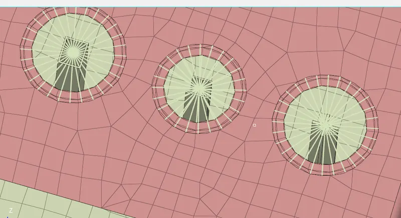
- We create washer split around the surface with the help of quick edit tool. Geometry>quick edit>washer split>give offset value>select the edge. To get proper mesh around the edge or circular geometry by giving the offset value 5 units.
-
- Meshing the surface with the given mesh unit 5mm. go to 2D>automesh>option surface>give element size>select the mesh type>select the surface of the component>mesh. Since the mesh type is not given we choose quads element. By selecting surfaces one by one we get the meshed surface.By increasing the node and decreasing we get proper mesh manually.
-
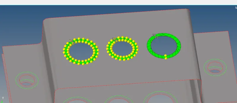
- Above component is meshed with the element size 5 units.
-
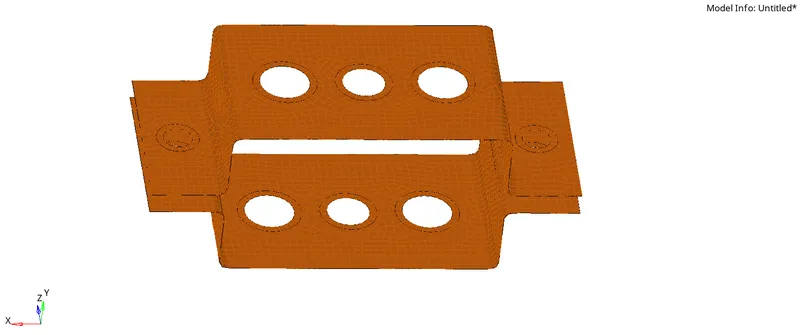
Conclusion:
Thus the given component is meshed with the element size 5 units.
AIM :
2. Create 1D elements on the following component with given cross-section and DOF.
PROCEDURE:
- Through the given cad model in question we are given different section named by a,b,c,d,e,f, and its property ,material , element along with other requirements.Thus each hole is assigned .
- Hole a,b,c is for the 1-D element Rod,Beam,Bar respectively.
- Creating RBE2 links for hole a , click on the nodes around the hole and create the links. Select calculate node and multiple nodes in the panel as option.Select dof1,dof2,dof3 since it is the translation degree of freedom required, where dof4,dof5,dof6 are for rotational. 1D>rigids>option calculated node>option multiple nodes>select the nodes by path>select element type RBE2>create.
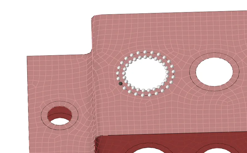

- Similarly we create RBE3 link for the hole b with all DOF. 1D>rbe3>option calculated node>option multiple nodes>select the nodes by path>select all dofs>select element type RBE3>create.
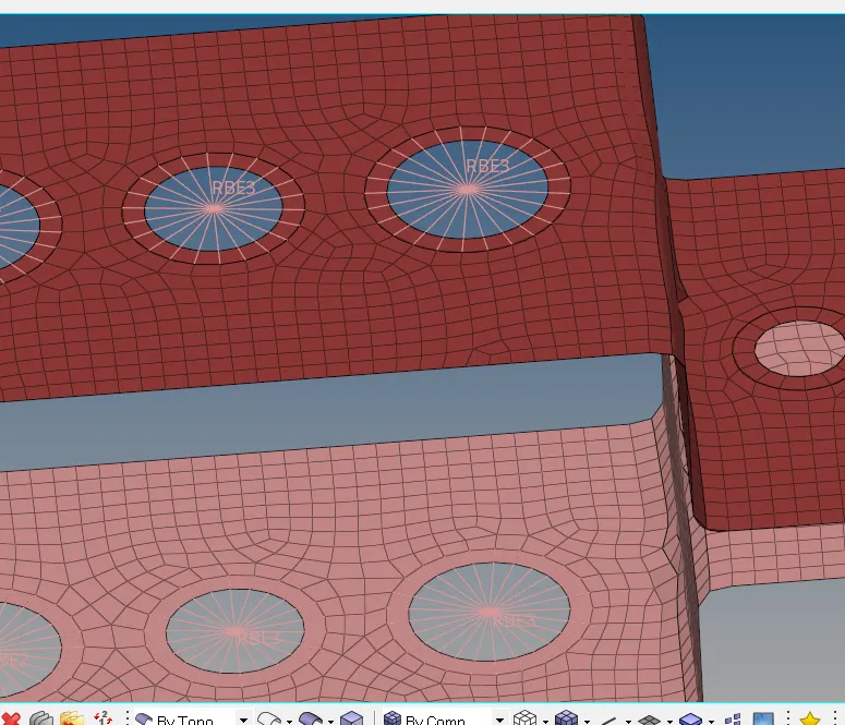

- For hole c , we create RBE3 link with constrain only x and y degree of freedom .1D>rbe3>option calculated node>option multiple nodes>select nodes by path>select element type RBE>create.

- Thus links are created for section a,b,c section.
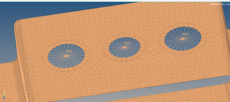
- Now, creating RBE2 link for hole d and e by assingning the mass of magnitude. 1D>rigids>option calculated node>option multiple nodes>select the nodes by path>select element type RBE2>create.
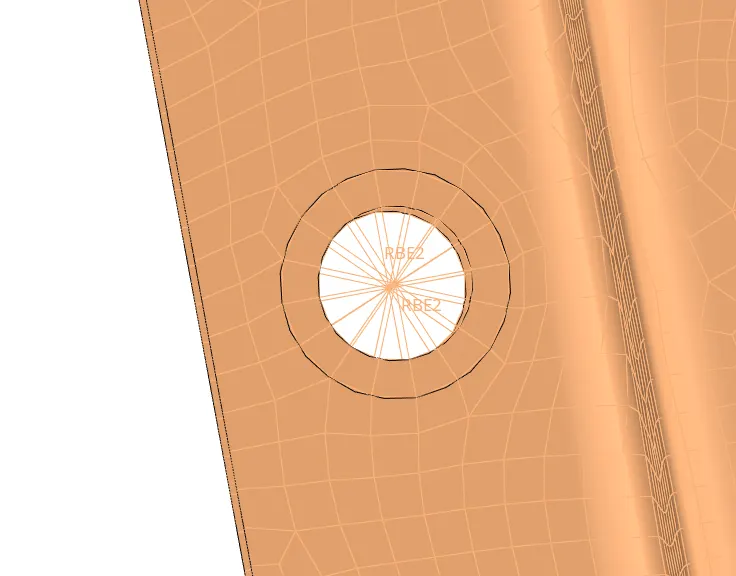
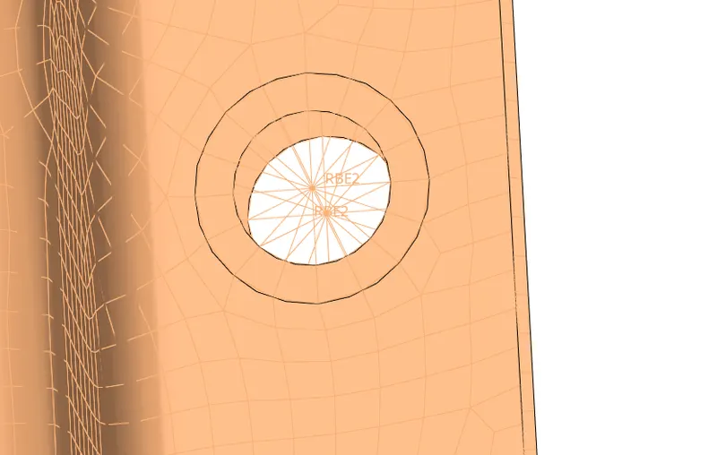
- We add mass to the Rbe2 links on hole d and e . go to 1D>masses>give the mass>select element type>create.

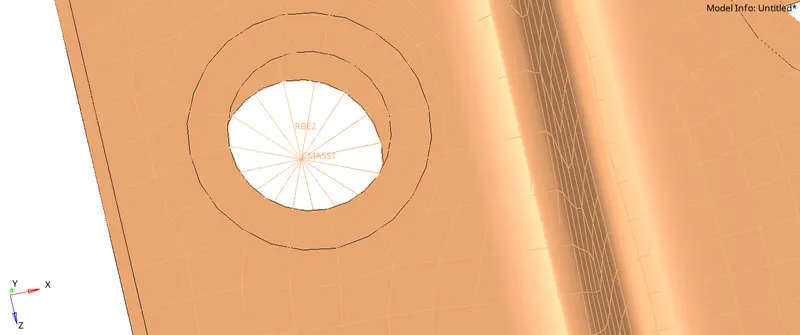
- Joining the two components by using spring elements from the tool panel . 1-D>Spring>select two end nodes>select any dof as per direction required>create both sides.
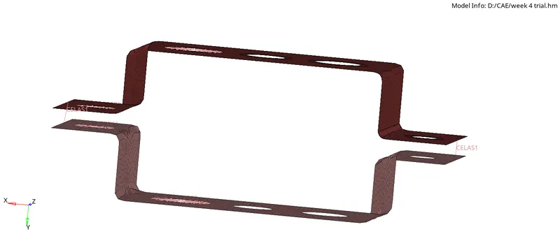
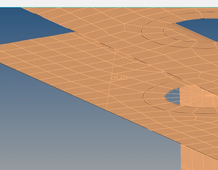
- To create Rod element,select two nodes between two component having RBE2 link on hole a and create . 1-D>Rod> select element type CROD>select two nodes>create.
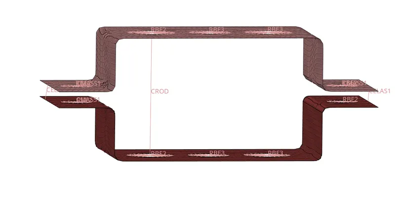

- To create beam element select two end nodes between two component having RBE3 link on hole b and create . 1-D>Bar>select element type CBEAM>select node A>select node B>create.
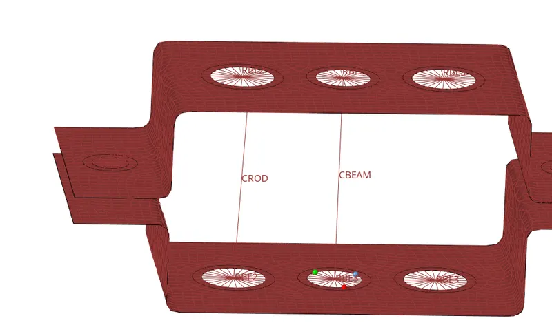

- Similarly we create the bar element on hole c between two components joining the links . 1-D>bar>select the element type CBAR>node A>node B>give the orientation N1N2N3>create.
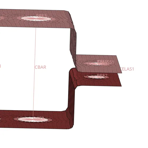

- To create cross section , we use hyper beam tool, as per the given cross section in the question we select the shape for each element respectively 1-D >hyperBeam>standard section.
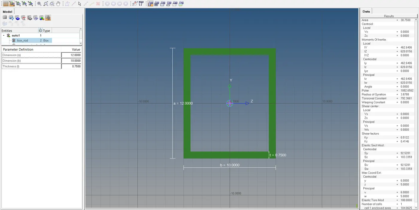
- Select the box section geometry required for the cross-section. Give the dimension a=2 b=10 t=0.75 respectively .
-
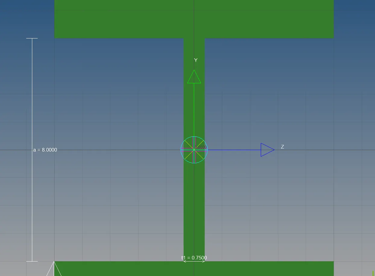
- Create new shape I section geometry for the cross section , give the dimensions on the screen a,b,c = 8,10,8.5 respectively. t1,t2,t3 = 0.75,6,6 respectively.
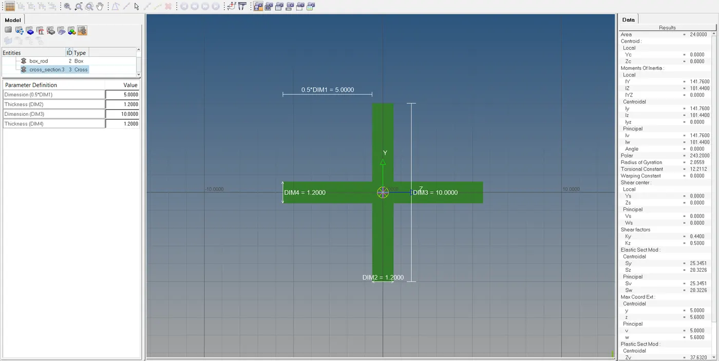
- Create another geometry of shape X geometry for the cross section , give the dimension M1=5 M2=1.2 M3=10 M4=1.2 .
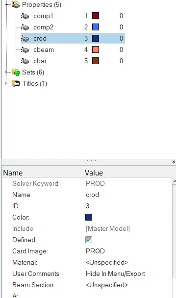
- To create properties for each element for CROD select the card image PROD along with beam section box geometry.
- Similarly we create for CBEAM select the card image PBEAM along with beam section as I geometry.
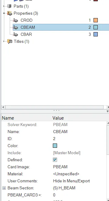
- Now for CBAR select the card image PBAR and beam section X geometry .
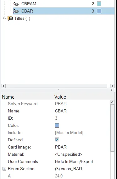
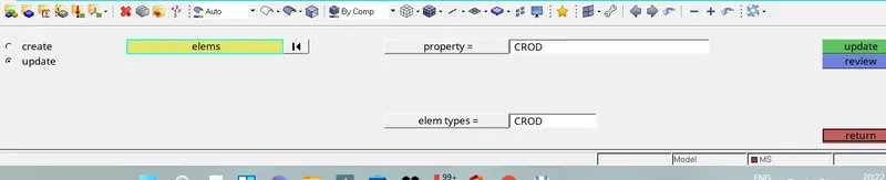
- After the update of the properties to the component , update the elements by assigning the property .
- For CROD go to >1D>Rod >select CROD>property>select the required property>update.
- For CBEAM go to >1D>BAR>property>select the required>update it.
- For CBAR go to >Rod >select CBAR>property>select the required property>update.
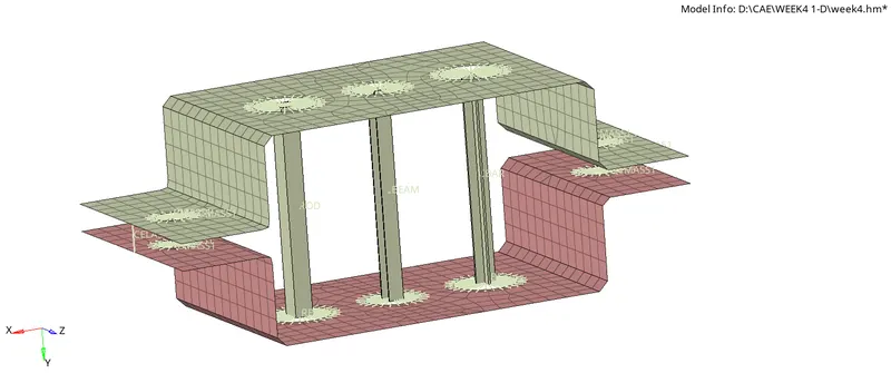
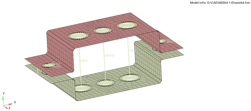
- Refer the below image :

-

- We get the 1-D element with required cross section and degree of freedom .
Conclusion:
Thus 1D elements on the following component with given cross-section and DOF is created.
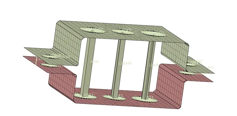
Result:
The Given component is meshed with the Size of 5 Units and 1D elements are created on the following component with given cross-section and DOF.
NOTE
Model files are uploaded with respect to .hm .
MODEL = week4.hm - 433.5 KB .