Week 6 - Creating connection for Rear door
OBJECTIVE:
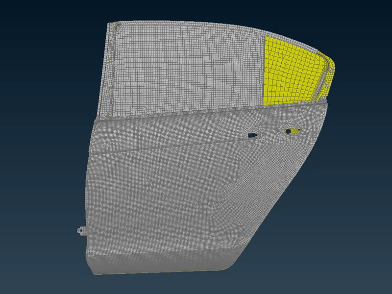
Creating connections to the given Rear door FE model, Create and Apply different PIDs for different components.
FE MODEL:
PROCEDURE:
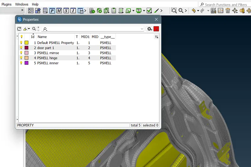
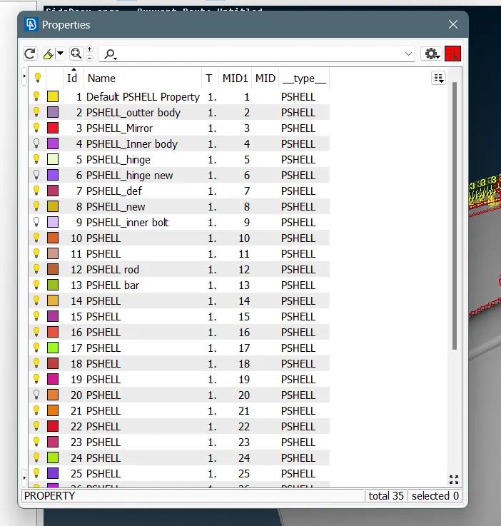
- Before starting the connections we create different property card for the given FE model .
- CASE 1:Creating bolt for connecting the parallel parts. It can be done in two ways .
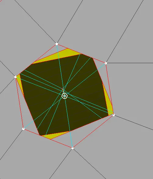
- Create a 3d point by topo deck>cog>point between 6-noded circle .
- Convert the 3D point to a bolt by going to convert option in tool deck.
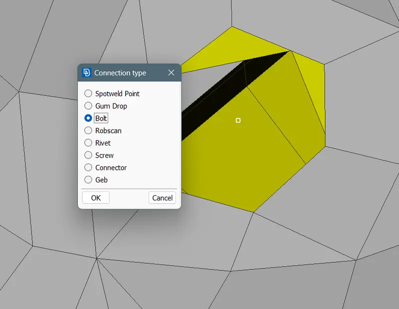
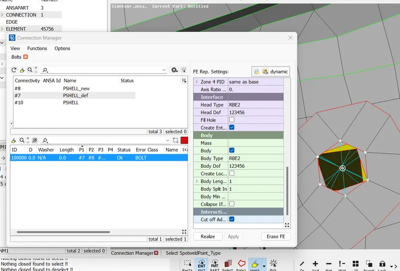
- Go to the connection manager and select Connection Entity.
- We have to select the PID’s(P1,P2etc..)
- Fe representation > Bolt
- Search distance > 20
- Say apply and then realize it.
- Creating bolt mannualy .
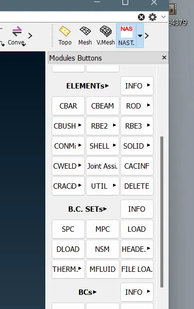
- Go to nastran deck> elements>rbe2>many modes.
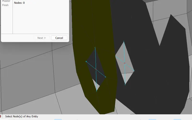
- Select the nodes around in a circular path and double click it will automatically create master node at the centre .Give the required data and create rbe 2 elements . Similarly create master node on the parrallel side . now connect the both maaster node with two noded rbe 2 element and u get .
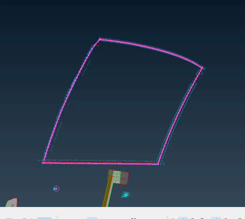
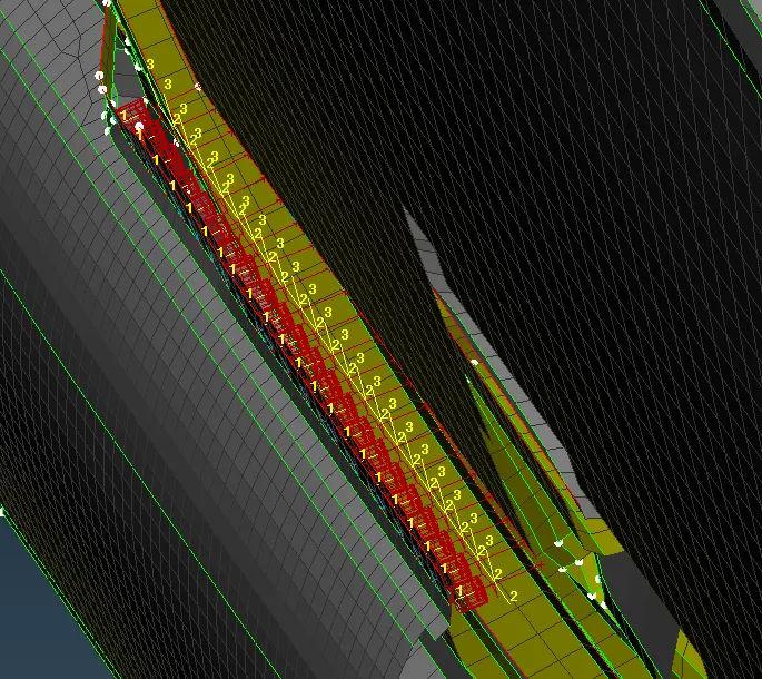
CASE 2 : Creating Cbush element on side door mirror.
- Create a curve by using the feature2 curve Mesh>Perimeters>Feat2Curve and onvert the curve to a spot line.
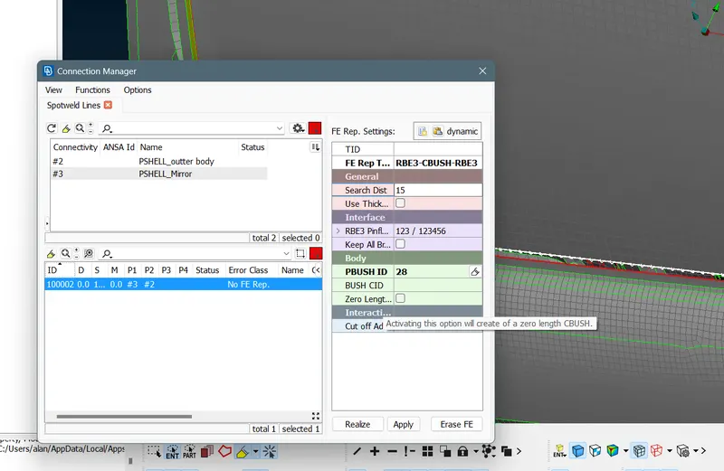
- Go the connection manager and we have to select on the created spot line to open the dialogue box.
- We have to provide the Spacing value as 10 . It is the distance betweeen bushes created on the part.
- Assign the PID’s(P1,P2) select the mirror and the part to connect.
- select Fe representation - Rbe3-CBush-Rbe3
- We have to provide the Search distance as pers the two distance between the parts selected.
- next step is to create property Id for bhush element.
- Say apply and realize it.
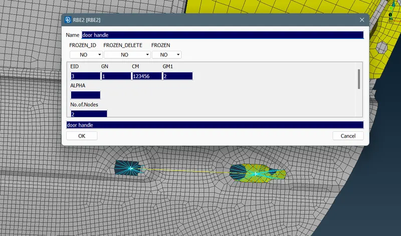
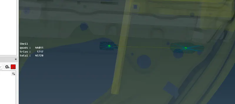
CASE 3: Creating door handle and giving mass.
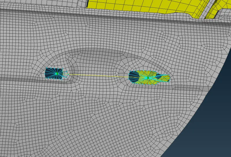
- Create two master nodes for the handle nastran deck>elements>rbe2>many nodes>create master node.
- connect the two master node by rbe2 2 noded elements .
- to assign the mass on the door handle go to nastran deck>elements>conmi>select the two nodes of the handle and give mass value respectively.
CASE 4: Creating bolt and hinge connections on the part.
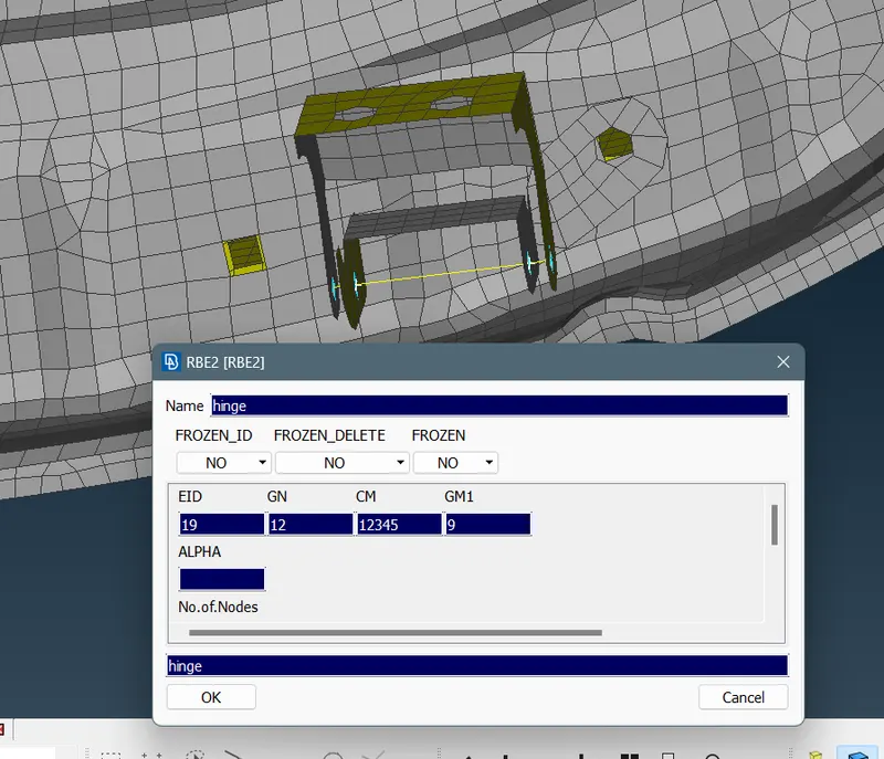
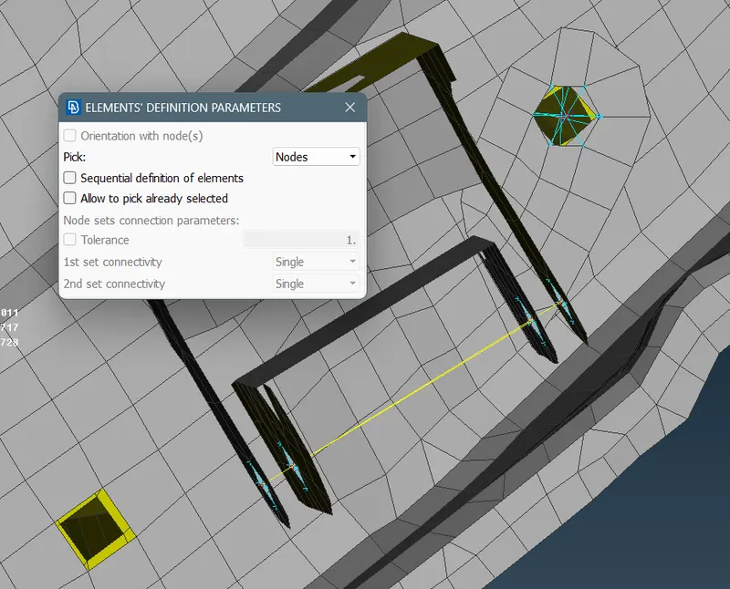
- Create master node and connect with rbe2 elements .
- The difference is for bolt we give 123456 degree of freedon whereas for hinge we neglect one rorational degree of freedom so we give 12345 at dialogue box.
CASE5 : Creating spot weld and seam weld .
- Create a 3d point berween a quad element . Select the quad in an enclosed manner to get the point at the centre.
- Convert the 3D point to spot weld point.
- Go to the connection manager and we have to select on the point.
- We have to select the PID’s(P1,P2) assign the parts to be connected.
- Fe representation - Rbe3-Hexa-Rbe3
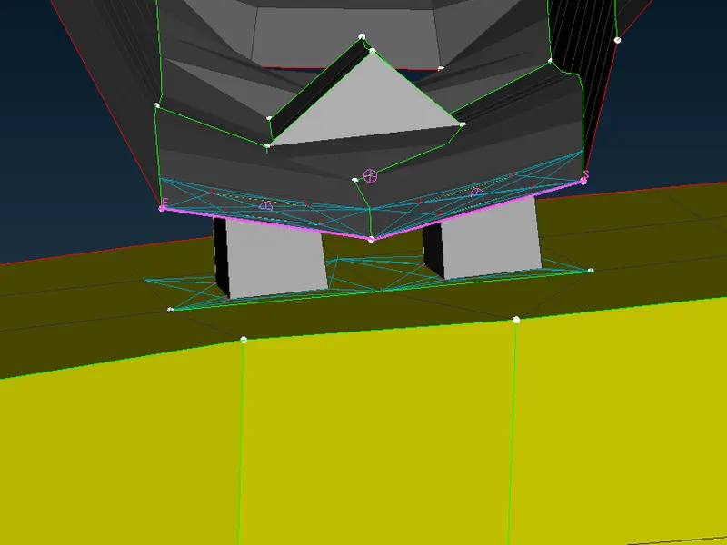
- We have to provide the Search distance base on the two selected parts.
- Create the weld pid before clicking on apply.
- Realize it.
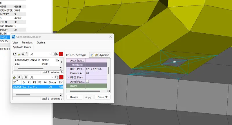
- We can observe hexa elemnt connecting two parts.
FOR CREATING SEAM WELD ,
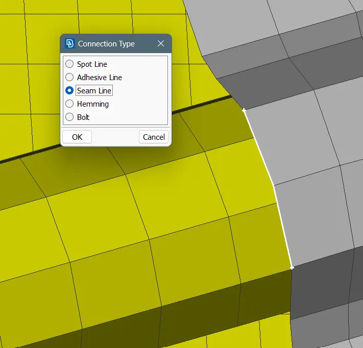
- Create a curve by using the feature2 curve Mesh>Perimeters>Feat2Curve option and convert the curve line into seam line
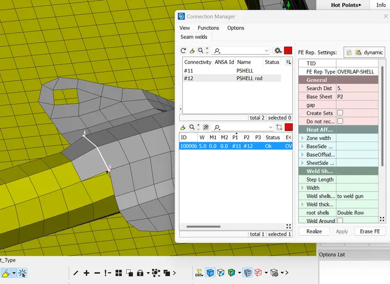
- Go to the connection manager and we have to select it.
- We have to select the PID’s(P1,P2) for the parts we connecting.
- Fe representation - Overlap Shell (For Parallel Surfaces) or Y-joint Shell ( For Perpendicular Surfaces)
- We have to provide the Search distance based on distance between the parts.
- We have to choose the Proper base sheet on which the weld is going will be done
- We have to provide the width value as the target element size. here the value is 5
- Create weld property.
- Say apply and realize it.
CONCLUSION:
Thus different PIDS are created and required connections in done on the given FE Element model
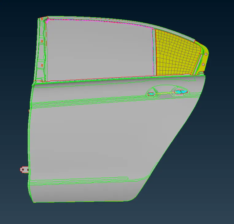
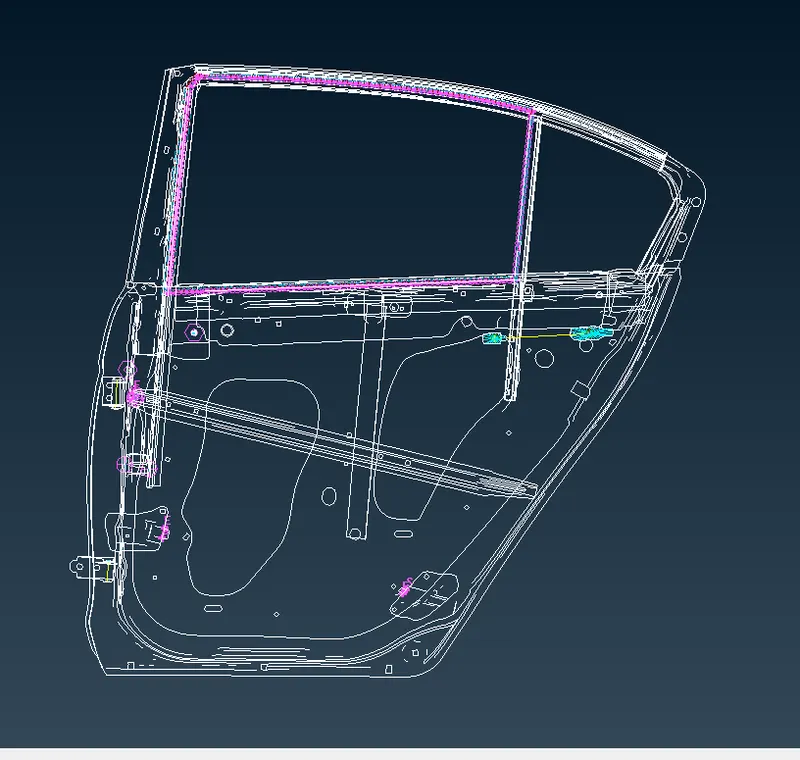
FINAL FE MODEL :
LEARNING OUTCOMES:
- Learned about necesssary connections on the model on ansa software.
- how to connect and choose the different type of connections on different geometric shapes .