Project 2
AIM
Route the Wiring harness on Given car body and Prepare flatten view drawing in CATIA V5. Application of all Packaging rules, Industry best practices studied in this course shall be demonstrated in design. Apply Protection coverings as required.
Given car back door cad data
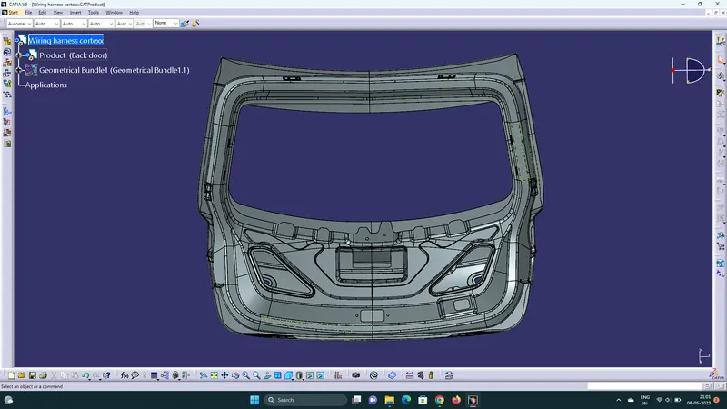
Fig.1.car back door cad file
The above figure shows the given back door cad data .Here routing the wiring harness for the following electrical components attached to the back door .
- Tail lamp on both left and right side
- licence plate lamp
- wiper motor on back door
- rear veiw camera
- Interconnection connector to connect back door wiring harness system to vehicle harness system.
here considering this electrical components on back door to route the harness.Harness mounting and routing management required to provide proper packaging of the wiring harness.it also deals with clearance management and manufacturability .
components used to route the wiring harness
Download the 3d data of required connectors and mountings from the site www.te.com
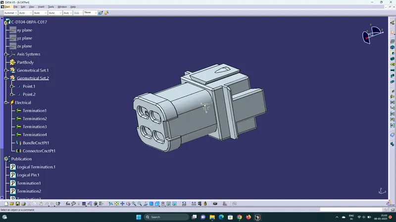
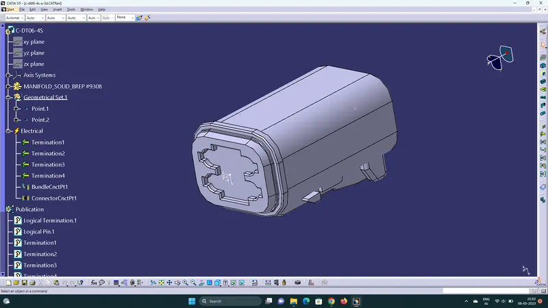
- define the connectors electrically by defining all its properties shown in the below fig.
 .
.
open the cad data of connectors in catia part design workbench and create the connector connection point,connector connection axis system , bundle connection point .Then Switch to electrical part design workbench and define it as a connector also define connector connection point and bundle connection point.
Fir tree clip
First define geometrical parameters such as entry point, entry plane, exit point, exit plane and base plane .Then switch to electrical part design workbench and define the fir-tree clip as support using support command and define the parameters.
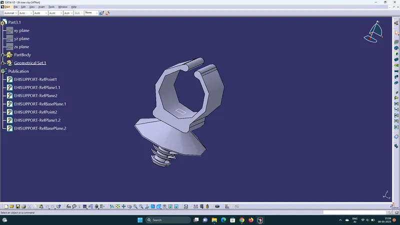
Next create a new product in assembly workbench named as back door harness contex assembly.it is the top level product file inside this product file created geometrical bundle and wire harness electrical bundle.Given back door cad data added inside this contex assembly.
Geometrical bundle contains all of the harness components i.e connectors ,clip, gromets and actual physical bundle segments and branches.All the components should be defined electrically .
- Add all the electrically defined components to the geometrical bundle.place the components at proper location for routing the harness
- Then switch into the electrical harness assembly workbench and Geometrical bundle product file should be electrically defined using the Define Geometrical bundle option .
design criteria followed to route the wiring harness
- Wiring harness routed by considering the factors ease in manufacturing, accessibility, easy removal and easy maintenance of attached equipments and routing harness.
- Wiring harness should be routed in such a way that it is easy to assemble on a vehicle.
- Wiring harness should be kept away from sharp environments like sheet metal brackets, panel edges, corners etc.
- Avoid harness routing and clipping in blind zone of operator during harness installation.
- Ensure that routing meets the clearance requirements with the different surrounding parts.
- Routing shall provide enough slack for each branch to avoid additional stress on wire and terminal crimping joints but ensure that extra slack does not cause wiring harness foul with surrounding parts and impact desired clearance requirements.
- Enough clips should be provided to ensure the positive clearance with surrounding and safety of wiring harness.
- Branch length should be minimum 50mm.
- Minimum distance between clip and nearest branching point should be 25mm.
- Minimum distance between two breakouts should be 50mm.
- Limit the no. of branches from single branch point upto 4.
- Ensure that harness protection is provided according to surrounding temperature, manufacturabilty and expected reliability.
- The min. bend radius ratio is to be 1.4.
Harness routing and packaging
- The connectors placed at proper location by using the manipulation tool.here we have two connectors for tail lamp , two connectors for licence plate lamp, one for wiper motor and one for rear view camera .In this concept routing connectors placed tentatively.
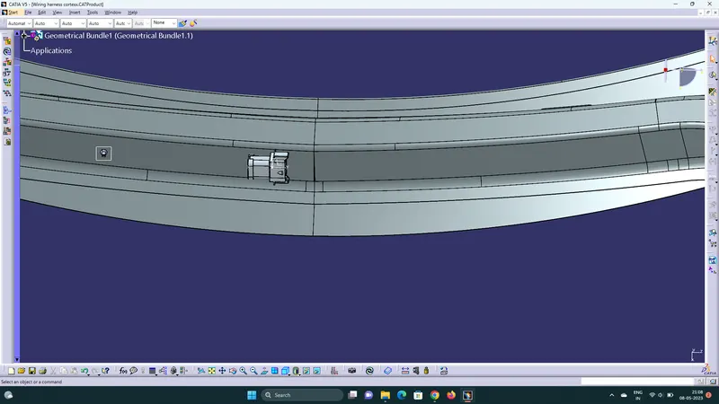
- Here we have one interconnection connector to connect engine harness system to vehicle harness system.so it required additional parking provision haness .
Adding supporting components fir-tree clip . provide positive clamping and ensure proper clearance management for the wiring harness routing and also help to prevent the harness fouling on mechanical components.
- Fir Tree can be placed at appropriate location and ensure clearance management.
- After finalization of the routing, request the sheet metal design team to provide the holes for fix the Fir tree clips as per their location.
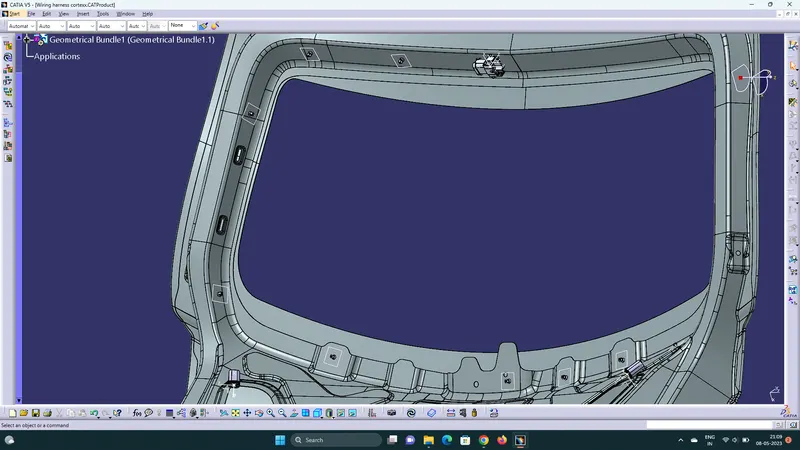
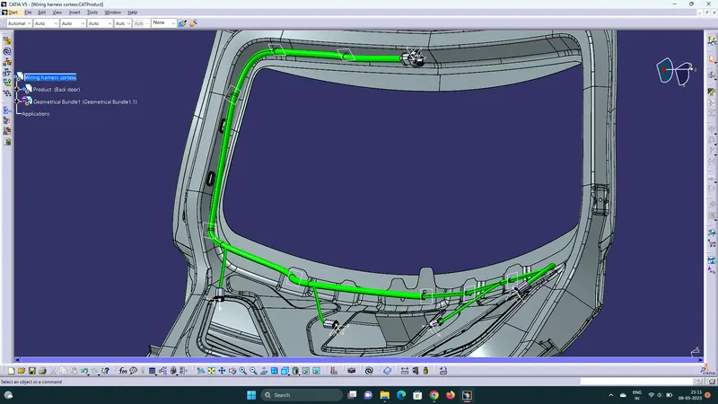
After define the geometrical bundlel electrically, Then select the multibranchable command to start the bundle routing and click on the route definition.
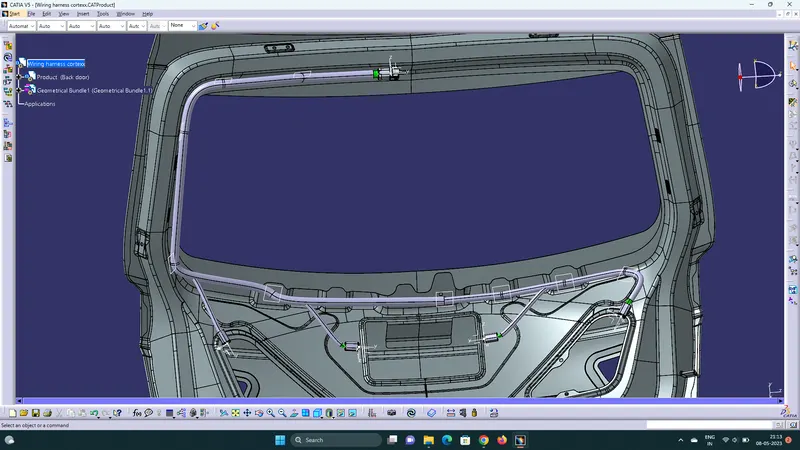
The bundle routing starts from interconnection connector to the fir tree clips and finally route the tail lamp connector. Adding branche points to route the wiring harness from main branch to various connectors.
Proper bend radius and slack provided for the bundle segment to avoid stress on the wire.
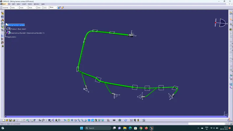
- Add protective coverings on the wiring harness to protect wiring . protective covering created by using define protection part command in the electrical part design workbench. Select part , and define the parameters as per the requirement.
- The created corrugated tube can be added into the catalog by store device command and selecting the catalog file created for protective covering. then appropriate protective covering added to the bundle segments.
WIRING HARNESS FLATTENING
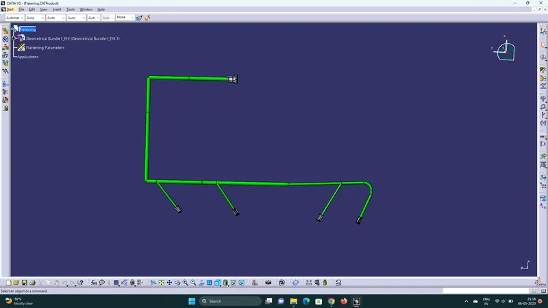
Create a new product file for flatten the wiring harness and save as in the same folder where the wiring harness contex assembly is saved. Then switch to Electrical harness flattening workbench and select harness flattening parameters and define harness flattening parameters. Before creating flatten view, Make sure that selecting 'Double line' for bundle segment and 'Double' line for protective covering.
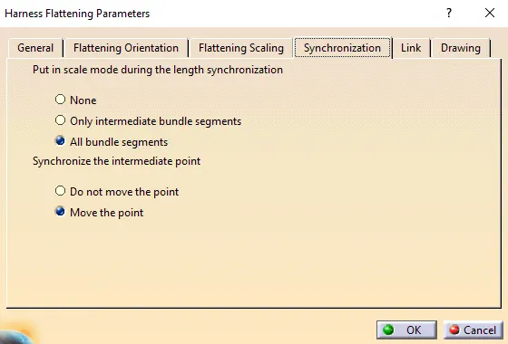
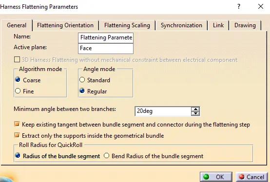
fig.18.flattening parameters
After setting the parameters Extract the geometric bundle from the wiring harness context product file.Then go to flatten option.Select the plane and all branches to flatten the wiring harness .
use manipulators (rotate.roll etc) to arrange the bundles in proper location