Week 11 - Final project
AIM
- To create a door interior part from the inputs of class A surface along with master section by following the design rules followed in tier 1 and OEM industries in catia v5.
OBJECTIVES
- Create a sketch by using Positioned sketch
- All the should be sketches should be Iso-Constrained
- Ensured Proper Tree Structure
- Geometrical sets should having a proper name based on the sketches present inside of it
- Create thickened part using master section for reference
- Create the mounting features as per design guidelines in the industry and with master sections
- Creating of Draft analysis & Tooling analysis
- Creation of parting lines and check tooling feasibility
-
Find a attachment strategy for the door panel complete work.
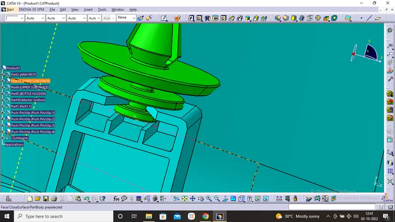
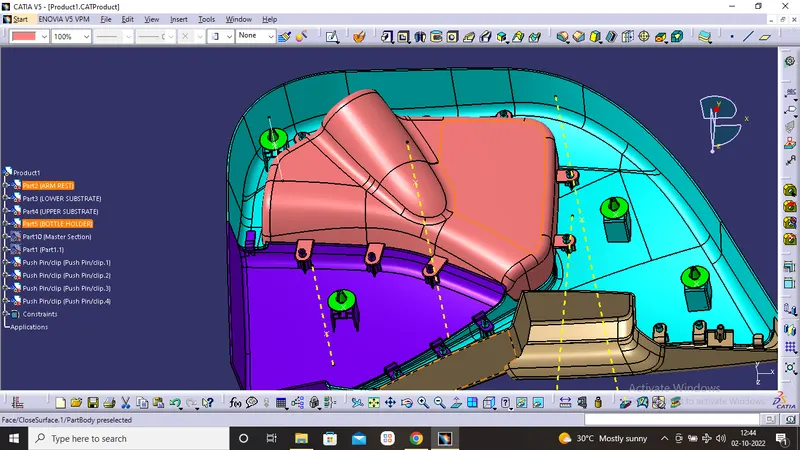
Use Push pin with Dog house for Lower substrate – Door panel attachment
Use heat stakes for part to part attachment
Given Input
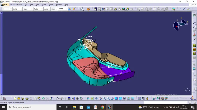
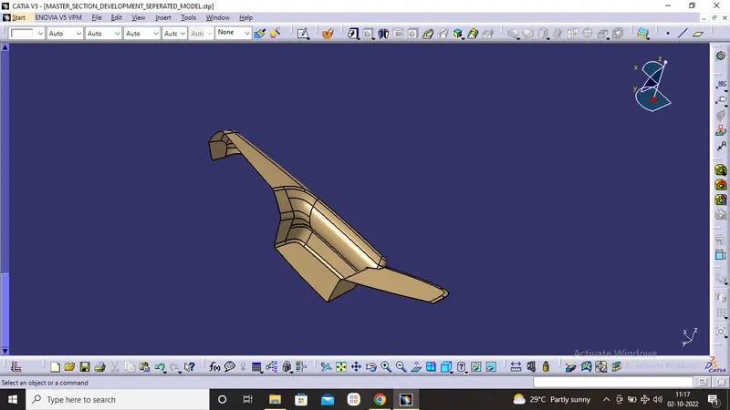
ARM REST
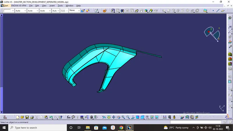
LOWER SUBSTRATE
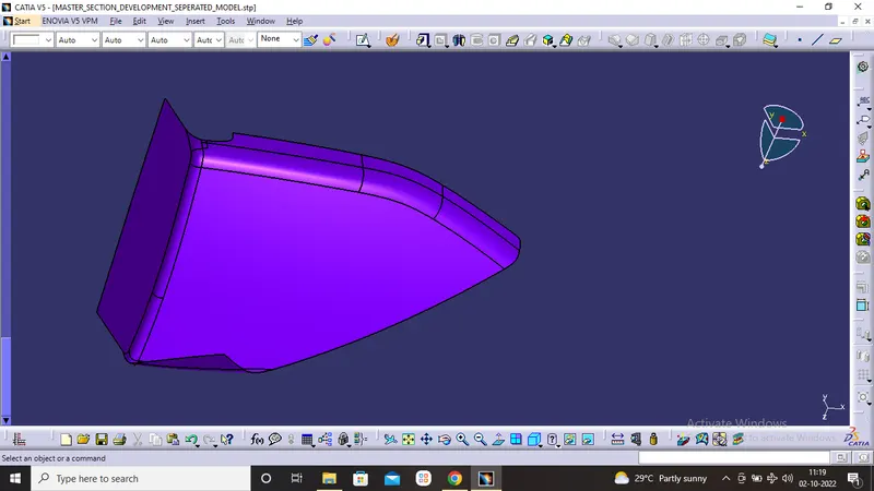
UPPER SUBSTRATE
BOTTOL HOLDER
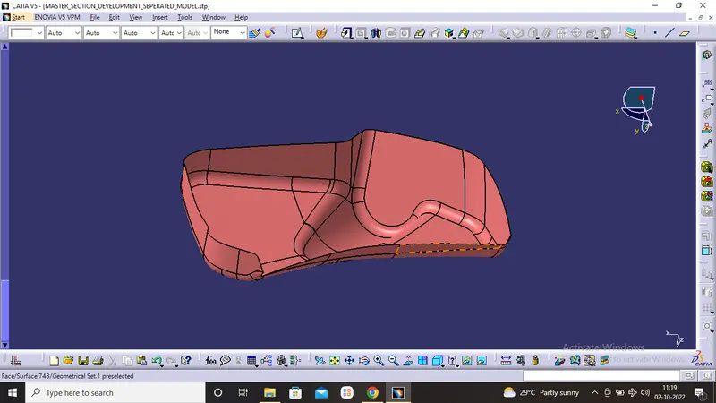
SURFACE MODELING for ARM REST
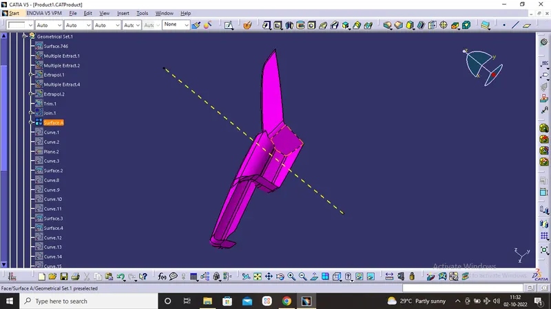
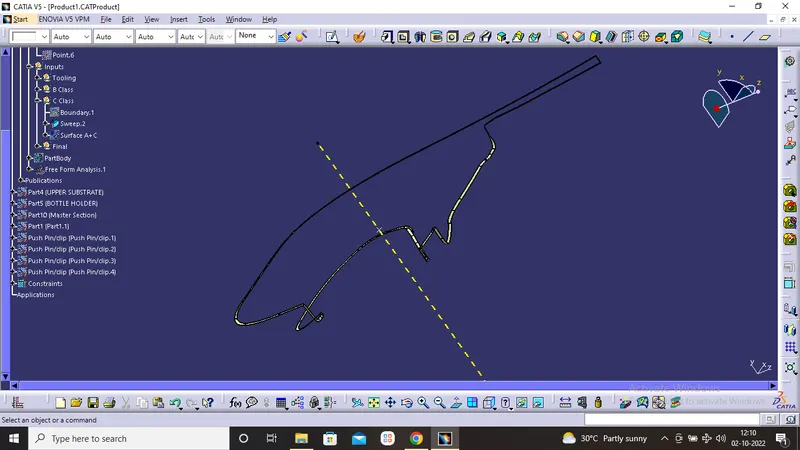
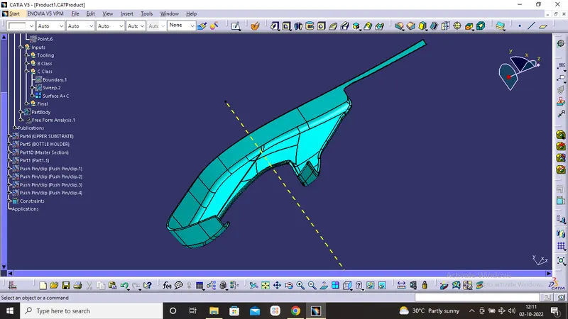
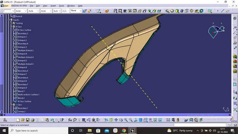
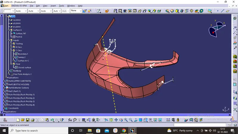
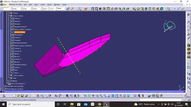
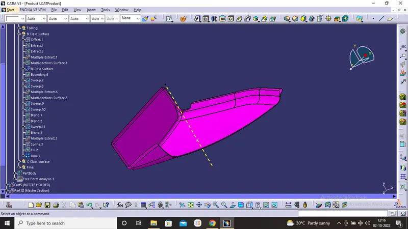
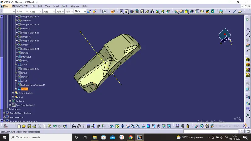
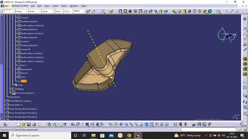
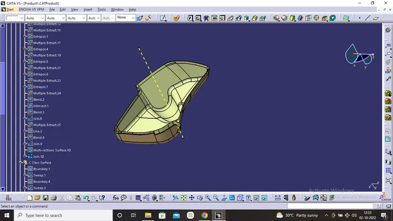
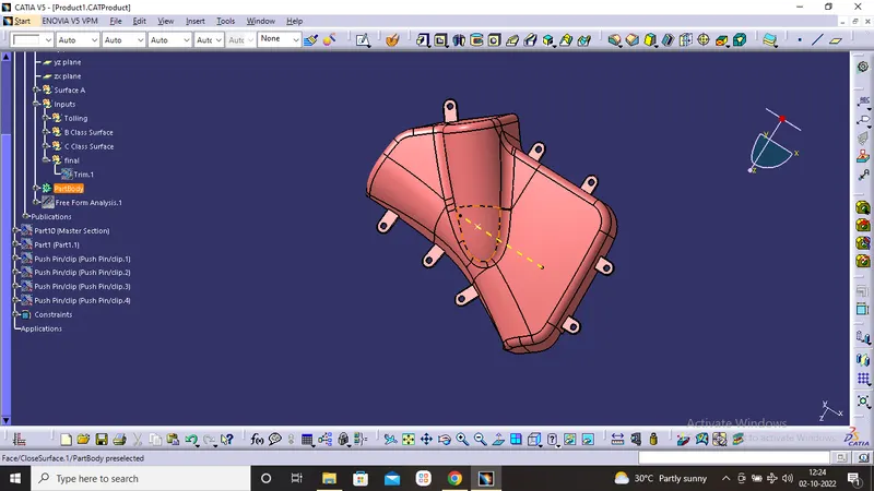
- Class B surface has been created by offsetting the surface 2.5mm. Surface that are not offsetting were formed by using multi section command and join them.
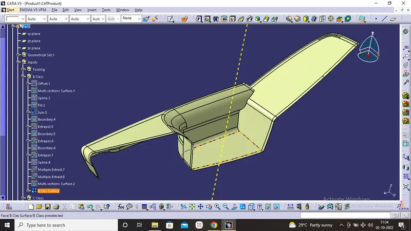
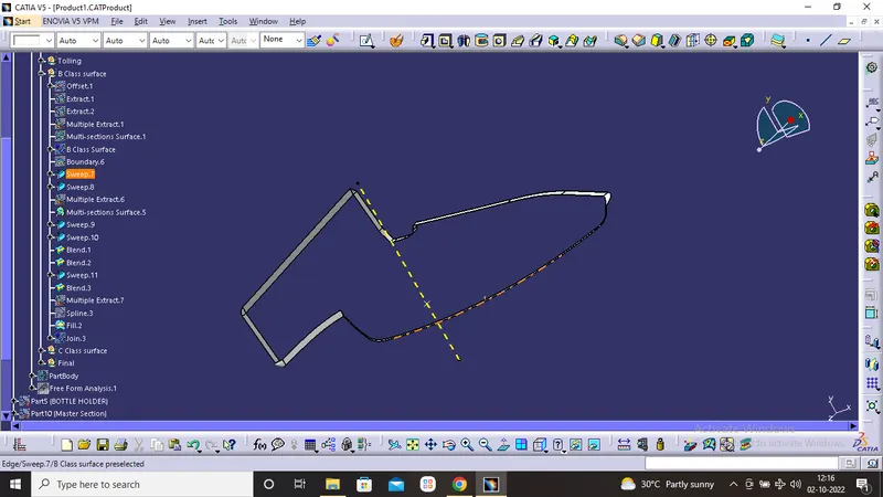
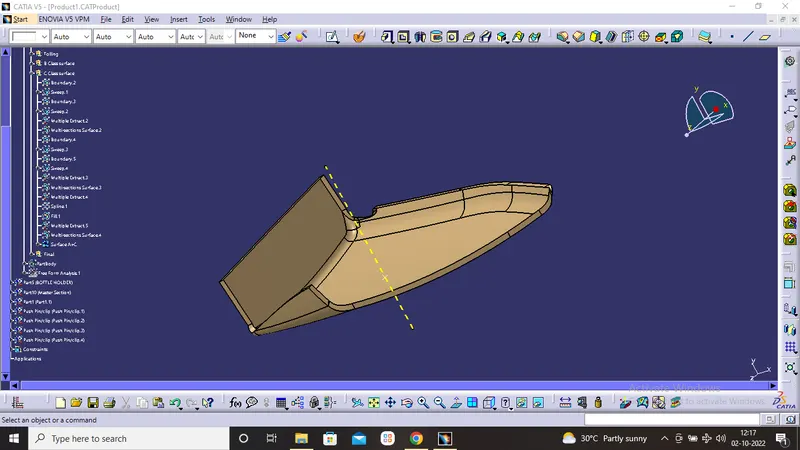
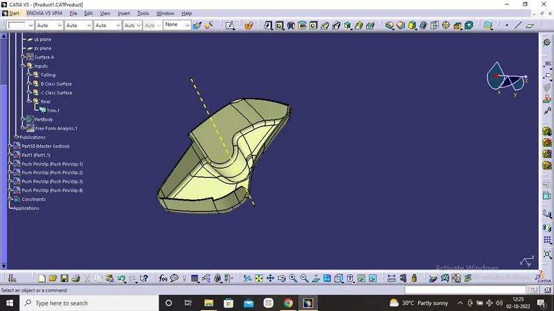
- Using the multiple extract commands boundaries of class, A surface were extracted. Class C surface joins class A and Class B surfaces. It is created using the sweep command. Inputs for the sweep were extracted boundary, class a surface angle values and length of the sweep. Due to surface irregularities, it was not possible to make a single sweep. Hence several sweep and multi section were created, and finally they joined together to create a Class C surface.
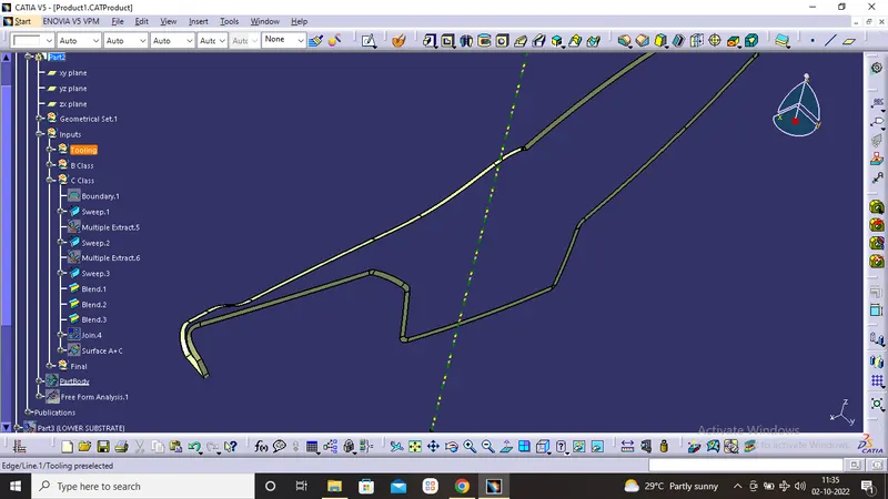
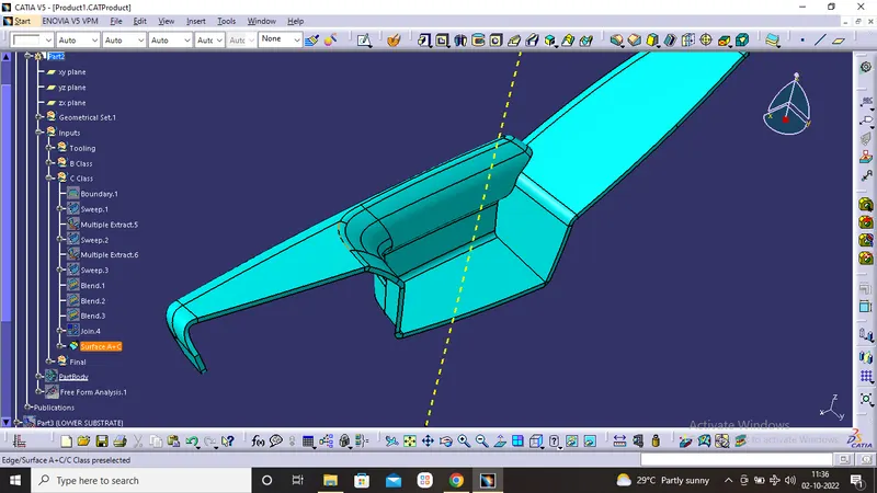
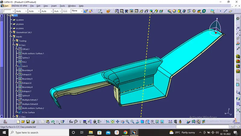
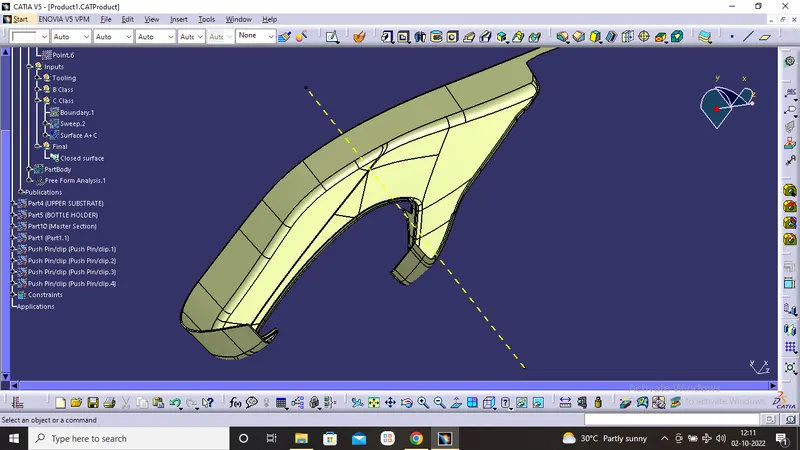
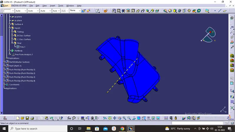
- After joining the class, A and class C together, the join surface trimmed with class B surface to create a close surface. Some errors showing that’s why we extrapolate the class B surface for correctly trim the class A and C with class C.Go to part workbench insert a body and doing close surface operation create the solid body.
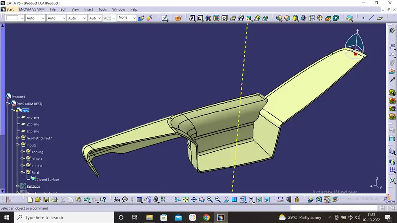
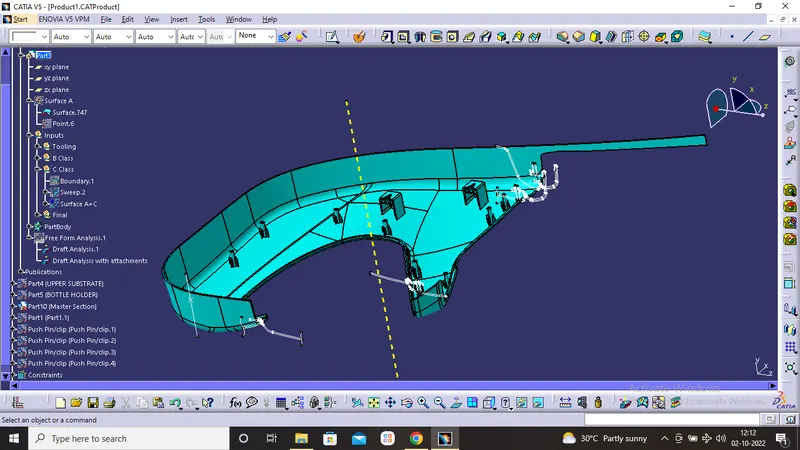
- As given Master section in dialog box. Flanges, dog house, heat stack are created are using Master section.
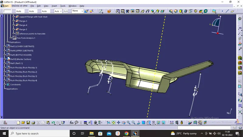
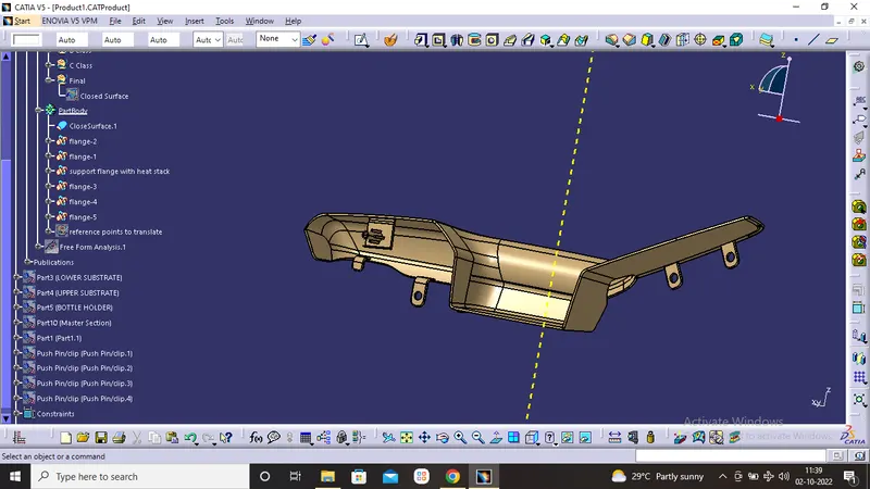
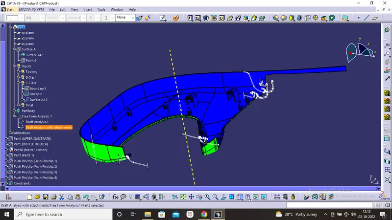
- Draft Analysis are performed afer attachments are added as per Master section.
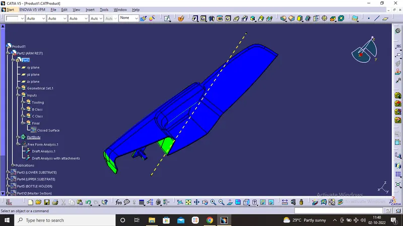
SURFACE MODELING for LOWER SUBSTRATE.
- Same steps followed As like DOOR ARM REST
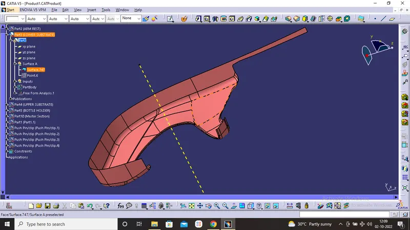
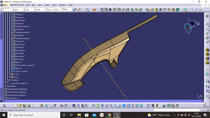
SURFACE MODELING for UPPER SUBSTRATE.
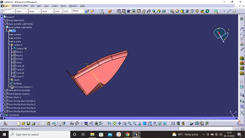
- Same steps followed As like DOOR ARM REST
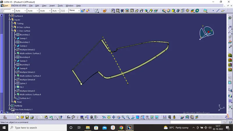
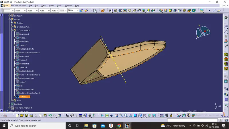
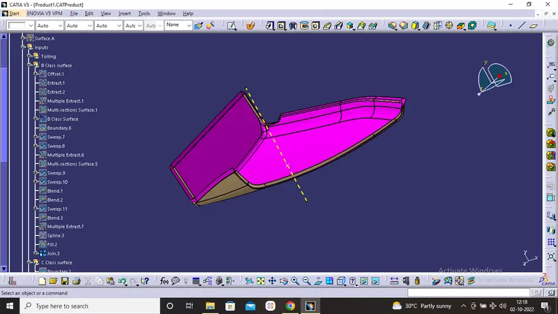
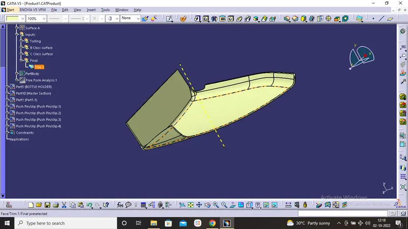
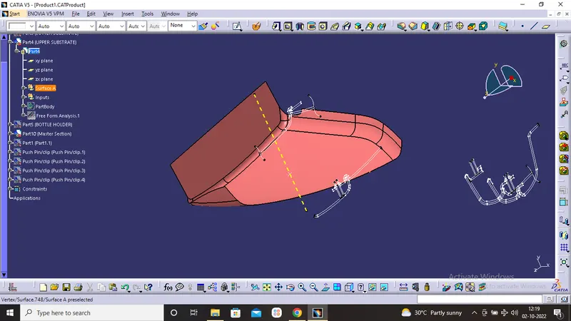
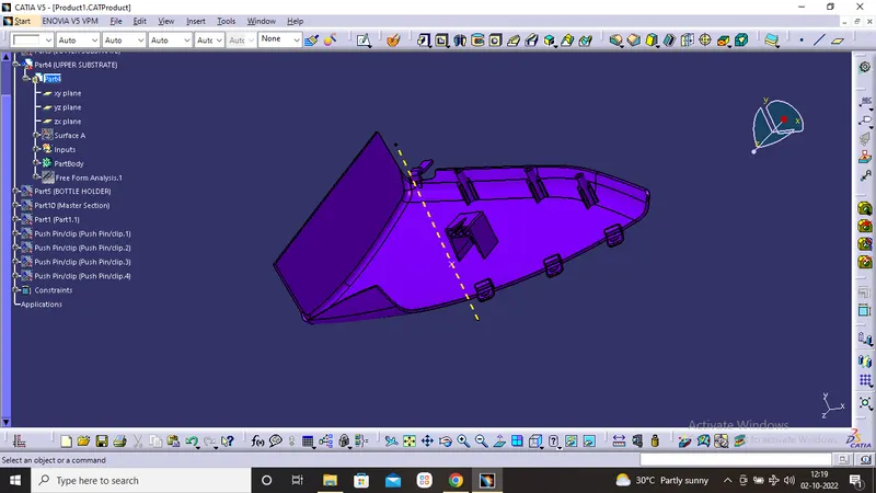
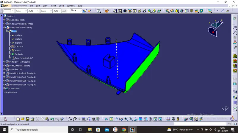
SURFACE MODELING for BOTTLE HOLDER.
- Same steps followed As like DOOR ARM REST
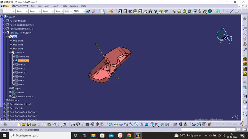
DOG HOUSE
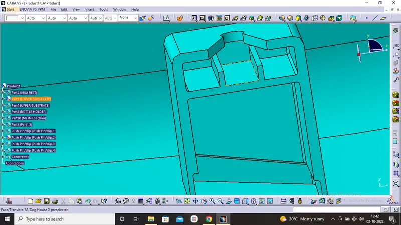
- Dog house is the attachment feature which helps you to assemble things at certain heights and also resolve the plastic defects.
- There are plenty dog house design which can be used for assembly purpose but we will be using the one provided to ous by the resources.
- The master section or the enginnering drawing must be followed for creating the dog house.
PUSH PINS
- These pins are used for the assembly purpose .
- These pins are guided into the sheet metal body.
- The pin is assembled over the dog house on one side and other into sheet metal.
CONCLUSION
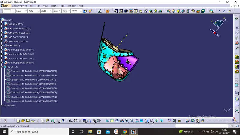
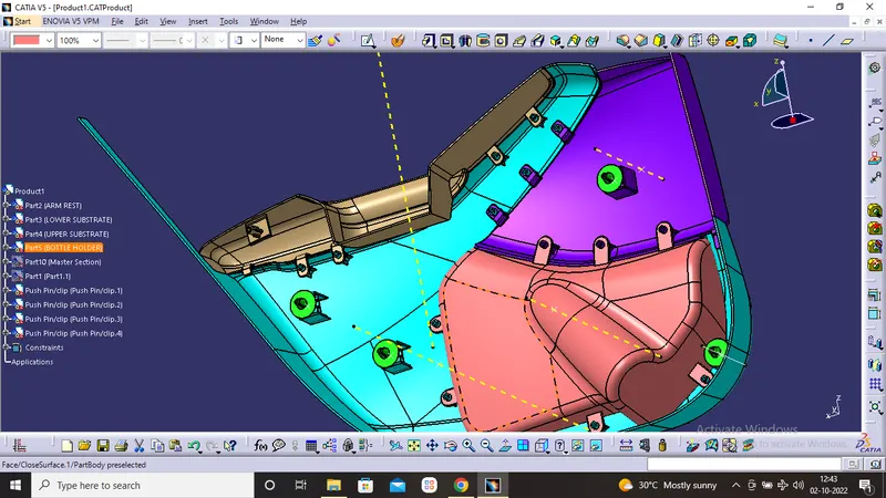
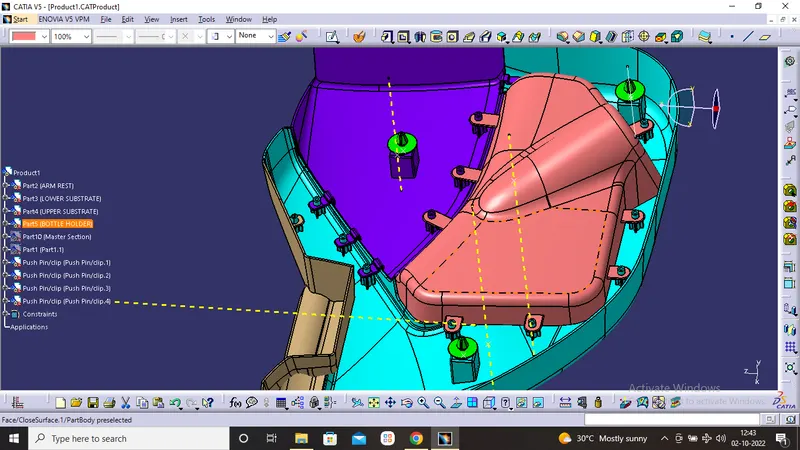
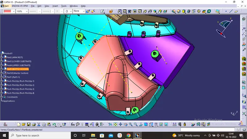
- The door panel successfully designed by following all design rules used in automotive industry. All the attachment feature are properly placed at different location.
THANK YOU.