Design of backdoor
AIM:
To design the back door of the carr and make the inner panel for the back door and also design the necessary re-enforcements.
Introduction:
An automobile back door or Tailgate is the panel that covers the boot (or trunk) of an automobile. It enables access to the main luggage compartment. A hinge allows the boot lid to be raised, while devices such as springs or gas cylinders hold it up in the open position The Backdoor is an assembly of many parts such as inner panel, outer panel upper, outer panel lower and Reinforcement. Inner panel is attached to the outer panel using mastic sealant.
Total no. of parts in Backdoor are:
- Back door outer panel (upper)
- Back door outer panel (lower)
- Back door inner panel
- Hinge reinforcements
- Gas stay reinforcements
- Latch and striker reinforcements
- Wiper motor reinforcements
Design Considerations for a Back Door-
- Rear Visibility for Functionality and Safety.
- Boot Space and Accessibility.
- Type of Backdoor Opening (For individual vehicle requirement).
- Rear Crash regulations.
Procedure:
Firstly we have to check if there are any surface irregularities in the skin data, If irregularies are there, then repair if by using a bridge curve and Through curve mesh and sew it.
Then we create a sealing flange. Generally with the help of master sketch, we will design the panel with appropriate dimensions. But here there is no master sketch,we designed by assumption.
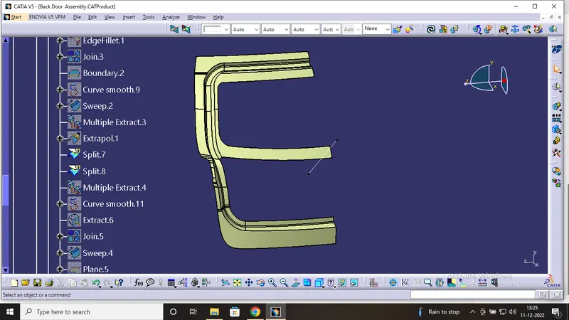
Here the sealing flange is created by maintaining a gap between inner panel to the sealing flange.
Tooling Direction-
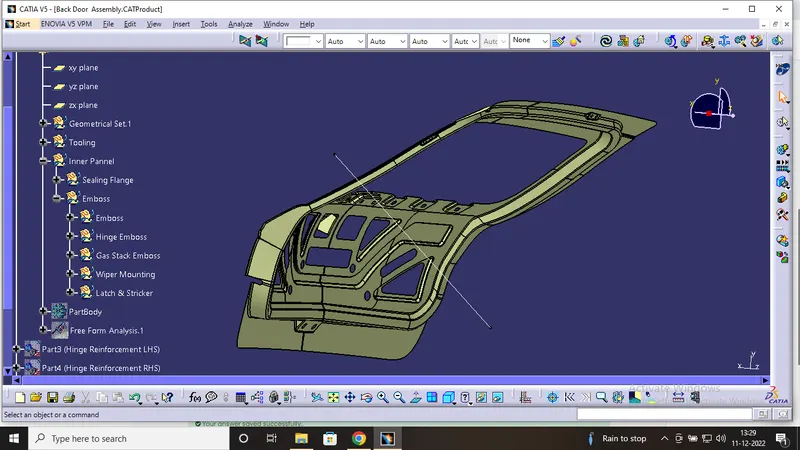
The back door is going to be manufactured by deep drawing process. In Deep Drawing process have a tool which is core and Die. The core part follows the single Straight path the inclination angle of the core is known as a tooling direction. The tooling direction/axis is created so, that the Manufacturing team take the reference of this tooling axis and manufacture the part accordingly.
Inner Panel:
Force Distribution:
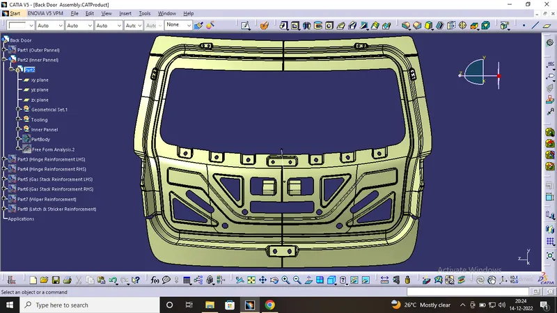
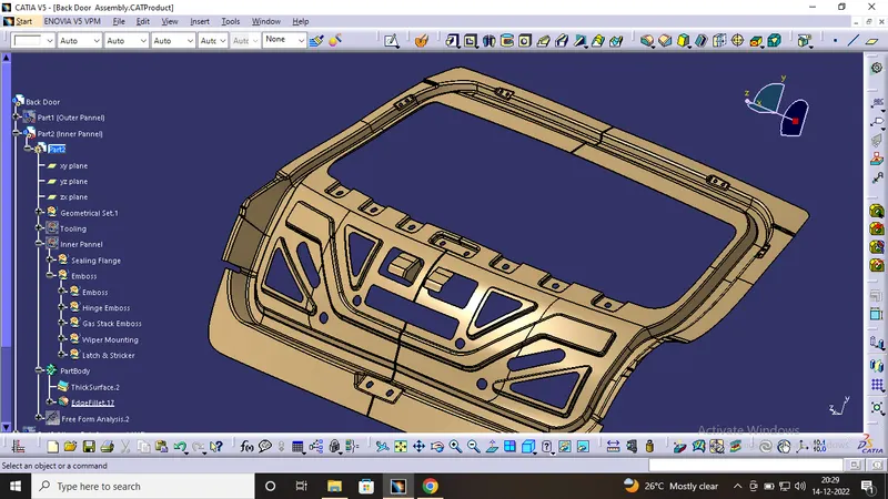
When the crash occurs o the car at rear end, the impact force should dissipate to outside. For this we created the embosses in the combination of U/V, undercuts, mastics.
Mastic region:
- The mastic points are defined on the backdoor inner panel where the backdoorcan easily deform. They help the backdoor outer panel to come back to its original shape after it gets deformed.Mastic sealants are elastic compound that behaves like the rubber.
- The gap between the inner panel and the outer panel over the embosses is filled with mastic sealents at certained specified places, this helps to reducing vibrations and overall NVH ( Noise, Vibration, Harshness).
- Then, the sheet will bend with the help of another die to make the flange in "L" shape.
- Thus, the flange will have somehow same design and the length will completely depend on the Cut-out, if we need more length of flange, then we need to cut more sheet.
Emboses:
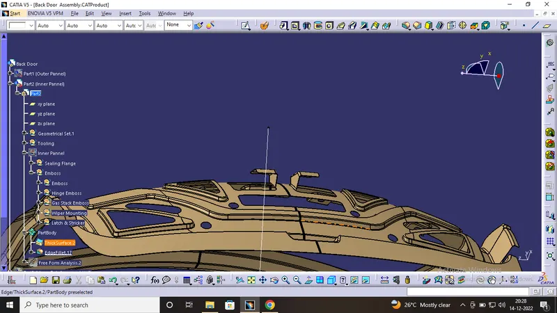
- With the distinctive cross-section, embosses are created. The embosses are used to increase the strength of the backdoor. While designing we should keep in mind that it should not be over strength. So we prefer to design big embosses rather than small embosses. These embosses are used to disipate the forces sideways.
Hinge Emboses
The backdoor is a swinging commodity, which swings with the help of hinges. This can be done by tentatively positioning the hinges and on the hinge axis, we take a center point. again we take another center point(approx) on the latch hole. Taking these two points as a reference we draw a circle. This circle is the striker trajectory and it has to be perpendicular. This can be achieved by moving the hinge axis back and forth or by rotating the latch area.
To create hinge mounting emboss
- A plane was taken because mounting area should be flat or should not have any radius of curvature.
- A sketch was drawn on that plane.
- The emboss command was used to make the hinge emboss feature by using plane as an end cap of hinge emboss.
- And holes were created for the nut and bolts for assembly of hinge.
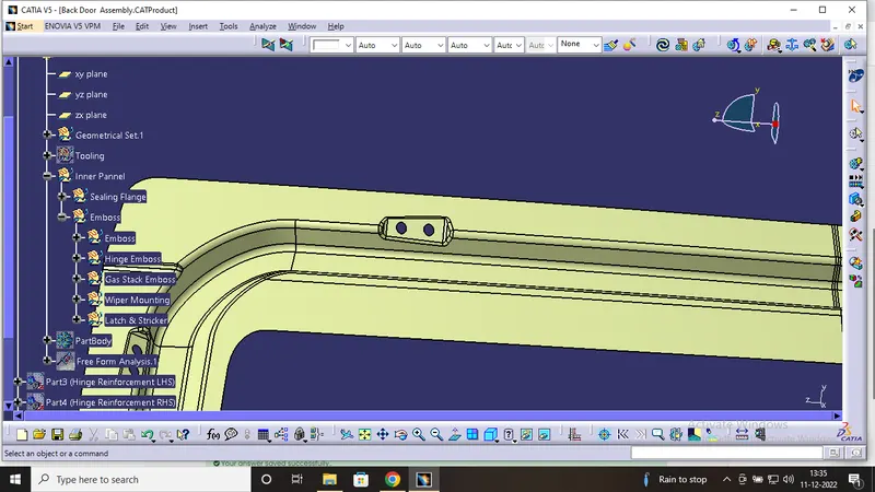
Gas Stay Embose:
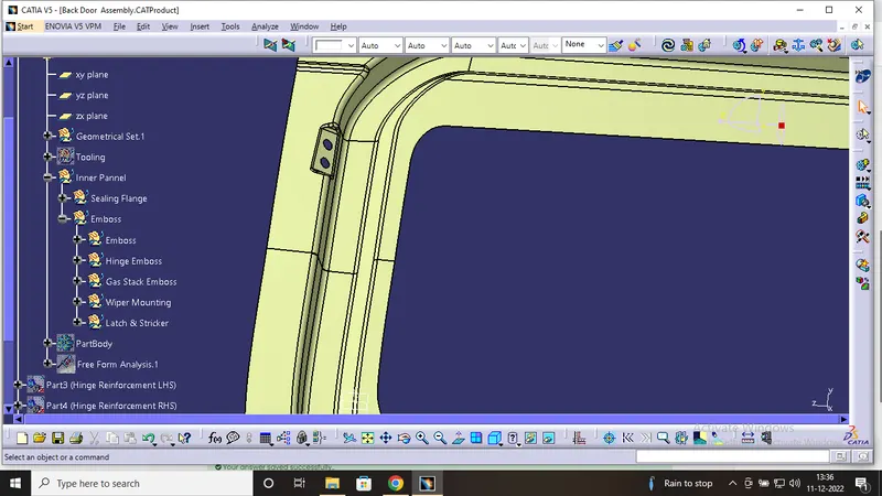
Wiper Embose:
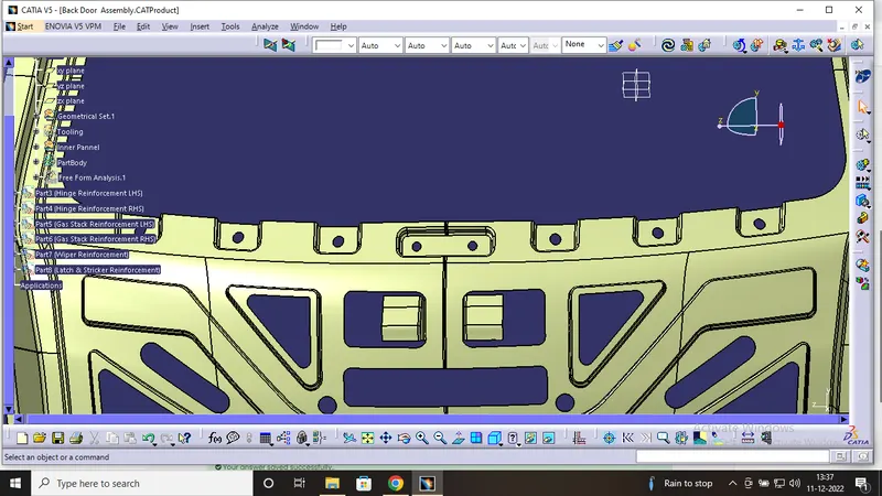
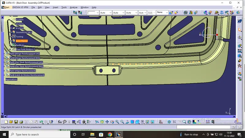
Latch and Striker Trajectory:
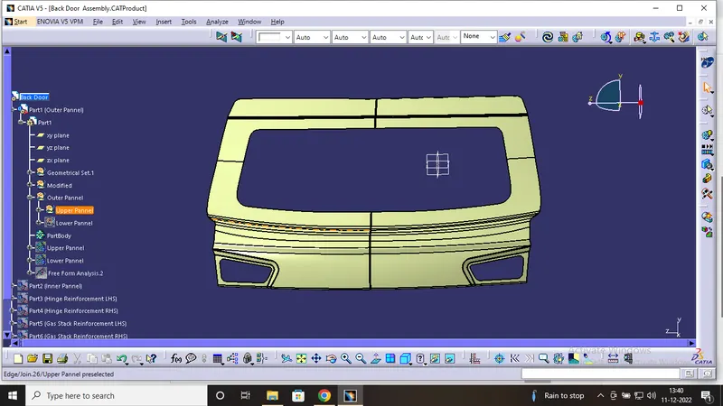
Outer Upper Panel:
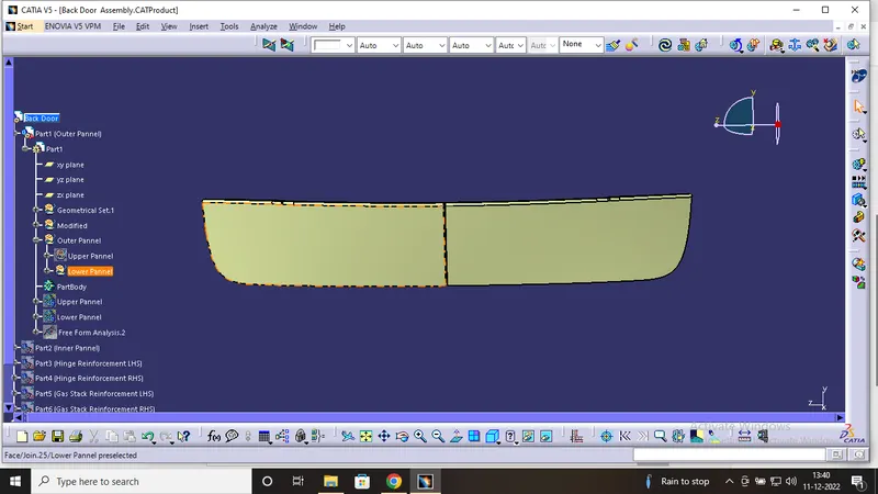
Outer Lower Panel:
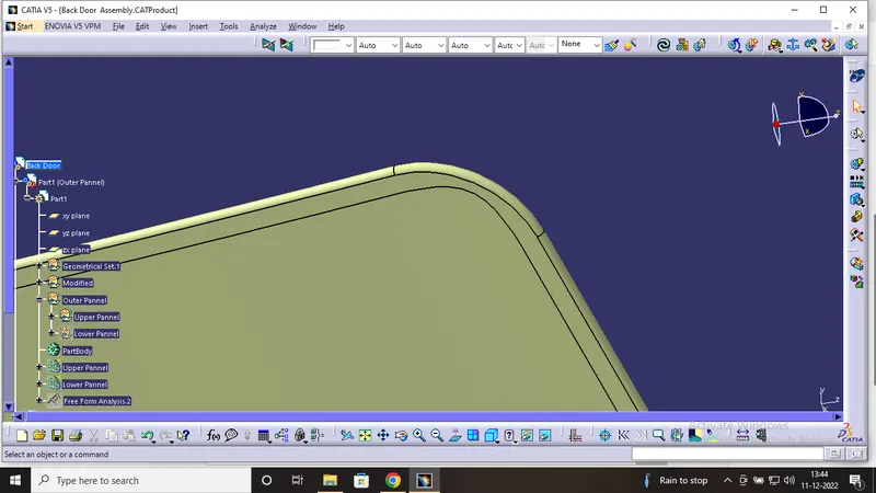
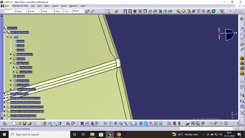
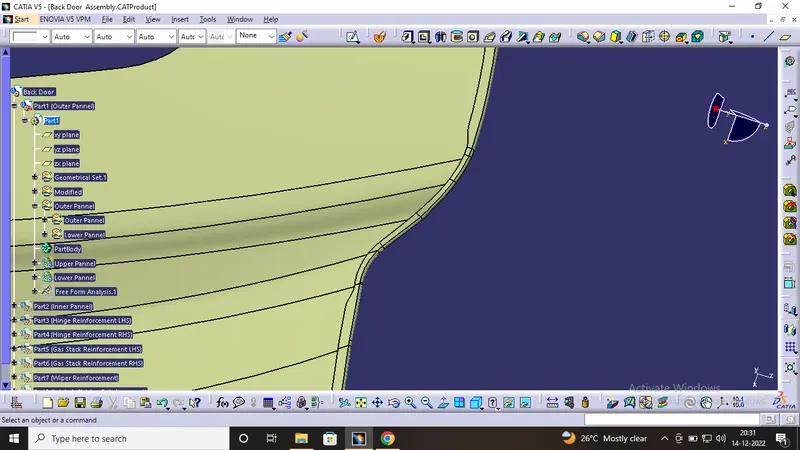
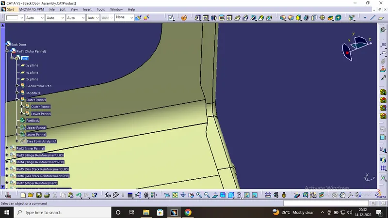
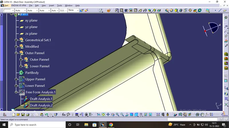
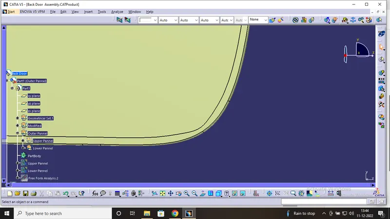
What is hem ?
Hems are folds to the edge of a part to create a rounded, safe edge. Hems may be open, flat, or tear-dropped, and tolerances depend on the hem’s radius, material thickness, and features near the hem. The process of creating hems is called hemming.
Hems are created by bending a flange of your part back on itself. This increases the strength of the hemmed edge and also gets id of any sharp edges.
Reinforcements:
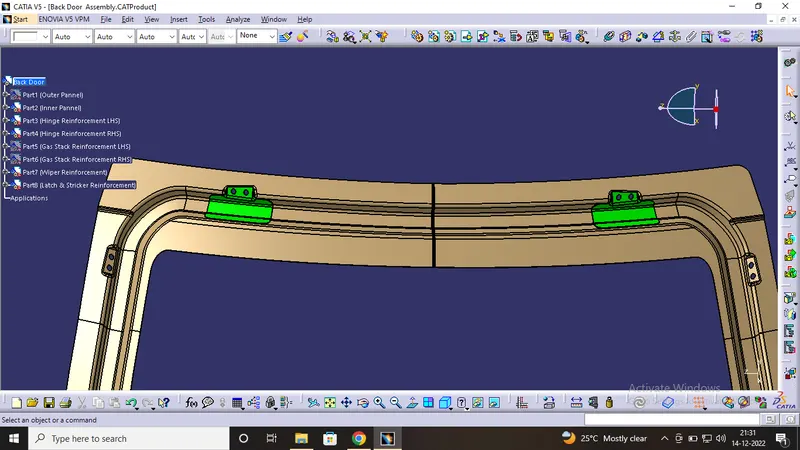
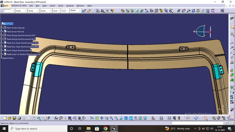
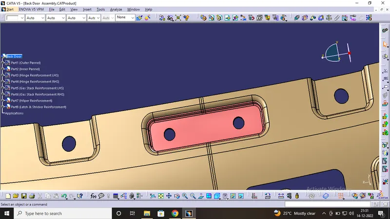
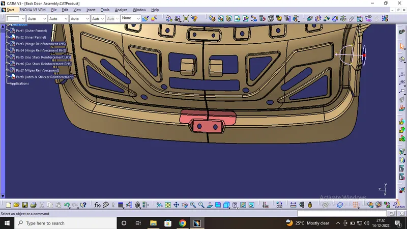
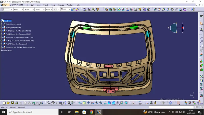
Reinforcements are generally used to increase the strength of the mountings so that there is no unnecessary dents or noise occurs at the time of motion. This not only add strength to the part but also increase the overall stiffness of the part so that the part is completely stable. The Reinforcements used are
1) Latch and Stricket Reinforcement
2) Wiper Motor Reinforcement
3) Hinge Reinforcement
4) Gas Stay Reinforcements
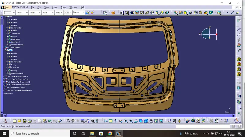
The Following Image shows the reinforcement that are used on different areas of the inner panel. They are usually spot welded on the inner panel.
Draft Analysis:
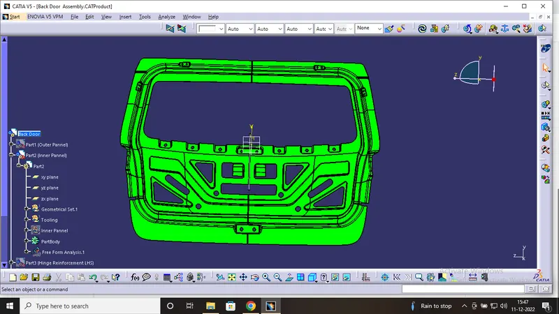
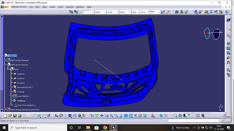
Draft Analysis is done to analyze the draft angle. This allows us to verify whether the product will be easily removed from the tool.
When designing a product it needs to be slightly angled so that the tool can be pulled away from the part easily, without deformation or damage. This slight angle is called draft.
- In the 1st tooling direction, all components are made
- In the 2nd tooling direction, the parts whic shows negative draft , we will increase the tooling angle to avoid neative draft.
Inner Pannel
Outer Panne
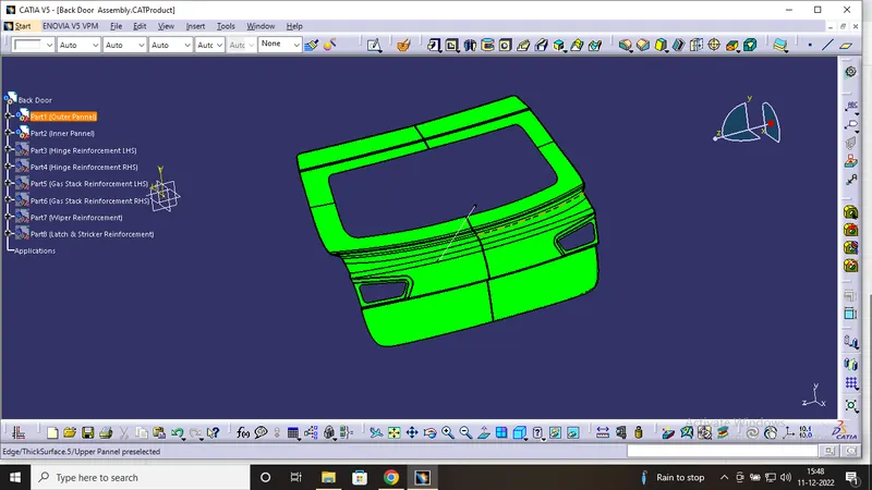
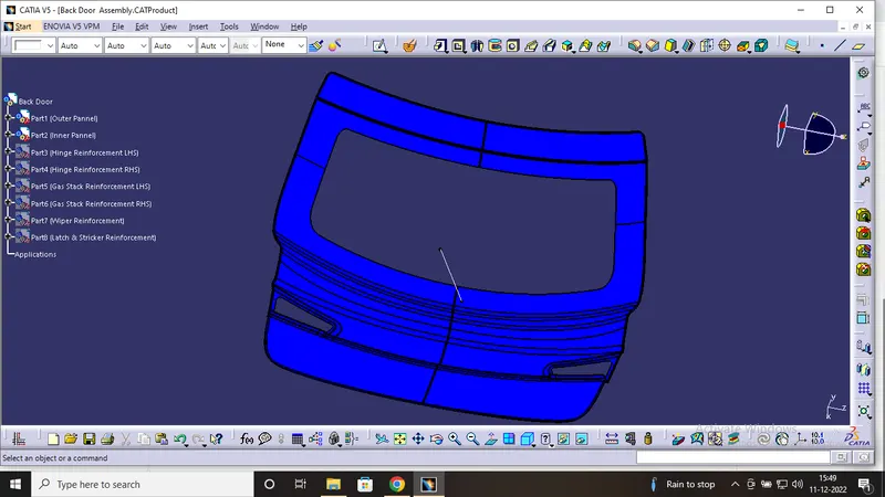
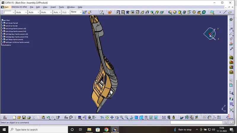
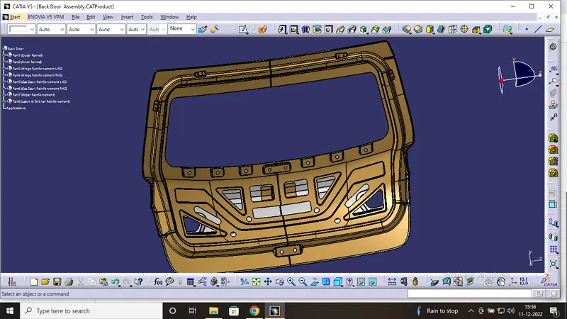
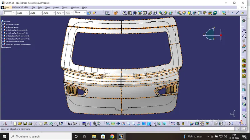
Back Door Assembly:
Thus the top down approach is followed to design the back door assembly. At first from the given styling surface the inner panel was created by Offseting the outrer Panel and then individual parts were designed accordingly by using the Inner panel Surfaces. The Reinforcement and other commodities were designed by using the inner surface as the reference thus following the top down approach. The following image show the assembly model of the Back Door.