Project-1: Powertrain for aircraft in runways
Part A
1,
MOTW = Maximum take-off weight
MLW = Maximum landing weight
MRW = Maximum ramp weight
MZFW = Maximum zero-fuel weight
MEW = Manufacturer's empty weight
OEW = Operational Empty weight
The aircraft gross weight is the total aircraft weight at any moment during the flight or ground operation. The aircraft gross weight will vary during the consumption of fuel and refuelling time also varies during the droping and carrying of payload.
The maximum takeoff weight (MTOW) or maximum gross takeoff weight (MGTOW) or maximum takeoff mass (MTOM) of an aircraft is the maximum weight at which the pilot is allowed to attempt to take off, due to structural or other limits. The analogous term for rockets is gross lift-off mass, or GLOW. MTOW is usually specified in units of kilograms or pounds. MTOW is the heaviest weight at which the aircraft has been shown to meet all the airworthiness (airworthiness is the measure of an aircraft's suitability for safe flight) requirements applicable to it. MTOW of an aircraft is fixed and does not vary with altitude, air temperature, or the length of the runway to be used for takeoff or landing. Maximum permissible takeoff weight or "regulated takeoff weight", varies according to flap setting, altitude, air temperature, length of runway and other factors. It is different from one takeoff to the next, but can never be higher than the MTOW.
The maximum landing weight (MLW) is the maximum aircraft gross weight due to design or operational limitations at which an aircraft is permitted to land. The MLW is set in order to ensure safe landings; if an aircraft weighs too heavy during touchdown, it may suffer structural damage or even break apart upon landing. The maximum take-off weight is almost always higher than the maximum landing weight, so that an aircraft can weigh less upon landing due to burning fuel during the flight.
The maximum ramp weight (MRW) (also known as the maximum taxi weight (MTW)) is the maximum weight authorised for manoeuvring (taxiing or towing) an aircraft on the ground as limited by aircraft strength and airworthiness requirements. It includes the weight of taxi and run-up fuel for the engines and the auxillary power unit (APU).It is greater than the maximum takeoff weight due to the fuel that will be burned during the taxi and run-up operations. The difference between the maximum taxi/ramp weight and the maximum take-off weight (maximum taxi fuel allowance) depends on the size of the aircraft, the number of engines, APU operation, and engines/APU fuel consumption, and is typically assumed for 10 to 15 minutes allowance of taxi and run-up operations.
The maximum zero-fuel weight (MZFW) of an aircraft is the total weight of the airplane and all its contents, minus the total weight of the usable fuel on board. Unusable fuel is included in MZFW. For example, if an aircraft is flying at a weight of 5,000 kg and the weight of fuel on board is 500 kg, the ZFW is 4,500 kg. Some time later, after 100 kg of fuel has been used, the total weight of the airplane is 4,900 kg, the weight of fuel is 400 kg, and the MZFW is unchanged at 4,500 kg. As a flight progresses and fuel is consumed, the total weight of the airplane reduces, but the MZFW remains constant (unless some part of the load, such as parachutists or stores, is jettisoned in flight). For many types of airplane, the airworthiness limitations include a maximum zero fuel weight.
The manufacturer's empty weight (MEW) (also known as manufacturer's weight empty (MWE)) is the weight of the aircraft "as built" and includes the weight of the structure, power plant, furnishings, installations, systems, and other equipment that are considered an integral part of an aircraft before additional operator items are added for operation. Basic aircraft empty weight is essentially the same and excludes any baggage, passengers, or usable fuel. Some manufacturers define this empty weight as including optional equipment, i.e. GPS units, cargo baskets, or spotlights.
The Operational Empty weight (OEW) is the sum of the ‘as built’ manufactures empty weight (MEW), plus any standard items (SI) plus any operator items (OI), EW = MEW + SI + OI. The EW is calculated for each aircraft series and each unique configuration of an aircraft and is confirmed by periodically weighing it. The Operating empty weight (OEW) is the sum of the empty weight and the crew plus their baggage. Standard items include all structural modification or configuration orders that may have altered the MEW, including all fluids necessary for operation such as engine oil, engine coolant, water, hydraulic fluid and unusable fuel. Operator items include fixed, optional equipment added by the operator for service reasons. The weight added to the aircraft above its OEW for a given flight is variable and includes fuel for the flight and the cargo. Cargo depends upon the type of aircraft; i.e., passengers plus baggage for a transport or commuter airplane, materiel for a cargo airplane, stores for fighters/bombers and service loads such as meals and beverages. Fuel and cargo weights may alter the centre of gravity and flight performance, and require careful calculation before each flight.
2,
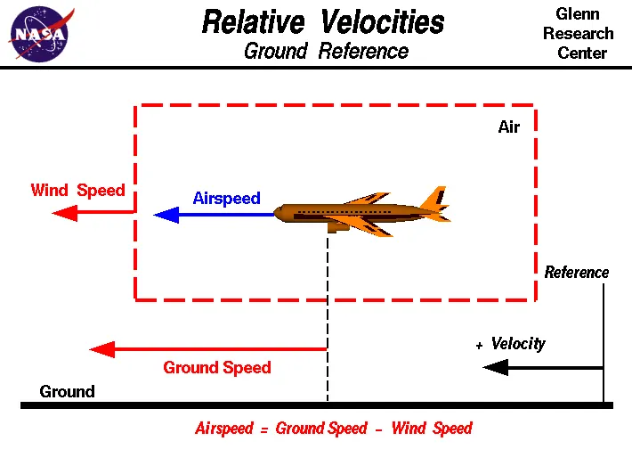
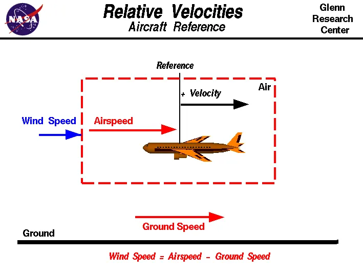
| Ground speed | Air speed |
|
It is the speed of aircraft relative to the surface of earth |
It is the speed relative to the air, it is flying in. |
| It determines that how fast an aircraft will get to the destination. | It determines that wheather enough air flow present around aircraft to make it fly. |
| Ground speed is the sum of air speed and wind speed. | Independent on the ground speed |
- The two relative velocity diagrams of aircraft with respect to air reference and ground reference.
- Wind speed is the vector difference between the ground speed and air speed.
- If wind speed is zero, then ground speed equals to the air speed.
3,
Taxiing is the movement of an aircraft on the ground, under its own power, in contrast to towing or pushback where the aircraft is moved by a tug. The aircraft usually moves on wheels, but the term also includes aircraft with skis or floats (for water-based travel).
An airplane uses taxiways to taxi from one place on an airport to another; for example, when moving from a hanger to the runway. The term "taxiing" is not used for the accelerating run along a runway prior to takeoff, or the decelerating run immediately after landing, which are called the takeoff roll and landing rollout, respectively.
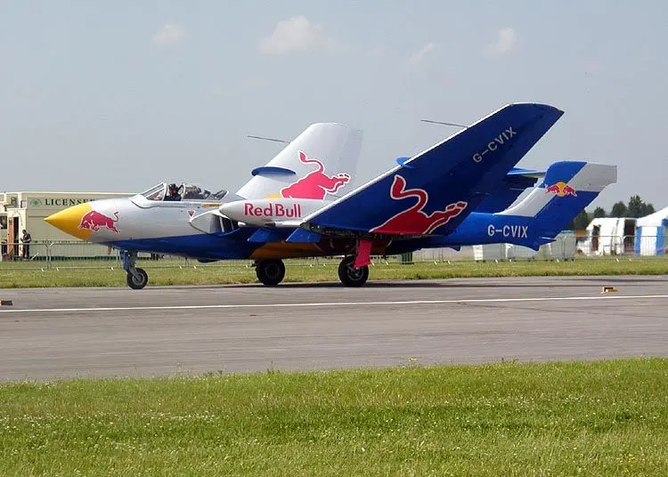
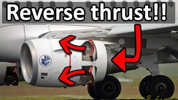
The reason why the aircraft is not using the engine power to move on the ground is that, although many aircrafts are capable of moving in backward using reverse thrust, as result the jet blast or prop wash might cause damage to the terminal building or equipment. Engine close to ground may also blow sand and debris forward and then suck them into the engine, causing damage to the engine.
4,
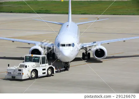
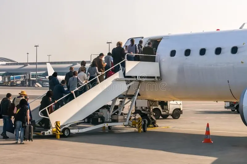
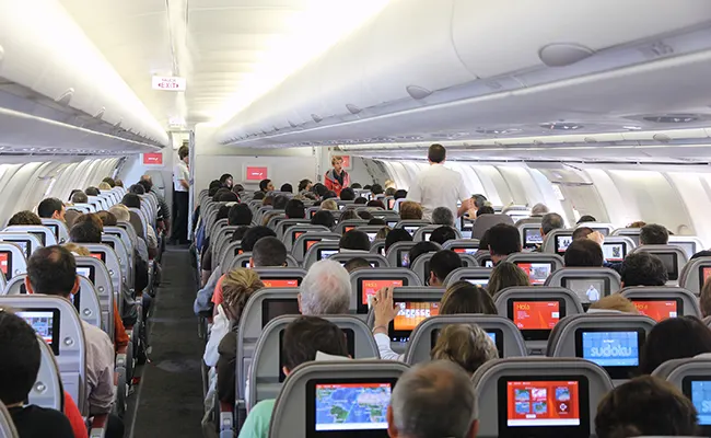
After all the passengers , crews and luggages are loaded in the plane, the door is closed and the pilot informs air-traffic control that the flight is ready for departure. The apron handler removes the chocks. A so-called pushback truck reverses the aircraft into taxiing position, pushing it with a towbar attached to the nose-wheel strut. Or, in the most modern versions, by actually lifting the wheel. That speeds up coupling and decoupling. The process is called towing. The aircraft taxis to the runway to depart at the agreed time.
Pushbacks at busy aerodromes are usually subject to ground control clearance to facilitate ground movement on taxiways. Once clearance is obtained, the pilot will communicate with the tractor driver (or a ground handler walking alongside the aircraft in some cases) to start the pushback. To communicate, a headset may be connected near the nose gear. Since the pilots cannot see what is behind the aircraft, steering is done by the pushback tractor driver and not by the pilots. Depending on the aircraft type and airline procedure, a bypass pin may be temporarily installed into the nose gear to disconnect it from the aircraft's normal steering mechanism.
Once the pushback is completed, the towbar is disconnected, and any bypass pin removed. The ground handler will show the bypass pin to the pilots to make it clear that it has been removed. The pushback is then complete, and the aircraft can taxi forward under its own power.
5,
Take off:
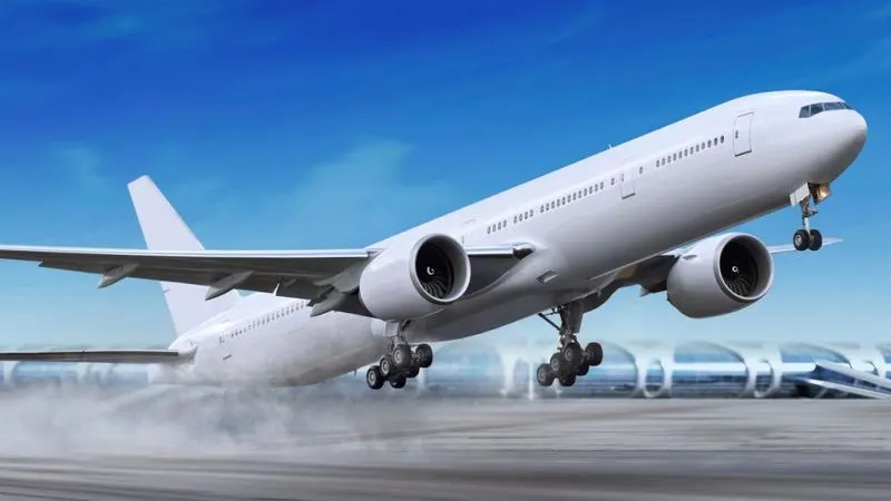
Takeoff is the phase of flight in which an aerospace vehicle leaves the ground and becomes airborne. For aircraft traveling vertically, this is known as liftoff. For aircraft that take off horizontally, this usually involves starting with a transition from moving along the ground on a runway.
An airplane in flight is acted on by four forces: lift, the upward acting force; gravity, the downward acting force; thrust, the forward acting force; and drag, the backward acting force (also called wind resistance). Lift opposes gravity and thrust opposes drag. Drag and gravity are forces that act on anything lifted from the earth and moved through the air. Thrust and lift are artificially created forces used to overcome the forces of nature and enable an airplane to fly. Airplane engine and propeller combination is designed to produce thrust to overcome drag. Their wings are designed to produce lift to overcome gravity.
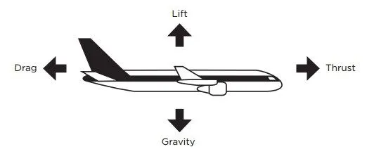
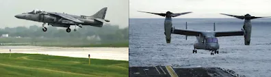
- Thrust—the forward force produced by the powerplant/propeller or rotor. It opposes or overcomes the force of drag. As a general rule, it acts parallel to the longitudinal axis. However, this is not always the case, as explained later.
- Drag—a rearward, retarding force caused by disruption of airflow by the wing, rotor, fuselage, and other protruding objects. As a general rule, drag opposes thrust and acts rearward parallel to the relative wind.
- Lift—is a force that is produced by the dynamic effect of the air acting on the airfoil, and acts perpendicular to the flight path through the center of lift (CL) and perpendicular to the lateral axis. In level flight, lift opposes the downward force of weight.
- Gravity—the combined load of the aircraft itself, the crew, the fuel, and the cargo or baggage. Weight is a force that pulls the aircraft downward because of the force of gravity. It opposes lift and acts vertically downward through the aircraft’s center of gravity (CG).
- Thrust ;
For an aircraft to start moving, thrust must be exerted and be greater than drag. The aircraft continues to move and gain speed until thrust and drag are equal. In order to maintain a constant airspeed, thrust and drag must remain equal, just as lift and weight must be equal to maintain a constant altitude. If in level flight, the engine power is reduced, the thrust is lessened, and the aircraft slows down. As long as the thrust is less than the drag, the aircraft continues to decelerate. To a point, as the aircraft slows down, the drag force will also decrease. The aircraft will continue to slow down until thrust again equals drag at which point the airspeed will stabilize.
Likewise, if the engine power is increased, thrust becomes greater than drag and the airspeed increases. As long as the thrust continues to be greater than the drag, the aircraft continues to accelerate. When drag equals thrust, the aircraft flies at a constant airspeed.
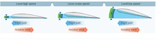
Straight-and-level flight may be sustained at a wide range of speeds. The pilot coordinates AOA and thrust in all speed regimes if the aircraft is to be held in level flight. An important fact related to the principal of lift (for a given airfoil shape) is that lift varies with the AOA and airspeed. Therefore, a large AOA at low airspeeds produces an equal amount of lift at high airspeeds with a low AOA. The speed regimes of flight can be grouped in three categories: lowspeed flight, cruising flight, and high-speed flight.
- Lift ;
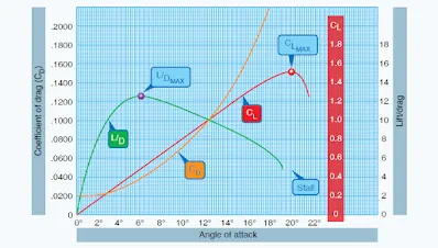
The pilot can control the lift. Any time the control yoke or stick is moved fore or aft, the AOA is changed. As the AOA increases, lift increases (all other factors being equal). When the aircraft reaches the maximum AOA, lift begins to diminish rapidly. This is the stalling AOA, known as CL‑MAX critical AOA. Examine Figure below, noting how the CL increases until the critical AOA is reached, then decreases rapidly with any further increase in the AOA.
Before proceeding further with the topic of lift and how it can be controlled, velocity must be discussed. The shape of the wing or rotor cannot be effective unless it continually keeps “attacking” new air. If an aircraft is to keep flying, the lift-producing airfoil must keep moving. In a helicopter or gyroplane, this is accomplished by the rotation of the rotor blades. For other types of aircraft, such as airplanes, weight shift control, or gliders, air must be moving across the lifting surface. This is accomplished by the forward speed of the aircraft. Lift is proportional to the square of the aircraft’s velocity. For example, an airplane traveling at 200 knots has four times the lift as the same airplane traveling at 100 knots, if the AOA and other factors remain constant.
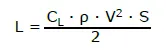
The above lift equation exemplifies this mathematically and supports that doubling of the airspeed will result in four times the lift. As a result, one can see that velocity is an important component to the production of lift, which itself can be affected through varying AOA. When examining the equation, lift (L) is determined through the relationship of the air density (ρ), the airfoil velocity (V), the surface area of the wing (S) and the coefficient of lift (CL) for a given airfoil.
Taking the equation further, one can see an aircraft could not continue to travel in level flight at a constant altitude and maintain the same AOA if the velocity is increased. The lift would increase and the aircraft would climb as a result of the increased lift force or speed up. Therefore, to keep the aircraft straight and level (not accelerating upward) and in a state of equilibrium, as velocity is increased, lift must be kept constant. This is normally accomplished by reducing the AOA by lowering the nose. Conversely, as the aircraft is slowed, the decreasing velocity requires increasing the AOA to maintain lift sufficient to maintain flight. There is, of course, a limit to how far the AOA can be increased, if a stall is to be avoided.
All other factors being constant, for every AOA there is a corresponding airspeed required to maintain altitude in steady, unaccelerated flight (true only if maintaining level flight). Since an airfoil always stalls at the same AOA, if increasing weight, lift must also be increased. The only method of increasing lift is by increasing velocity if the AOA is held constant just short of the “critical,” or stalling, AOA (assuming no flaps or other high lift devices).
Lift and drag also vary directly with the density of the air. Density is affected by several factors: pressure, temperature, and humidity. At an altitude of 18,000 feet, the density of the air has one-half the density of air at sea level. In order to maintain its lift at a higher altitude, an aircraft must fly at a greater true airspeed for any given AOA.
Warm air is less dense than cool air, and moist air is less dense than dry air. Thus, on a hot humid day, an aircraft must be flown at a greater true airspeed for any given AOA than on a cool, dry day. If the density factor is decreased and the total lift must equal the total weight to remain in flight, it follows that one of the other factors must be increased. The factor usually increased is the airspeed or the AOA because these are controlled directly by the pilot.
- Drag;
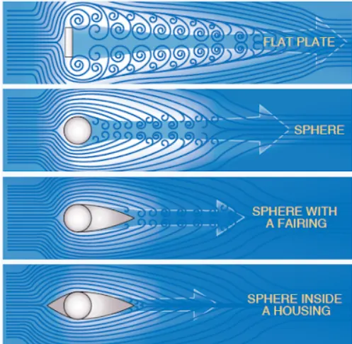
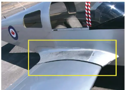
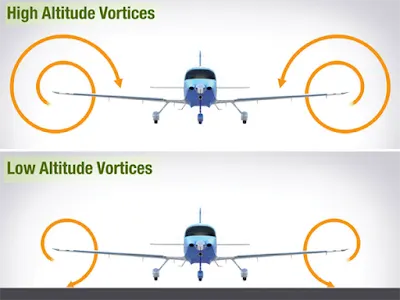
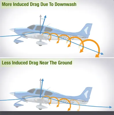
Drag is the force that resists movement of an aircraft through the air. There are two basic types: parasite drag and induced drag. The first is called parasite because it in no way functions to aid flight, while the second, induced drag, is a result of an airfoil developing lift.
Parasite drag ;

- Gravity;
Gravity is the pulling force that tends to draw all bodies to the center of the earth. The CG may be considered as a point at which all the weight of the aircraft is concentrated. If the aircraft were supported at its exact CG, it would balance in any attitude. It will be noted that CG is of major importance in an aircraft, for its position has a great bearing upon stability. The allowable location of the CG is determined by the general design of each particular aircraft. The designers determine how far the center of pressure (CP) will travel. It is important to understand that an aircraft’s weight is concentrated at the CG and the aerodynamic forces of lift occur at the CP. When the CG is forward of the CP, there is a natural tendency for the aircraft to want to pitch nose down. If the CP is forward of the CG, a nose up pitching moment is created. Therefore, designers fix the aft limit of the CG forward of the CP for the corresponding flight speed in order to retain flight equilibrium.
Weight has a definite relationship to lift. This relationship is simple, but important in understanding the aerodynamics of flying. Lift is the upward force on the wing acting perpendicular to the relative wind and perpendicular to the aircraft’s lateral axis. Lift is required to counteract the aircraft’s weight. In stabilized level flight, when the lift force is equal to the weight force, the aircraft is in a state of equilibrium and neither accelerates upward or downward. If lift becomes less than weight, the vertical speed will decrease. When lift is greater than weight, the vertical speed will increase.
Tyre design :-
An aircraft tyre is designed to withstand extremely heavy loads while landing, take off, taxing, and parking. The number of wheels required for aircraft increases with the weight of the aircraft, as the weight of the aeroplane needs to be distributed more evenly. A Boeing 737NG & 737MAX uses 6 wheels, Boeing 787 uses 10 wheels, Boeing 777 uses 14 wheels and Airbus A380 uses 22 wheels. Aircraft tyres work under extreme conditions, carrying up to 340 tons and accelerating at over 250 km/hour at takeoff, in addition to enduring varied environmental stress when in flight and taxiing.
Carcass plies are used to form the tire. They are sometimes called casing plies. An aircraft tyre is constructed for the purpose it serves.
- They support the weight of an aircraft while it is on the ground.
- It also provides the necessary traction for braking and stopping of an aeroplane.
- Tyre also helps to absorb the shock of landing and provide cushioning the roughness of takeoff, roll-out, and taxi operations.
Unlike an automobile or truck tyre, it does not have to carry a load for a long period of continuous operation. However, an aircraft tyre absorbs the high impact loads of landing, and also it’s operating at high speeds for a short time when required.
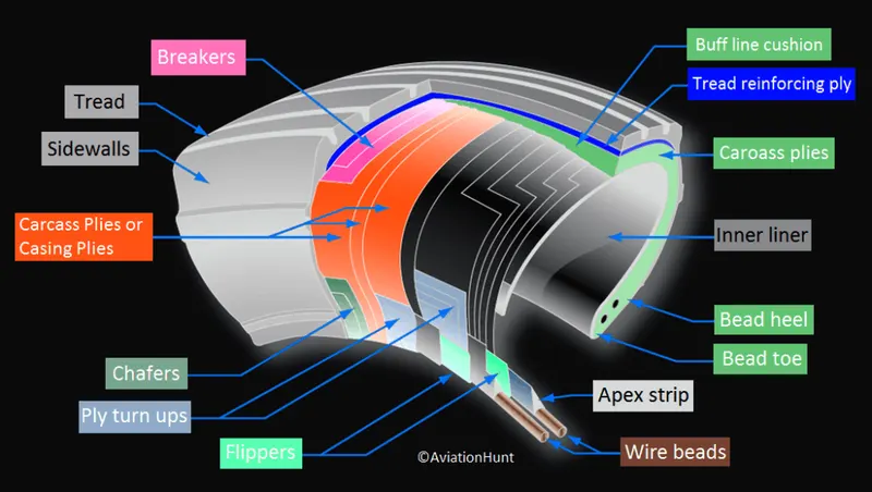
- Retreading – Retreading is methods of restoring a worn tyre by renewing the tread area or by renewing the tread area plus one or both sidewalls. Repairs are included in the tyre retreading process.
- Load Rating – Load rating is the maximum permissible load at a specified inflation pressure.
- Ply Rating – Ply Rating is used to identify the maximum recommended load rating and inflation pressure for a specified tyre. It is an index of tyre strength.
- Speed Rating – The speed rating is the maximum takeoff speed to which the tyre has been tested.
- Skid Depth – Skid depth is the distance between the tread surface and the deepest groove as measured in the mould.
Aircraft tyres must have an approved speed and load rating and have sufficient clearance when retracted through landing gear to allow for tyre growth. Tyre growth is the increase in the size of the tyre due to centrifugal forces at high speed.
- Tubeless tyres are more advantageous over tube-type. There is no longer the use of tube-type tyre in recent aviation. Nowadays all airliners are using tubeless tyres. Tubeless that are meant to be used without a tube has the word TUBELESS on the sidewall of the tyre.
- Almost all airliners are using Radial tyre. Bias is an older design, and it’s mainly used for road vehicles. Radial tyres have the word RADIAL on the sidewall. Radial tires are more expensive than bias-ply tyres. Radial tires are in demand because of their lower life cycle cost and long term value.
Rolling Resistance :-
The friction between aircraft and runway will be proportional to the normal force exerted by the aircraft on the runway.
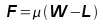
The normal force will be the difference between Weight of aircraft and Lift, the friction coefficient will be typically of a magnitude of 0.02 for a standard tarmac runway.
Tyre Pressure :-
An aircraft tire or tyre is designed to withstand extremely heavy loads for short durations. The number of tires required for aircraft increases with the weight of the aircraft, as the weight of the airplane needs to be distributed more evenly. Two types of tires are used in aircraft applications — bias-ply tires and radial tires. Airliner tires aren't particularly large—the Boeing 737 tires measure 27x7.75 R15, which means they are 27 inches in diameter, 7.75 inches wide, and they are placed on a 15-inch rim. This is much smaller than a semi truck tyre, which can be over 40 inches in diameter and almost 20 inches wide. But plane tires are incredibly strong thanks to cords of nylon, or a synthetic polymer called aramid, that are embedded below the tread.
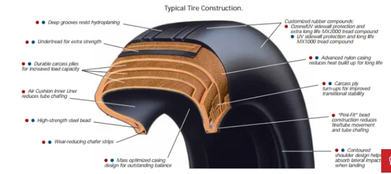
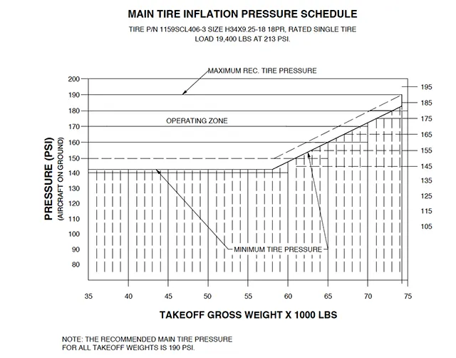
The aircraft tyre never blowout the reason is that aircraft tires are blown up to about 200 psi, or about six times the psi of a car tire. It is the high air pressure that gives airliner tires their strength. Of course, the tire construction needs to be tougher stuff than your average car tire, but the strength of the rubber compounds is primarily to allow such high pressure inflations rather than to resist impact on landing. The nitrogen is the tyre filling gas in aircrafts Helium gas is also used.
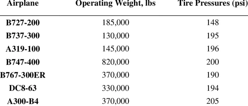
The amount of pressure in tyre depends on your aircraft manufacturer. In the case of a Gulfstream G450, we have a chart that correlates our tire pressures with the maximum grossweight expected before the next servicing.
Brake forces when landing :-
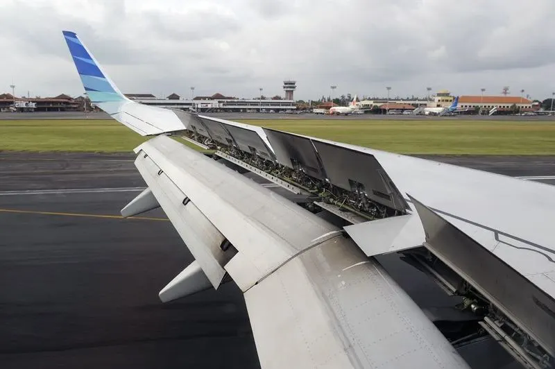
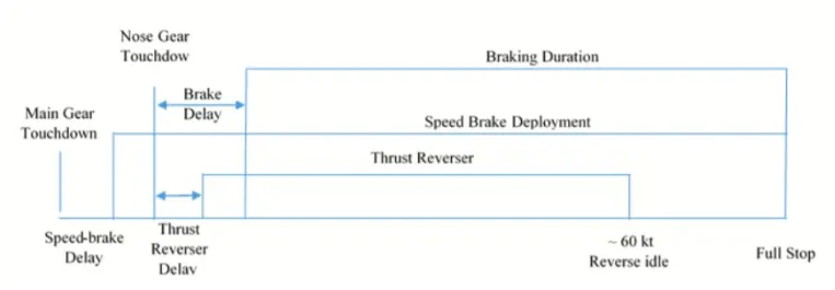
Braking is the challenging job for the most of the pilot especially landing in rainy seasons or bad weather condition. In order to safe landing pilot usually makes the use of spoilers and reverse thrust method in order to have a safe landing so that the energy required to apply the brakes on the tyres reduced and there by avoid the skidding of tyre.
In order to determine the brake force on aircraft,
k=1/2 m v^2
m is mass
v is velocity
A typical commercial landing speed will range betweem 150 to 165 mph. Passenger flight will about 166 to 172 mph.
Part B
6,
A, The forces acting on the vehicle for push or pull the aircraft are rolling resistance force, aerodynamical force and hill climbing force.
Rolling resistance force;
Frr= Urr * m * g
where, Urr is the rolling resistance coefficent
m is the total mass of vehicle (vehicle mass + payload)
g = 9.8 m/s^2
Here Urr = 0.013
Aerodynamic force;
Fad = 1/2 * ρ * v^2 * A *(Cd_t + Cd_a)
where, ρ is air density (normally 1.25 Kg/m^3)
A is frontal area of vehicle
Cd_t is air drag coefficent of towing vehicle
Cd_a is air drag coefficent of aircraft
v is the velocity of the vehicle in m/s
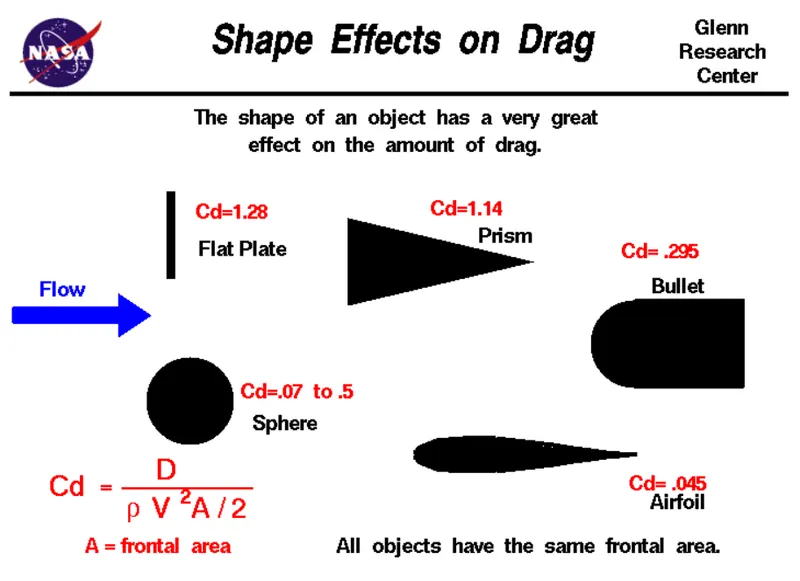
Here we taking the Cd_t = 0.5 and Cd_a = 0.045
Hill climbing force;
Fhc = m* g* sinϕ
Where, ϕ is the inclination angle in radian
We are considering ϕ = 0 (usually towing will be in flat area)
The total power required for the towing vehicle to push or pull the aircraft is workout in an excel sheet,
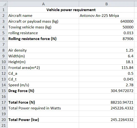
From this we got that the power required to pull the aircraft is 245.226 kw.
B,
The force and power required to pull the aircraft is calculated using the simulink is attached below.
First rolling resistance force is calculated,
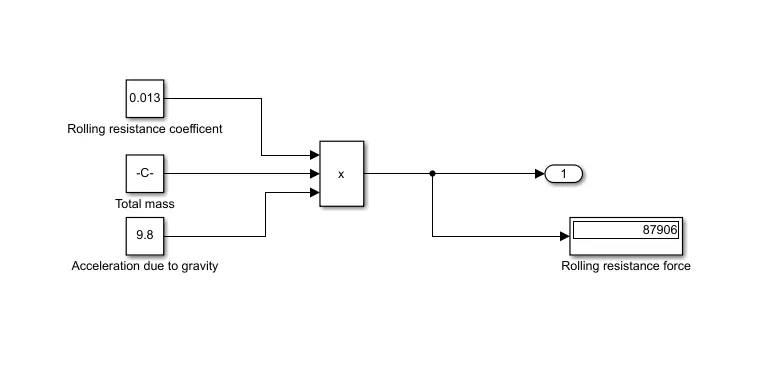
Now, calculate the dragging force,
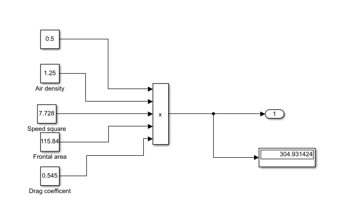
Total force is calculated by adding the rolling resistance force and dragging force together, the power can be calculated by multiplying the force and velocity,
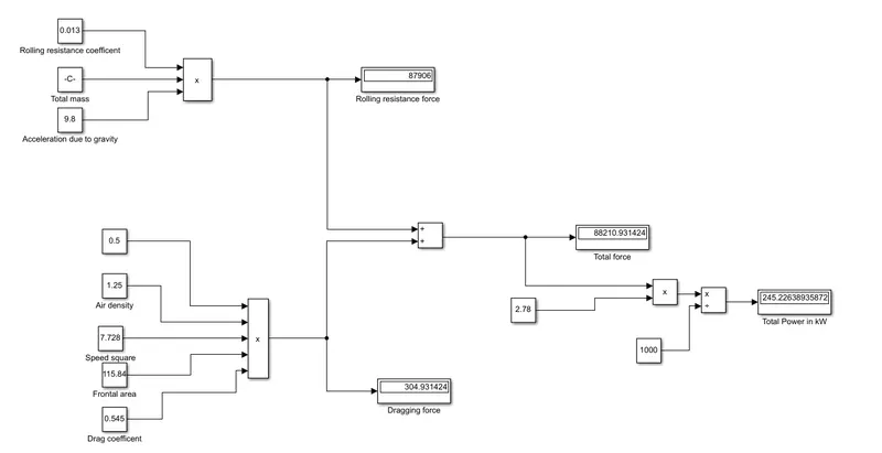
Total power = 245.226 kW
7, A,
Aircraft mass = 640000 kg
Towing vehicle mass = 50000 kg
Rolling resistance coefficent = 0.013
Air density = 1.25 kg/m^3
Cd_t = 0.045
Cd_a = 0.5
Frontal area = 115.84 m^2
velocity = 2.78 m/s
Consider the radius of towing vehicle wheel = 0.5 m
From above parameters we get that,
Total traction force = 88210.94721 N
Power required = 245.226 kW
Now calculate the torque required by the vehicle to pull the aircraft,
Torque = Force * Radius of wheel = 88210.94721 * 0.5 = 44105.473 Nm
Consider the towing time is t = 4 min
The energy required = Power * time = 16.34 kWh
So for this application an electric motor either induction motor or BLDC of above parameters are required.
Consider an motor of input power 300kW , we have the output power of the vehicle is 245 kW.
So the duty cycle D = output/input = 0.8166
The duty cycle = 81.67%
The block diagram of powertrain ,
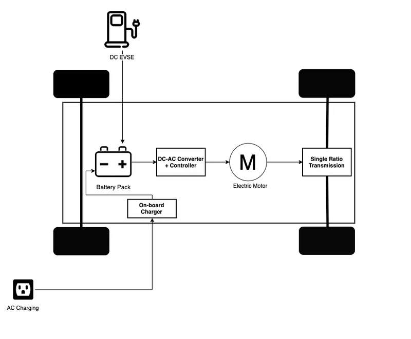
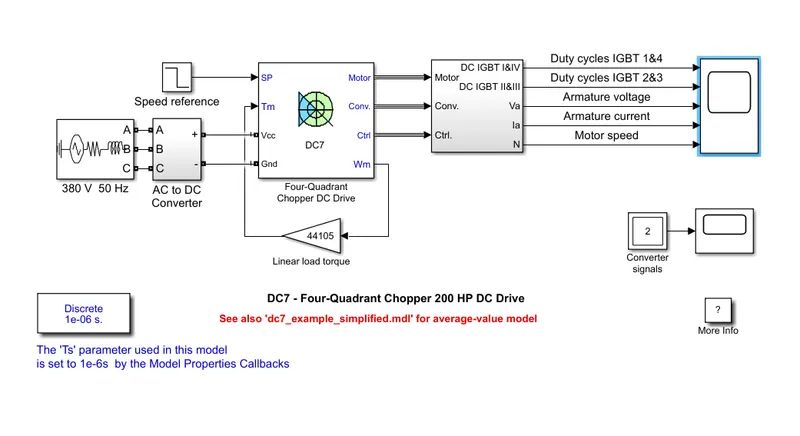
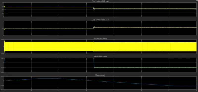
B,
Design the parameters in excel sheet
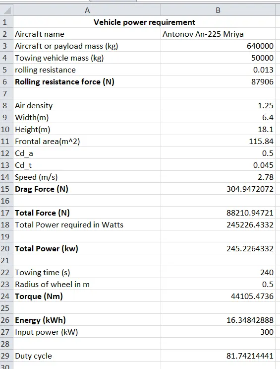
Excel file is attached.