Project 2 Thermal modeling of battery pack
AIM: Thermal Modeling of Battery Pack
The Lithium-ion batteries are widely used as energy sources in different hybrid and electric vehicle, however, the operation characteristics of the battery in such vehicle are strongly dependent on the operation temperature and therefore, with purpose to improve these characteristics a good thermal control system should be utilized.
The temperature of a Lithium battery cell is important for its performance, efficiency, safety, and capacity and is influenced by the environmental temperature and by the charging and discharging process itself. Therefore, a thermal model of the battery is used in order to calculate and estimate the cell temperature.
So, for 10-cell series lithium ion battery here I used MATLAB Simulink for finding thermal effect and life cycle performance related to temperature, charge and discharge.
Lithium-Ion Battery Pack with Fault is to simulate a battery pack consisting of multiple series-connected cells in an efficient manner. It also shows how a fault can be introduced into one of the cells to see the impact on battery performance and cell temperatures. For efficiency, identical series-connected cells are not just simply modelled by connecting cell models in series. Instead a single cell is used, and the terminal voltage scaled up by the number of cells. The fault is represented by changing the parameters for the Cell 6 Fault subsystem, reducing both capacity and open-circuit voltage, and increasing the resistance values.
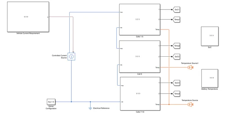
A detail design of MATLAB Simulink model for thermal modelling is given as:-
Vehicle Current Model:
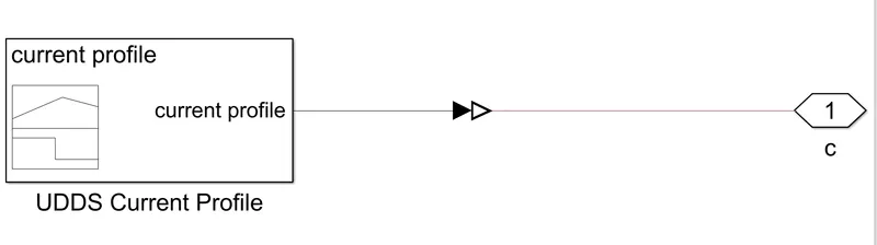
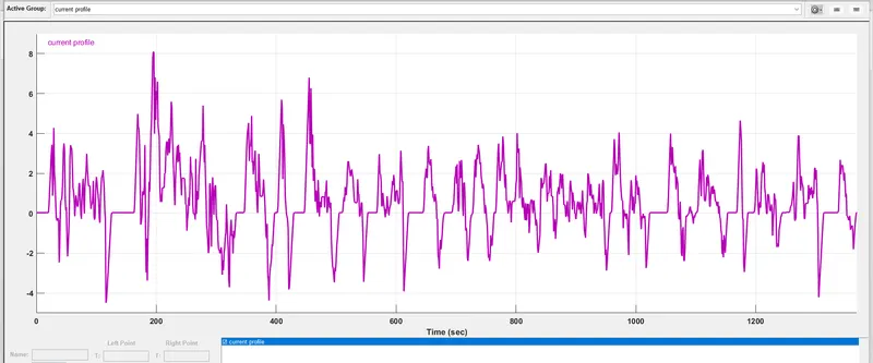
- In vehicle current requirement subsystem block,the signal builder block used to apply UDDS current profile and simulink-ps converter block used to convert the simulink signal to physical signal.connectin port block used to output the signal.
Cell 01 to 05 Subsystem;
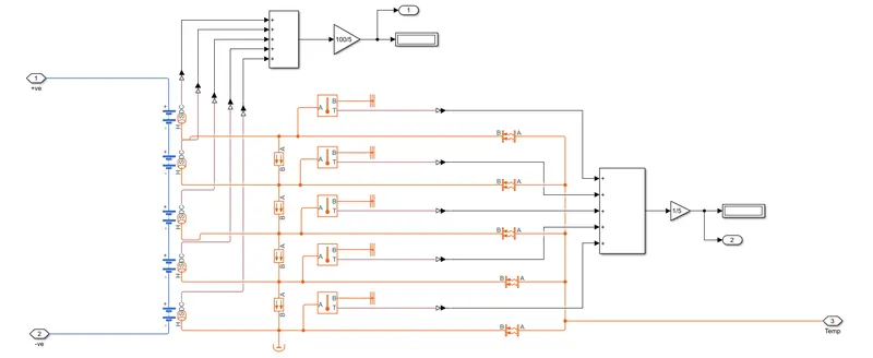
- In this module we used the 5 table based battery block in which we put the datasheet value on it.here i put the battery specification like, 2.5Ah capacity,initial temp.value is 298K etc.and this 5 cell are connected in series.
- Here we use the conductive heat transfer block in which we put the thermal conductivity is 401 W/(K*m),area is 10 m^2,and thickness is 0.1m.
- Here we use the convective heat transfer block in which we put the heat transfer co-efficients is 20 W/(K*m^2),area is 10 m^2.and one end of this block is connected to thermal source and other is connected to perticular cell.
- Here we use perfect insulator also.
- Here we use temperature sensor to sense the temperature of cell and display the value in scope and dashboard.also it one end connected to thermal referance.
- SOC of every cell is also calculate by using add and gain block,and display the soc value in % in display block.
Cell 06 Subsystem;
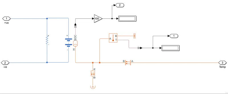
- In this module we used the table based battery block in which we put the datasheet value on it.here i put the battery specification like, 2.5Ah capacity,initial temp.value is 298K etc.and addition to that accross the battery terminal we use the 5 ohms resistor to show the this is the faulty cell.
- Here we use the conductive heat transfer block in which we put the thermal conductivity is 401 W/(K*m),area is 10 m^2,and thickness is 0.1m.
- Here we use the convective heat transfer block in which we put the heat transfer co-efficients is 20 W/(K*m^2),area is 50 m^2.and one end of this block is connected to thermal source and other is connected to perticular cell.
- Here we use perfect insulator also.
- Here we use temperature sensor to sense the temperature of cell and display the value in scope and dashboard.also it one end connected to thermal referance.
- SOC of every cell is also calculate by using add and gain block,and display the soc value in % in display block.
Cell 07 to 10 Subsystem;
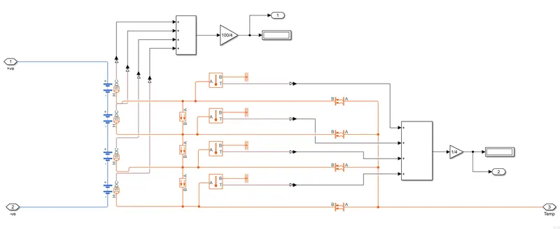
- In this module we used the 4 table based battery block in which we put the datasheet value on it.here i put the battery specification like, 2.5Ah capacity,initial temp.value is 298K etc.and this 4 cell are connected in series.
- Here we use the conductive heat transfer block in which we put the thermal conductivity is 401 W/(K*m),area is 10 m^2,and thickness is 0.1m.
- Here we use the convective heat transfer block in which we put the heat transfer co-efficients is 20 W/(K*m^2),area is 10 m^2.and one end of this block is connected to thermal source and other is connected to perticular cell.
- Here we use perfect insulator also.
- Here we use temperature sensor to sense the temperature of cell and display the value in scope and dashboard.also it one end connected to thermal referance.
- SOC of every cell is also calculate by using add and gain block,and display the soc value in % in display block.
SOC Calculation Model:
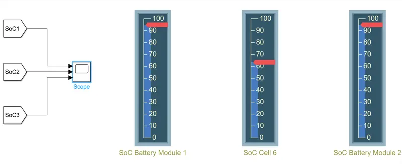
- Here we use the 3 goto block and 3 from block and scope to analyze the change in soc of 3 different cell module.
Temperature Calculation Model:
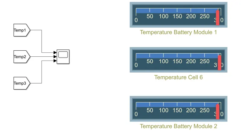
- Here we use the 3 goto block and 3 from block and scope to analyze the change in temperature of 3 different cell module.
Result:
A] At 25oC:
1] SOC OF Different Module [%]:
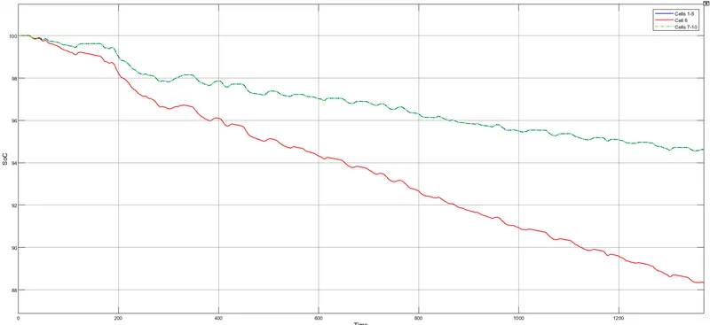
- Model 2 has a much steeper slope than the others bcoz of added 5 ohm resistor.a load(in the form of resistor) with a resistance of just 5 ohms will draw in more current compared to no added load.wich means greater rate of discharge and hence more drainage of SOC.
2] Temperature Change In Module [K]:
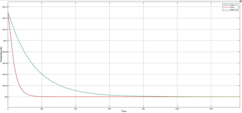
- Initial temperatre of batery pack is set to 298K.
- Ambient temperature supplied is 298K.
- The temperature of module 2 rises quickly to 298k compared to other module due to increased surface area contact and its position being in the center of the battery pack and in addition to the fact that there is also added 5 ohm resistance in mode 2.
B] At 45oC:
1] SOC OF Different Module [%]:
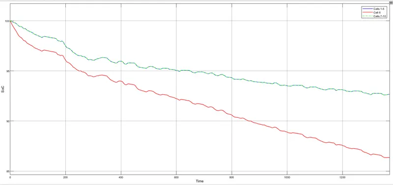
- Model 2 has a much steeper slope than the others bcoz of added 5 ohm resistor.a load(in the form of resistor) with a resistance of just 5 ohms will draw in more current compared to no added load.wich means greater rate of discharge and hence more drainage of SOC.
2] Temperature Change In Module [K]:
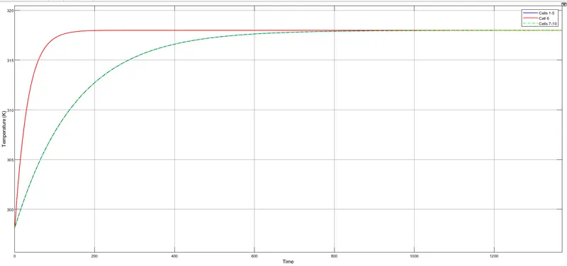
- Initial temperatre of batery pack is set to 298K.
- Ambient temperature supplied is 318K.
- The temperature of module 2 rises quickly to 318k compared to other module due to increased surface area contact and its position being in the center of the battery pack and in addition to the fact that there is also added 5 ohm resistance in mode 2.