Week -2
1,
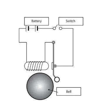
The above shown is arrangement of door bell using solenoid, when the switch is closed the electromagnet receives electrical power from the battery and pulls the metal arm to hit the bell producing sound.
The simulink model is shown below,
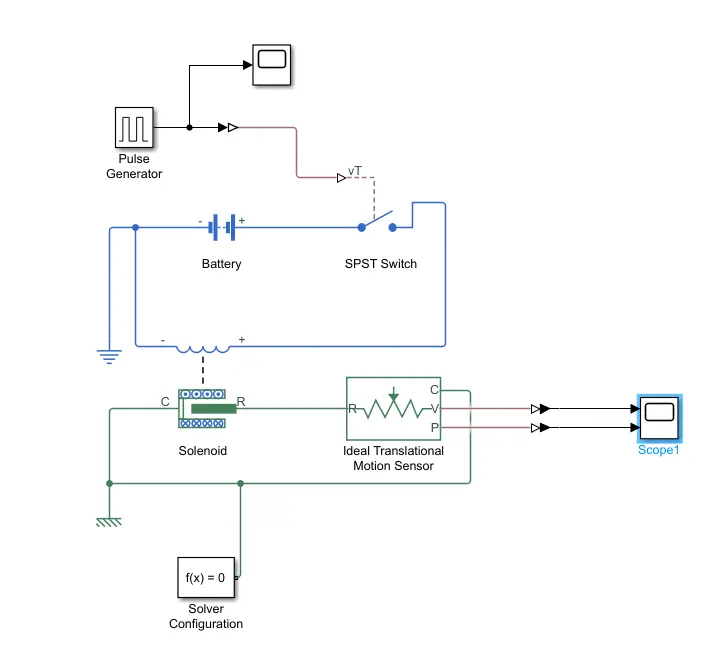
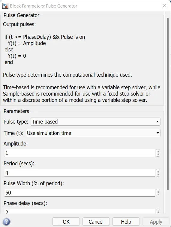
- Pulse generator block generates the square wave pulses at regular intervals. Here input signal of pulse 1 unit amplitude, 4 second period, having duty cycle 50% used, also there is a 2 second delay.
- Simulink to PS converter used to convert simulink to physical system.
- SPST switch is provided, it works when physical signal reaches , it compares and if greater than threshold value the electrical circuit closes.
- The current flows through the solenoid and energises the solenoid which results to deflection which makes the ring sound.
- A mechanical translational reference is attached to the C port of solenoid.
- Scope is used to plot and analyse the graphs.
Results;
Pulse width,
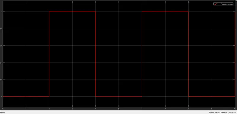
Position vs Time & Velocity vs Time ;
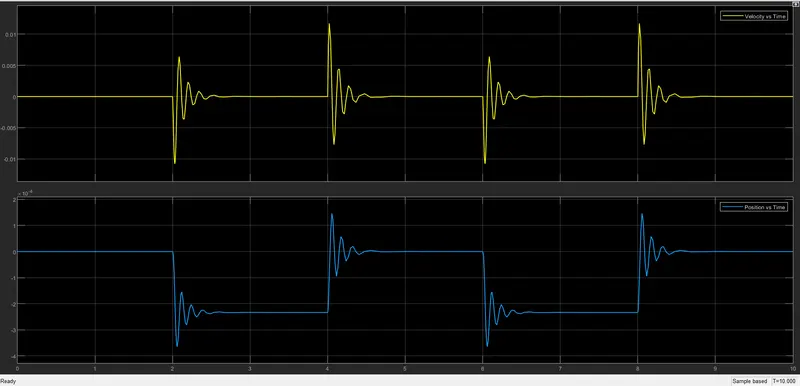
From the output graph we can see that a slight disturbance occuring at 2 seconds after switch is closed.
2,
A thermistor (or thermal resistor) is defined as a type of resistor whose electrical resistance varies with changes in temperature. Although all resistors’ resistance will fluctuate slightly with temperature, a thermistor is particularly sensitive to temperature changes. Thermistors act as a passive component in a circuit. They are an accurate, cheap, and robust way to measure temperature. While thermistors do not work well in extremely hot or cold temperatures, they are the sensor of choice for many different applications.
There are two types of thermistors:
- Negative Temperature Coefficient (NTC) Thermistor
- Positive Temperature Coefficient (PTC) Thermistor
In an NTC thermistor, when the temperature increases, resistance decreases. And when temperature decreases, resistance increases. Hence in an NTC thermistor temperature and resistance are inversely proportional.
A PTC thermistor has the reverse relationship between temperature and resistance. When temperature increases, the resistance increases. And when temperature decreases, resistance decreases. Hence in a PTC thermistor temperature and resistance are directly proportional.
Simulink model;
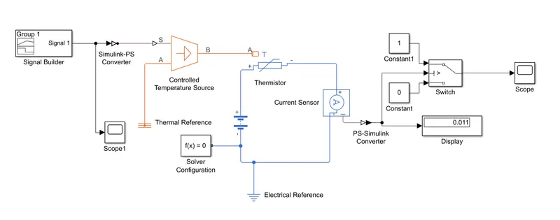
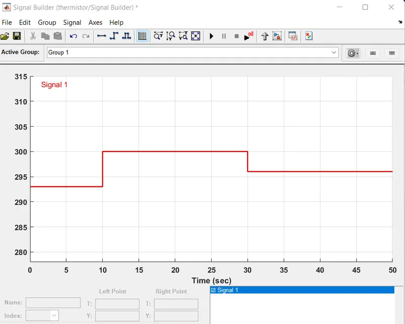
Here the input is fed through the block 'Signal builder'. The input data is given based on the initial conditions provided in the challenge, Temperature source: 20 °C from 0 to 10 seconds, 27 °C from 10 to 30 seconds, 23 °C from 30 to 50 secondsFan conditions: ON if the temperature above 25 °C, OFF otherwise.
As per the above mentioned conditions the input of the signal builder is made as shown below,
Before this signal is been fed into the Controlled temperature source the settings of the "Simulink Physical signal converter" have to be modified. The positive side of the thermistor is connected to the positive terminal of battery and the negetive side is connected to the current source (to detect the current flow in circuit).
The value of current sensor is converted to simulink and given to the display block. This is just to give the threshold value inside the switch, which has two outputs based on two conditions, if the temperature value is above the reference value, the output is 1 otherwise the output is 0. The final output is recorded in the scope.
Output;
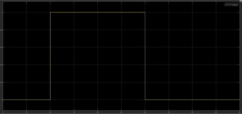
So based on the given conditions the fan should work only in the time period of 10 to 30 seconds where the temperature is above the 25 °C, which is exactly depicted in the graph shown above.