Week-7 Challenge: DC Motor Control
1, A.
Open the matlab software, goto help section and type 'speed control of a dc motor using BJT H-bridge' the model will be open. After that open that model in matlab window.
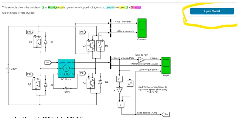
The Bipolar Junction Transistor (BJT) is operates as IGBT when used as power switching application. When conducting a forward voltage Vf is developed between collector and emitter (1v). Therefore IGBT block can used to model the BJT device.
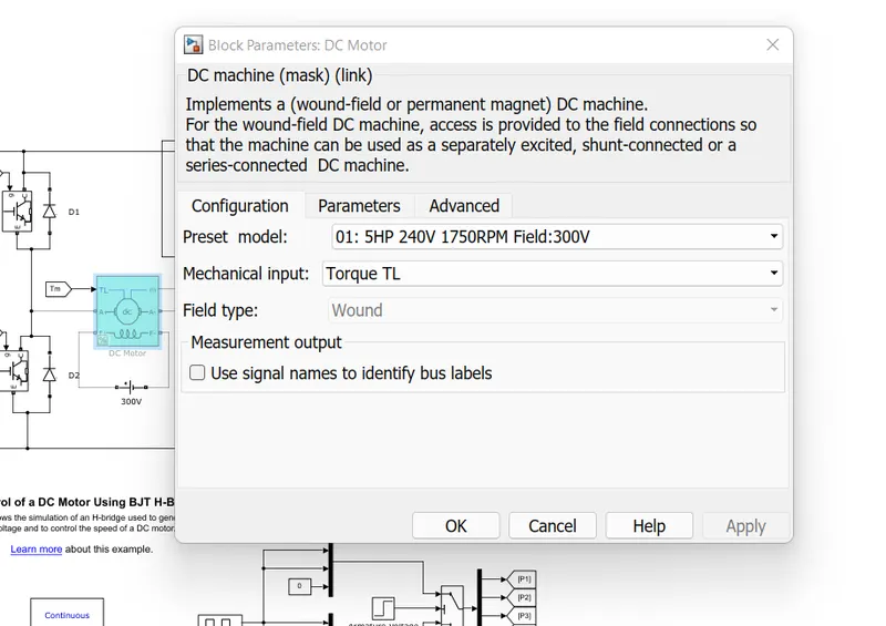
There are four IGBT s used , the dc motor is 5HP, 24v, 1750 rpm. Four IGBT s form the H Bridge configuration. Two transistors are switched simultaneously , Q1 and Q4 or Q2 and Q3.
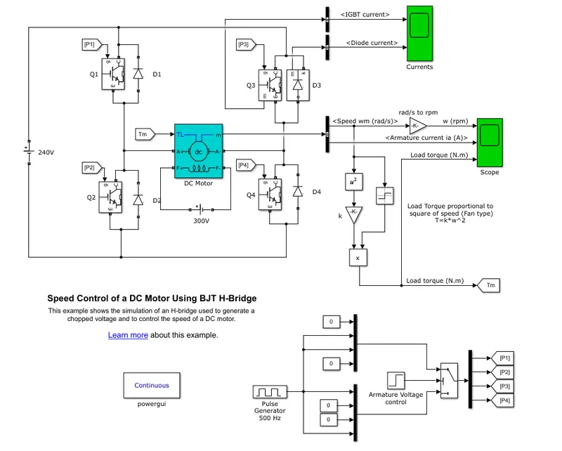
When Q1 and Q4 are fired, a positive voltage applied to the motor and diodes D2 and D3 are operate as free wheeling diodes when the Q1 and Q4 are switched off. When Q2 and Q3 are fired a negetive voltage is applied to the motor and diodes D1-D4 operate as free wheeling diodes when the Q2 and Q3 are switched off.
B.
Scope shows the motor speed, Armature current and load torque. Currents shows the current flowing in the BJT Q3 and diode D3.
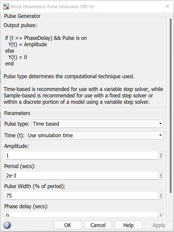
The duty cycle is 75% set in the pulse generator block.
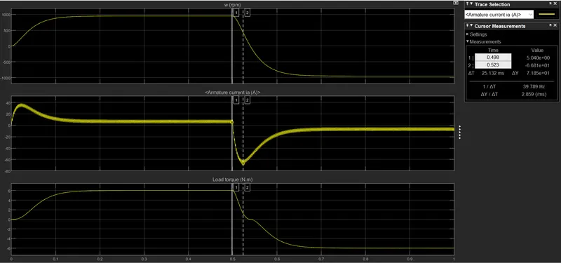
While running the simulation we get the graph of Armature current, Load torque and Speed.
For duty cycle of 75% we get,
Armature current shoot up when motor change direction from forward to reverse is about 70A which is too large and we need to reduce it by reducing the duty cycle.
Change the duty cycle into 50% in pulse generator block and again run the simulink.
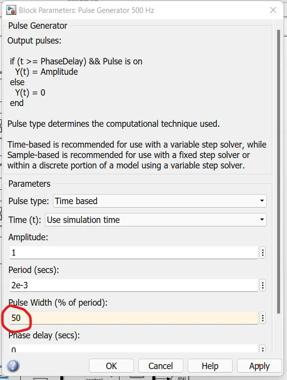
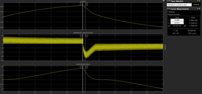
Here the current shooting is reduced to 18A. If we further reduce the duty cycle the armature current shooting will be reduce.
For lowering the current shooting we have to reduce the duty cycle.
C.
| Four Quadrant chopper | H Bridge |
| It is used for Industrial and commercial applications. | It is commonly used for robotics |
|
|
| To change the direction of rotation of motor like forward and reverse. Signals are interrupted with one another. | It has low switching frequency while comparing with the 4 quadrant chopper. |
| Armature current varies little while switching from one quadrant to another due to high switching frequency. | Armature current shoots up in the graph indicates the variation while switching forward to reverse operation. |
2,
Two quadrant chopper circuit have always positive output voltage and current vary from positive to negetive. When chopper CH1 or diode FD conducts, the load current becomes positive and load current becomes negative when CH2 or D2 conducts. The chopper CH1 and CH2 never conducts simultaneously otherwise the DC supply source is short circuited.

Open simulink in matlab, construct the type c chopper circuit using the suitable blocks from the library as shown below;
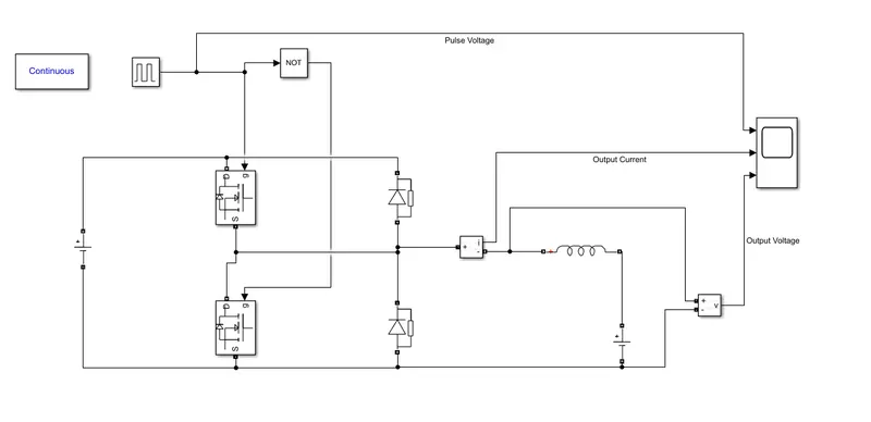
After constructing the simulink run the simulation and open the scope to see the results.
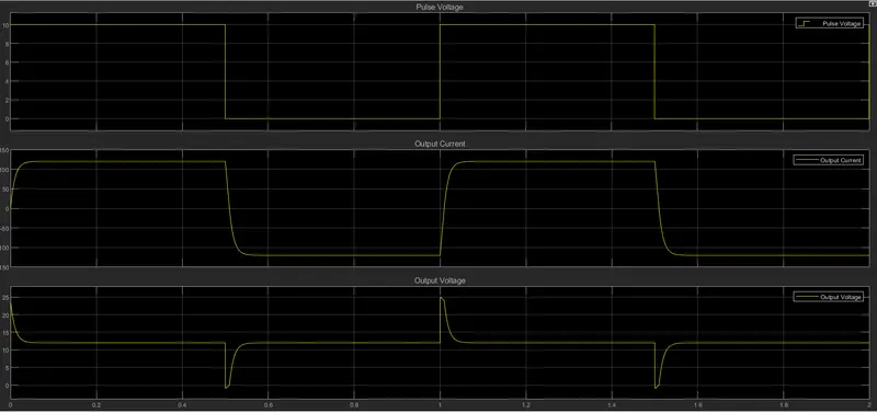
Three graphs are taken for analysis, From the scope results we can clearly see that the output voltage is always positive for the operation and the current is changing from positive to negetive.
3,
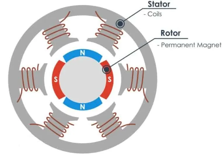
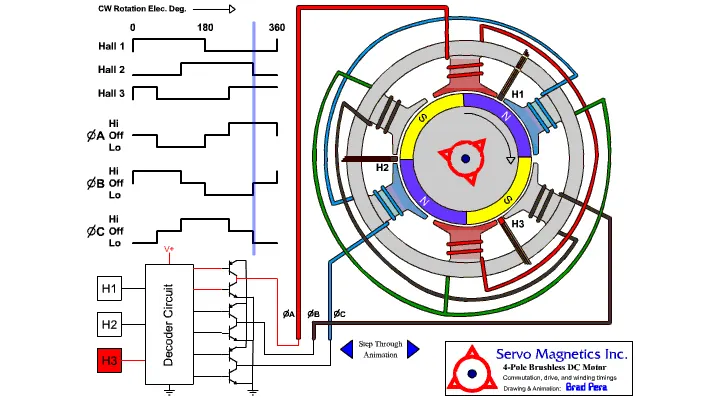
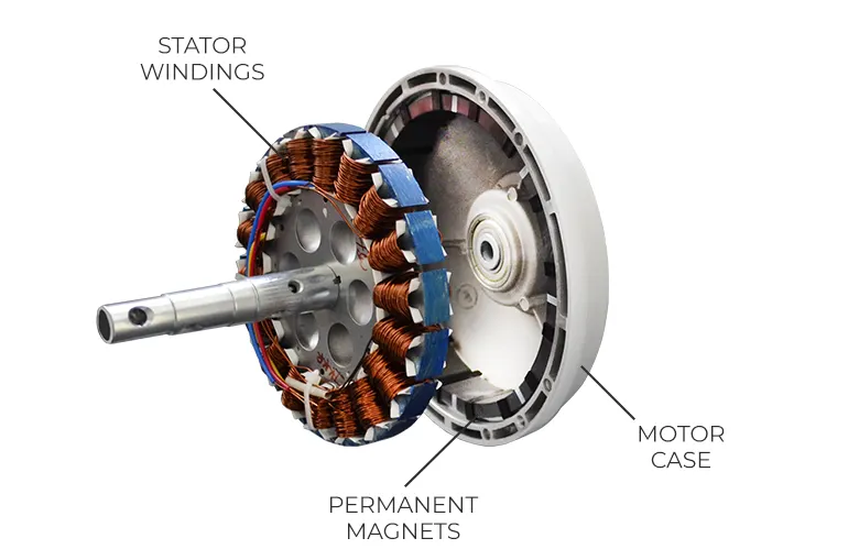
A brushless dc electric motor (BLDC motor or BL motor) also known as electronically commutated motor (ECM). It uses electronic closed loop controller to switch dc currents to the motor windings produces magnetic fields which rotates and the permanent magnet rotor follows it. The controller adjest the phase and amplitude of the dc current pulses to control the speed and torque of the motor.
The construction is similiar as a PMSM or an Induction motor. BLDC motor works on the principle similar to that of a Brushed dc motor. The Lorentz force law which states that whenever a current carrying conductor placed in a magnetic field it experiences a force. As a consequence of reaction force, the magnet will experience an equal and opposite force. In the BLDC motor, the current carrying conductor is stationary and the permanent magnet is moving. When the stator coils get a supply from source, it becomes electromagnet and starts producing the uniform field in the air gap. Though the source of supply is DC, switching makes to generate an AC voltage waveform with trapezoidal shape. Due to the force of interaction between electromagnet stator and permanent magnet rotor, the rotor continues to rotate. The switching of windings as High and Low signals, corresponding winding energized as North and South poles. The permanent magnet rotor with North and South poles align with stator poles which causes the motor to rotate.
Advantages of BLDC Motor :-
- Less overall maintenance due to absence of brushes.
- High speed and high efficiency.
- Smaller motor geometry and lighter in weight than both brushed type DC and induction AC motors.
- Long life as no inspection and maintenance is required for commutator system.
- Less electromagnetic interference.
- Low noise due to absence of brushes.