Project 1 Mechanical design of battery pack
ANR26650M1-B, LithiumWerks Nanophosphate® 3.3V 2.5Ah Lithium Iron Phosphate Battery
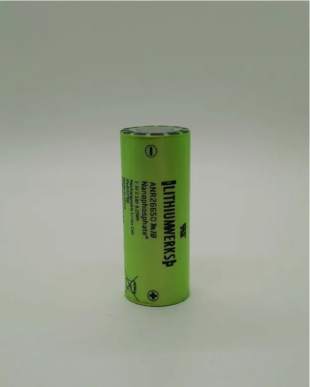
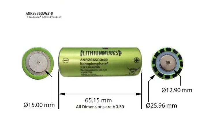
ANR26650M1-B Specifications
Nominal Ratings
Voltage: 3.3 Volts
Capacity: 2.5 Ah
Energy: 8.25 Wh
Specific Power: 2600 W/kg
Impedance (1KHz AC Typical): 6 mΩ
Cycle Life at 1C/1C, 100% DOD: > 4000 cycles
Cell Type: 26650 Lithium Ion Power Cylindrical Cell
Discharging
Max Continuous Discharage: 50 A
Max Pulse Discharge Current >50% SOC (10s): 120 A
Minimum Voltage: 2 Volts
Temperature: -30ºC to 55ºC
Charging
Recommended Standard Charge: 2.5 Amps
Max Charge Rate: 10 Amps
Max Pulse Charge Current <50% SOC (10s): 25 A
Float Voltage: 3.45 Volts
Recommended charge V & Cut-off Current: 3.6 Volts, taper to 125mA
Temperature
(reduce charging current to 250mA when under 0ºC): 0ºC to 55ºC
Mechanical
Diameter: Ø25.96 +/- 0.5 mm (1.0")
Length: 65.15 +/- 0.5 mm (2.6")
Mass: 76 g
Cylindrical Cell Primary Applications:
- Portable high power devices
- Stationary battery backup systems
- Grid stabilization energy storage systems
- Commercial truck and bus hybrid electric vehicles (HEVs)
Lithium Ion Cell Benefits:
- Power: Over 2,600 W/kg and 5,800 W/L
- Safety: Excellent abuse tolerance and environmentally friendly
- Life: Excellent calendar life, 10X cycle life vs. conventional lithium ion
Calculations per assumptions: 18 KWh battery pack
The mathematical calculation for designing of 18 kwh battery pack are as given below
#General required value depending upon a single cell:
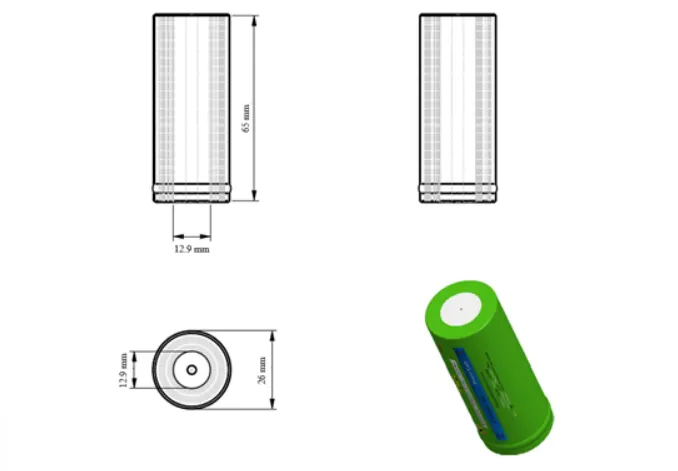
- Diameter=0.026 m
- Length=0.065 m
- Mass=0.076 kg
- Single cell voltage=3.3 V
- Capacity=6 Ah
- Max continuos charge Current(C rate)=10A
- Max Pulse charge Current(C rate)=20 A
# Mathematical Singal cell Calculations:
Volume=Pi*r^2*h
= 3.142*0.013^2*0.065
=0.03451 mm^3.
Single cell Energy=Cell Capacity*Cell Voltage
=2.6*3.3=8.58 Wh
# Calculations of high voltage battery:
Assume the vehicle range should be 250 Km and the nominal voltage also 250 V
1.Average Energy per Km=18000/250
=72 Wh/Km
2.Number of cells Connected in series=NominalVoltage of series Connections/Nominal voltage of single cell
=250/3.3= 75.75 Or 76 Cells in series
3.Energy For battery Pack(Wh)=No.Of cells Connected in series*single cell energy
=75*8.58=643.5 Wh
4.Number of cells connected in parallel=Battery pack total energy/energy for battery pack
=18000/643.5=27.97 Or 28 cells in parallel
5.Battery pack total enrgy=number of cells connected in parallel*energy for battery pack
=28*643.5=18 KWh
6.Battery Pack Capacity=single cell capacity *number of cells connected in parallel
= 28*2.6=72.8 Ah
7.Total number of cells for battery pack=76*28=2128 Cells
8.mass of the battery pack=total nuber of cells*mass of single cell
=2128*0.076=161.728 Kg
9.Total volume of battery pack=2128*0.0345=73.3125 m^3.
10.Cell peak current(A)=C(Rate)(Max pulse charge current)*Single cell capacity
=20*2.6=52 A
11.Battery Pack Peak current=cell peak current*no. of cells connected in parallel
=52*28=1456 A
12.Battery Pack Peak power(W)=Battery Pack Peak Current*Voltage of series connection
=1456*250=364000 W=364W
13.cell Continuos Current(A)=Max continuos charge current*single cell capacity
=10*2.6=26 A
14.Battery pack continuos current=cell continuos current*no.of cells connected in parallel
=26*28=728 A
# Cell Modeling\
A cell basically consist of Anode,Cathode,Seperator,positive cap,negative cap and shell.
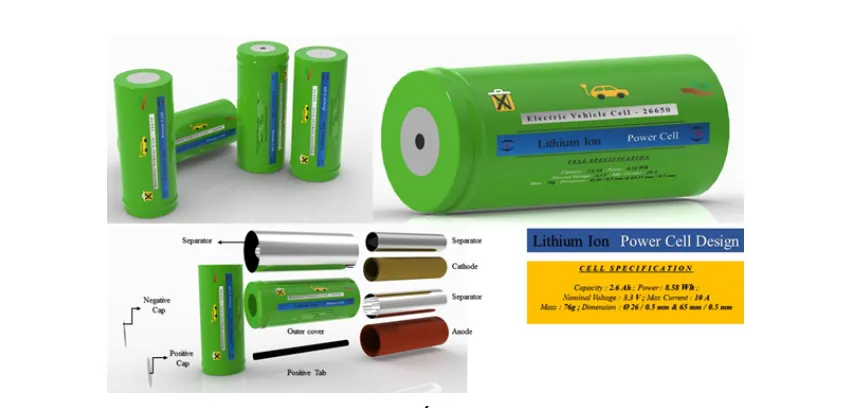
Arrangement and assembly of 7S4P Cell pack 28 cells are as shown in figure
- package:7S4P
- capacity:10.4 Ah
- Voltage:23.1 v
- cells:28 cells
- Pack Capacity:240.24 Wh
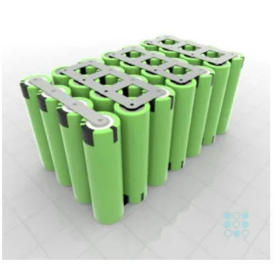
Assembly of The full battery pack with 76S/ 28P.The arrangement of the pack is as follows:
Sigle pack:28 cells with 7S/4P
Number of pack :number of cells /one pack cells=2128/28=76 Modules
But here we need to arrenge the 11 modules in series and 7 modules in parallel
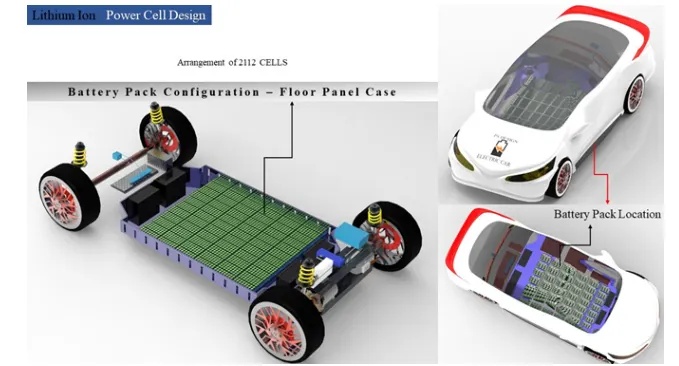
Here also configure battery pack into electric vehicle lower floor panel case,a simple layout of the battery pack in a electric vehicle is shown below,
#Design of cell Holder(Bottom and Top)
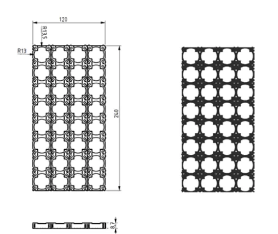
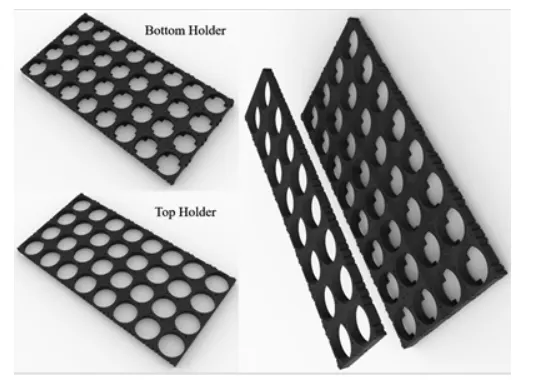
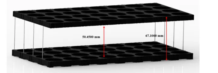
The mainn function of a battery holder to keep cells fixed in place safely and securely also it is used to keep cells in a proper arrangement so that there will be a decrease innmechanical vibrations, and have a better thermal runway in between the celll gaps.Most of the cell holder is made up of ployproylene or nylon bodies rated for 80-100 Degrree celcious.
A dimensions and 3D is shown in figure below:
# Design of Pack Cover:
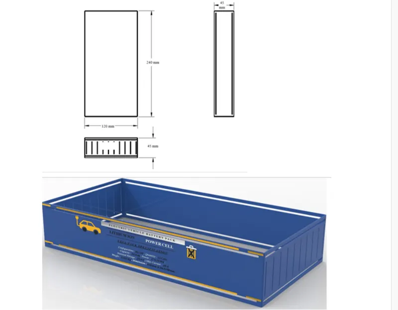
Basically ,apck cover is made up of aluminium and the reason behind is to keep battery pack lightweight.The casing /cover thickness is 0.5 mm and design is as shown below:
A bottom cover is shown to cover below the botttom battery holder.

# Design of lower floor case battery pack:
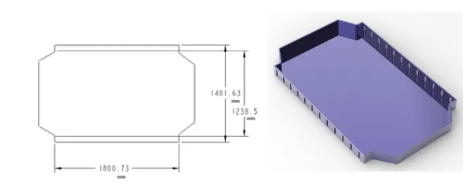
basically,the lower case is apart which is fitted in an electric vehicle for the assembly of the battery pack.A lower case is also made up of aluminium and it has top cover and bottom cover to battery pack from dust and environmental pollution.
The design of the lower case is shown
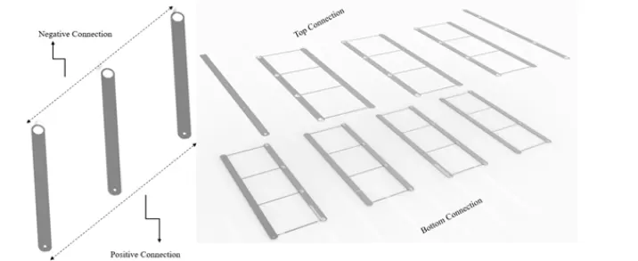
A positive and negative clip is used to connect the battery end cap i.e. + and - .design is as shown in figure:
# Battery Welding Process
Battery Tab Welding
Joining the individual batteries together with a collector plate that has tabs for the individual cells to be welded to both the positive and negative terminals is a critical manufacturing step for battery pack welding. A reduced number of collector plate-to-busbar connections is also required by several packs.
Many factors must be considered when choosing the right battery pack welding process, including the materials to be welded, joint shape, weld access, cycle time and budget, as well as manufacturing flow and production needs.
Welding is a critical technique for a battery’s proper operation. Oversights can impair the battery’s performance and range, weaken its mechanical strength, lessen its thermal efficiency, and potentially put it in danger.
To make all of the necessary tab-to-terminal connections, various welding processes are used (foil-to-tab, tab-to-busbar, etc.) Ultrasonic bonding, laser welding, resistance welding, and micro TIG welding are some of these approaches. The suitability of one approach over another is determined by the criteria, such as the combination of materials and tab thickness.
What is a Battery Tab?
The positive and negative connectors that transport the electrical current through the cells are known as battery tabs or terminals. Each tab is connected to a busbar (or collector plate) on the module, which redistributes positive and negative current to new terminals. The battery pack is made up of several modules connected in the same way.
Tabs are connected to current collectors, or foils, constructed of highly conductive materials like aluminium and copper, inside the cell shell. They transport the current from the electrodes, both positive and negative.
Battery tabs serve the same purpose for all types of batteries, but they come in a variety of shapes and sizes. For each form of EV battery cell.
Tab Welding Methods
The connections between the cells and the terminals in a battery pack require hundreds, if not thousands, of welds. Tabs and terminals are connected to current collectors inside the cells as well as busbars and collector plates.
The integrity of these connections is critical to the battery’s performance, with even a 1% failure rate being a major problem. Before welding, appropriate precautions must be taken to ensure that surfaces are clean, such as laser cleaning or working in a controlled environment.
It’s not always clear when to employ which welding procedure. Let’s take a look at each one individually.
Laser welding:
Laser welding is a high-speed procedure that joins surfaces with a highly focussed beam of light. Using ultrafast moving X-Y mirrors, the laser beam is directed and moved. This gives you a lot of versatility because you can weld any joint geometry and create bespoke weld patterns.
For battery welding, pulsed fibre lasers are preferred because they produce smaller heat affected zones, decreased porosity, and less spatter. They can weld thin or thick tabs and work with copper, aluminium, steel, nickel, and other metals.
Tab-to-busbar connections and foil-to-tab welds can both be done with laser welding.
Resistance welding:
Resistance welding, often known as spot welding, is a welding technique that employs copper or tungsten electrodes charged with electrical current. An electrical current is passed between the electrodes as pressure is applied to the area to be welded. This causes heat to be generated at the contact point, which bonds the two metals together.
Foil-to-tab and tab-to-busbar welds can both be done with resistance welding. It’s a low-cost welding method that’s great for DIY battery aficionados, but it can also be mechanised.
Ultrasonic welding:
Ultrasounds are used to induce vibrations between the materials to be connected in ultrasonic bonding or ultrasonic welding. The heat generated by the quick friction between the materials is sufficient to connect them practically instantly.
This technology is utilised for foil-to-tab welding as well as ultrasonic wire bonding, which connects cells to busbars via wires.
Micro TIG welding:
Micro TIG welding, also known as pulse arc welding, creates a high-temperature plasma that melts metal in a small area using a small electrode supplied with electricity. “Micro” TIG welding, as the name implies, is for small workpieces and is hence ideal for small battery components.
This approach is suitable for tab-to-busbar welding and works well with thick copper.
Laser Cleaning for Weld Preparation
Producing high-quality joints is critical to the battery’s overall performance. It reduces energy loss and heat generation during charges and discharges, as well as improving the battery’s lifetime and mechanical reliability.
Lithium-ion batteries are the most expensive elements in electric vehicles, thus recalls must be avoided at all costs.
Before welding, manufacturers should ensure that all surfaces are completely clean. This is where high-powered laser cleaning comes in handy, as it removes coatings, electrolytes, and oxides quickly, consistently, and precisely.
# Conclusion
As from the single -cell technical data here i have designed a battery pack for the electrric which is having of 18 KW .The total number of cells are 2128 which are in the configurationn of 76S/28P.Also ,the nominal voltage from 76 series connection of battery gives (76*3.3)250 V an dthe capacity power we get from the arrangement of 28 parallel cells is 72 V.
All design is used to achieve a 250 Km range by the vehicle,Which is an assumption to calculate the battery pack.Here if we will increase the number of cells in parallel then power will increase but at that time the distance will not be achieved by the vehicle,that's why here i use 76S/28P cell configuration.