Week -2
# PROJECT NAME:SIMULINK MODEL FOR DOOR BELL AND THERMISTOR
#MODEL OBJECTIVES:
- tO MAKE SIMULINK MODEL FOR A DOOR BELL USING SOLENOID BLOCK.
- tO MAKE THE MODEL WITH THE HELP OF THERMISTOR TO SENCE THE TEMPERATURE OF A Heater AND TURN OFF OR ON THE FAN AS PER THE GIVEN CONDITIONS.
#Model 1: DOOR BELL
Making a simulink model of doorbell using solenoid block by using below parameters.
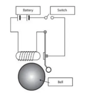
In general mechanism of door bell is simpal.The heart of doorbell is an electromagnet ,when you press a doorbell button,you complete an electrical circiut that allows household electricity to flow through the doorbell's internal electromagnet.The magnetic field generated by the electromagnet is then used to power a mechanism that createsthe doorbell sound .
#block diagram:
We have the following blocks diagram of mode is as shown
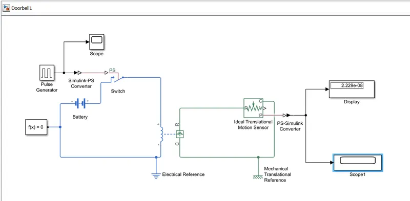
Now we are going to study these different blocks
- Pulse Generator:In general we have press thre button to ring the bell,but in simulink we have to provide some initial input to the switch.So we are providing some input with the help of pulse generator for 2 seconds.
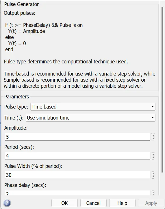
by double click on the pulse generator block we can change the amplitude ,period width and the phase delay. For us the time is given for 2 seconds
- simulink to PS converter:It converts tthe input simulink signals to physical signal.here we are giving pulse input and we want the mechanical output of switch,hense we have to convert these signals
- Switch:Ps switch block close when we provide some pulse through the converter.
- Battery:We have to aplly some voltage to oprate the bell.So that we are using battery.When switch is closed then the current passes through the circuit and bell gives the song.
- Inductance: It is simple ciol which opposes the flow of current and generates the EMF that is electromagnetic force.Which is used to turn on the solenoid.
- Solenoid:A solenoid nothing but a copper wire wounded around the solenoid iron core which turns into a magnet when electricity is passed through it.The iron core demagneties once the elecrctricity is cut off .A simple solenoid consrtuction is shown in the figure below.Asolenoid is used in the various fields such as in electrical appliances ,automotive and aerospace applications ,heavy machinery apllications and much more.
- Electrical reference: it is nothing but a elctrical ground.All the electrical blocks must be connected to the electrical referecese.
- Mechanical references:Mechanical reference is reperesentic the rotational or translational motion
- Solver configuration:Each system or physical network must be connected to the exactly one solver configuratoin block.
- Idealtrenslational motion sensor :This block represents a device that converts an across variables measured between two mechanical translational nodes into a control signal propotional to velocity or position .The snsor is ideal since does not account for inertia ,friction ,delays,energy consumption and so on.
- display:it shows the value of input data.we can specify the frequecy of the display.
- scope:display the signals generated during simulations.
#Outputs:
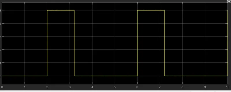
- pulse generator is used to generate the square wave pulses at regular intervals.for us the time delay is given as 2 sec .the generated wave is as shown as
2. the signals generated from the solenoid is as shown
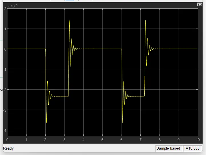
The position of the solenoid pliunger is measured using an ideal translational motion sensor connected to the circuit.The initial position of this is set to 5mm in the translational motion sensor .The scope is connected to visualise its behaviour.The spring constant and damping parameters of the solenoid block was altered to obtain the desired graph.The simulation run in 10 second and the simulation is as as shown above.
#Conclusion:
- for given time intervals of 2 seconds the loop is closed and we get the physical movement of plunger,plunger moves from port r to the port c to hit the bell and produce sound.
- When the doorbell rangs,a deflection was observed inthe scope plot.
#model 2:Thermistor
AIM: To simulate the working of fan under different conditions using a thermistor in simulink.
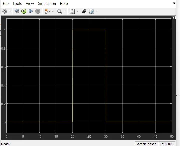
Objective : to turn on fan if the temperature is above 25 degree else off.To that use the temperature source to simulate the temperature,from 0 to 10 second at 20 degree ,from 10-30 seconds at 27 degree and from 30 -50 seconds at 23 degree.
simulink model explaination:
signal building block is added to input the values as per given conditions.
At point 1,time=0 sec to 10 sec and temperature =293k.
At point 2,time=10-30 sec and temperature is =300k.
At point 3,time=30-50 sec and temperature =296k.
Controlled temp source represents an ideal source of thermal energy,that can maintain controlled temperature difference regardless of the heat flow rate .The temperature difference is set by tyhhe physical signal port s.A positive temperature difference causes the temperature at portb B greater than the temperature port at port A.
Introduction:Thermistor is a thermally sensitive resistor which exibits a precise and predictable change in resistance proportional to the small change in surrounding temperature.Here in simulink the thermistor block which is available is apositive temperature coefficient thermistor.So here resistance of thermistor increases as as temperature increases or vice versa.The output from the thermistor is actually in the form of voltage or current.The increase in voltage /current indicates increase in temperature.
#block diagram:
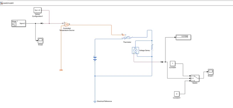
#outputs:
- output for given time interval that is for 50 sec.This is the final output .
#Block explaination
- controlled temperature source:This block represents an ideal source of thermal energy that is powerfull enough to maintain specified temperature difference across source regardless of the heat flow consumed by the system.Conneaction at point A and B are thermal obseving port corresponding to the source of inlet and outlet respectively.Port S is physical signal port through which the control signals that drives the source applied.
- Thermistor:It is type of resistor whose resistance changes with respect to temperature.This the combination of thermal and resistance.
- ResistorThis is the linear ,describe with the following equation. (V=IR)Where , V= voltage ,I =current ,R= Resistance
- Voltage sensor:It measures the voltage diffrence between two poits and converts it into physical signals .
- VOLtage source:It implements the voltage source with DC/AC and Noise components.
- Elecrical References:It represents an electrical ground.A model with elecric components must be connected to at least one elctrical reference block.
In this model the signal block is used to get temperature signal for the controlled temperature source.
The temperature of the heater is supplied to the thgermistor to sence it.Now in order to run the fan when temperature reaches the value of 298k we have to trigger the circuit with some some external supply of battery and as there is no device to calculate the resistance value of thermistor so we have attached another resistance in series across the thermal in series.The voltage sensor is attached across the resistor to calculate the voltage drop into it and this voltage value is input as thresold value to the switch to start the fan and fan will go on when thresold value is more than 0.109.
#ERRORS:
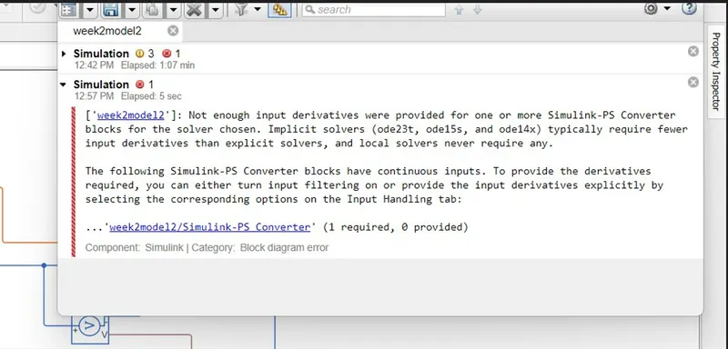
This type of error i faced due to small mistake that i forget to make changes in simulink to ps converter block.
#conclusion:
Hense we can simulate the thermistor model for on and off the fan at perticular given temperature in simulink
#Google drive links
1.for door bell
https://drive.google.com/file/d/1UEySetpKxyOQOXXmSSOkt186VrfMYlVR/view?usp=sharing
2.for thermistor
https://drive.google.com/file/d/1KsiSLE8KLeVpuiT_uhFMVUn9mtQJy5X-/view?usp=sharing