Project 1 Mechanical design of battery pack
Objective:- Battery pack capacity: 18 kWh
Cell: ANR26650M1-B
Prepare a detailed battery pack drawing along with its enclosure. State your assumptions.
Introduction:-
A123’s high-performance Nanophosphate lithium iron phosphate (LiFePO4) battery technology delivers high power and energy
density combined with excellent safety performance and extensive life cycling in a lighter weight, more compact package. Our cells have low capacity loss and impedance growth over time as well as high usable energy over a wide state of charge (SOC) range, allowing our systems to meet end-of-life power and energy requirements with minimal pack oversizing.
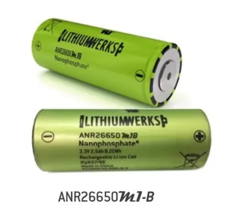
Lithium Werks’ 26650 cells are best for Power Safety Life applications. They deliver very high power due to their use of patented Nanophosphate® battery technology. Based on lithium iron phosphate chemistry (LiFePO4), the cells are inherently safe over a wide range of temperatures and conditions. Whether the application requires outstanding cycle life or stable float reliability, the Lithium Werks’ 26650 cells are suitable for a wide variety of power, pulse, or stand-by applications.
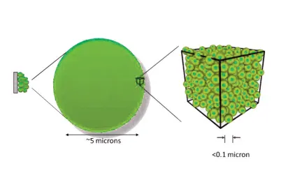
Nanophosphate battery technology offers thermal-stable chemistry, faster charging, consistent output, low capacity loss over time, and superior total cost of ownership (TCO). It provides the foundation for safe systems while meeting the most demanding customer requirements. Multiple layers of protection are employed at the chemistry, cell and system level to achieve an energy storage solution with superior safety and abuse tolerance compared to metal oxide lithium-ion chemistries.
Specification:-
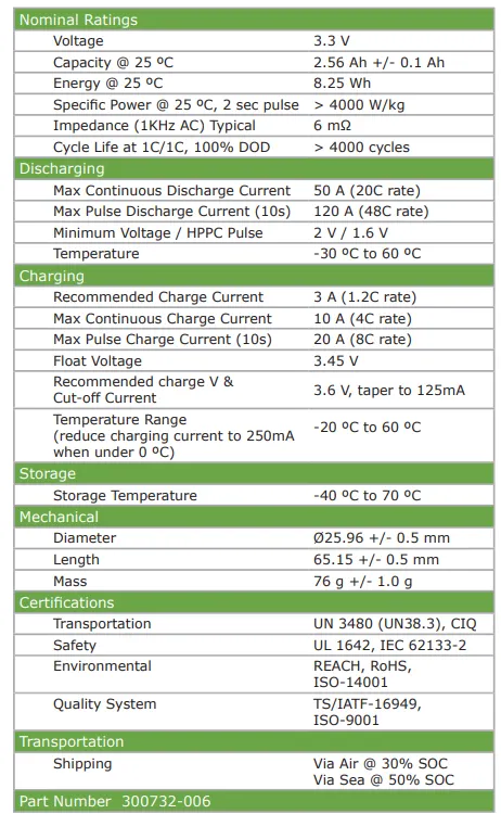
By this specification list we will consider some parameters for the calculation of Battery pack.
Dimension:-
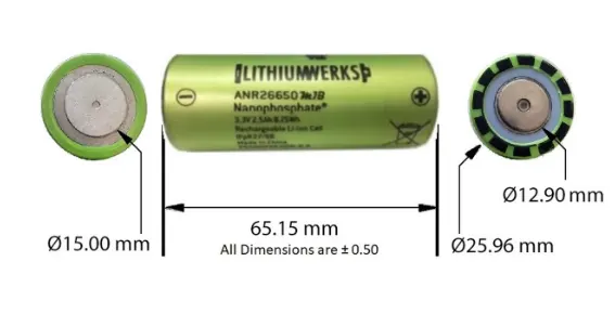
Majorly we have dimension such as:-
Height- 65.15mm
Diameter- 25.96mm
Radius- 12.90mm
Charging condition:-
When charging and discharging a battery pack, the current and voltage applied to any cell in the pack shall not be exceeded for the given conditions under which the cell are exposed. Appendix A details the limits the cells must be kept within for a given cell’s temperature and cell’s state of charge. This section covers the following topics.
Charger Limits:-
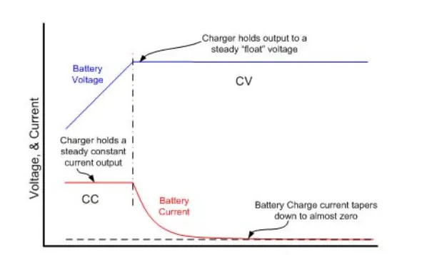
When charging or recharging Lithium Werks cells in a battery pack, the charger should limit its output current and
voltage to match that of the battery pack configuration. During a recharge, the charger shall apply a constant
current (CC) charge followed by a constant voltage (CV) charge. In addition, the charger shall cease charging
when either:
• Any one cell in the series string, has exceeded its maximum recommended charge voltage, or
• The temperature measured in the pack has gone outside the recommended range for charging
Application:-
- COMMERCIAL SOLUTIONS
1)- Advanced lead acid replacement batteries for:
2)- Datacenter UPS
3)- Telecom backup
4)- IT backup
5)- Autonomously guided vehicles (AGVs)
6)- Industrial robotics and material handling equipment
- GOVERNMENT SOLUTIONS
1)- Military vehicles
2)- Military power grids
3)- Soldier power
4)- Directed energy
- GRID SOLUTIONS
1)- Frequency regulation
2)- Renewables integration
3)- Reserve capacity
4)- Transmission and distribution
- TRANSPORTATION SOLUTIONS
1)- Hybrid, plug-in hybrid and electric vehicle battery systems for:
2)- Commercial vehicles
3)- Off-highway vehicles
4)- Passenger vehicles
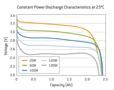
Here we have some data sheet output graph of the above cells where it is showing its constant power Discharge characterstics. At specific temp.
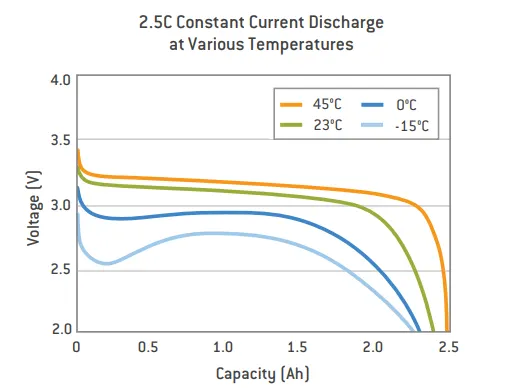
Here we have constant current discharge characterstics at various temperature.
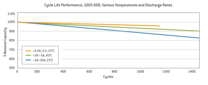
Cycle life performance of the cell at various temprature and discharge rates.
Battery Pck calculation:-
- Cell radius- 0.13m
- Cell height- 0.065m
- Cell capacity- 2.56Ah
- Weight of cell- 76g
- Nominal Voltage- 3.3V
- Power- 4000W/Kg
Therefore,
Cell volume- pi*(cell radius)*(cell height)
= 3.14*0.13*0.065
= 2.653x10^(-3) mtr cube
Cell Energy- (Cell voltage)*(Cell capacity)
= 3.3*2.56
=8.45Kw
Total battery pack energy required 18Kwh or 18000Wh
Now let's consider total battery pack voltge is 200V.
Therefore Total battery pack capacity- (Total battery pack energy)/(Total battery pack voltage)
= 18000/200
= 90Ah
Now we have battery pack capacity and voltage so we need to calculate the configuration of the cells which is as follows.
No of cells in parallel- (Total battery pack capacity)/(Nominal cell capacity)
= 90/2.56
=35.16
Total no of cells in parallel= 36Nos.
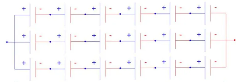
No of cells in series- (Total battery pack voltage)/(Nominal cell voltage)
= 200/3.3
= 60.6
Total no of cell in series= 61Nos
Now we have a battery pack comibination of 36P61S
So total no of cells= 36*61
= 2196

Total no of cells= 2196Nos.
Now we have to calculate the dimension of battey pack
Length of battery pack- (No of cells in series*cell diameter)= 36*0.026
= 0.963m
Width of the battery pack- (No of cells in parallel*cell diameter)= 61*0.026
= 1.586m
Height of battery pack- Height of the cell= 0.065m
Therefore,
Area of the battery pack- (Length of battery pack*Width of battery pack)
= 0.963*1.586
= 1.53 Sqm
Volume of battery pack- (Area of battery pack*Height of battery pack)
= 1.53*0.065
= 0.099 mcube
Total weight of battery pack- (Total no of cells)*(Each cell weight)
= 2196*76
=166.896Kg
Components required for Battery pack:-
- Cells
- Nickel Strip
- PVC heat sink film
- Spot welder
- connected
- Cell holder
- Solder
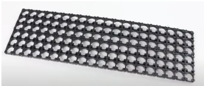
Step 1:- The first step is to start snapping the sqaure the cell holder together. One can use the cell terminal block but they will take more space than a hexagonal block.
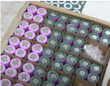
Step 2:- This shows the cells which we have and which we need to keep in these holder or fix in these holders.
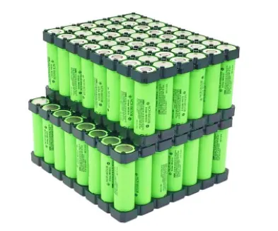
Step 3:- Place all cells into cell holders. And after that cover these cells by another cell holders plate to fix it properly.
Step 4:- Now we will be connecting the cells by Nickel strip by spot welding process. We have cell configuration by series and parallel combination of cells. So by these strips we will make the cells configuration.
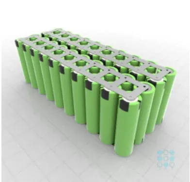
Step 5:- Connecting the heat sink to the battery pack.
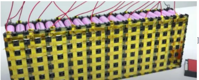
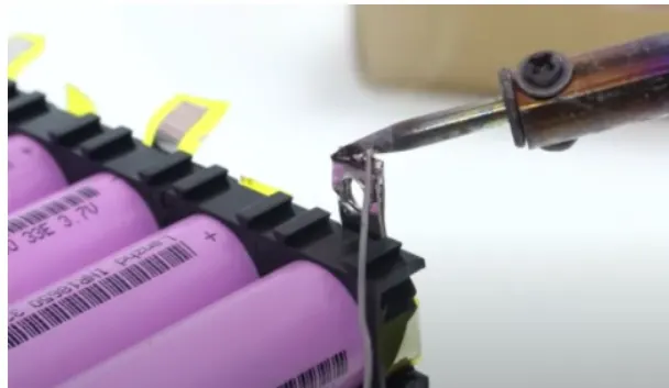
Then soldering of the battery wire
Internal structure of the battery segments has been done. Now we need to do modification over the outer part.
Step 6:- Here our battery pack ready but we need BMS over it to control the battery. Or we required manager who can manage the battery cells behavior like its temp, voltage, current, SOC, cell balancing job etc. So for these job we have installed BMS.
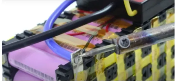
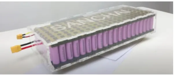
Step 7:- This is the last step of the battery pack module where we have provided the casing to the battery pack. The casing of the battery pack can be made by different ways with different mettalurgy.
Conclusion:- Here we have explained the above mentioned cell model with proper images and data sheet. Then created a mathmetical calculation for the design of the battery pack with this cell. Then the manufacturing process which we have explained with step by step with images as well.