Project 1 - Interfacing a 16*2 LCD with Arduino using I2C protocol
Overview of the Project:
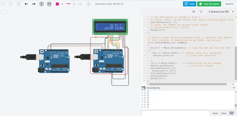
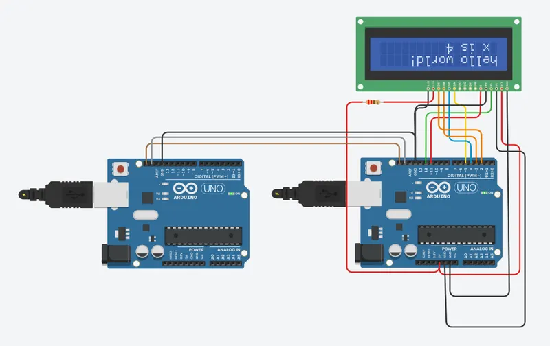
In this project implementing the Code for “Interfacing a 16*2 LCD with two Arduino’s (one for Master and one for Slave) using Inter-Integrated Circuit (I2C) communication protocol” by sending the message to LCD using I2C communication protocol and display the message on LCD screen.
Goals:
- Communication between Arduino and 16*2 LCD using I2C protocol.
- Displaying the message sent by Master and received by slave i.e. LCD display.
Key Highlights of the Project:
- Using the inter-integrated circuit communication protocol, transferring the data i.e. the message we want to display is sent to the LCD.
- Two Arduino’s connected to the LCD display and the communication is executed using I2C protocol between Arduino and the LDC display.
Deliverables of this project:
- Communication between the Arduino’s and LCD using I2C.
- The message passed from master to slave and displayed on the 16*2 LCD.
Expected Outcomes:
- Students will get the Knowledge of I2C communication Protocol and the Arduino.
- The Hardware connection of all components used in this project.
- Displaying the message sent by master (Arduino) and received by the slave (16*2 LCD display).
Explanation:
The LiquidCrystal library allows you to control LCD displays that are compatible with the Hitachi HD44780 driver. There are many of them out there, and you can usually tell them by the 16-pin interface.
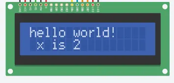
The LCDs have a parallel interface, meaning that the microcontroller has to manipulate several interface pins at once to control the display. The interface consists of the following pins:
- A register select (RS) pin that controls where in the LCD's memory you're writing data to. You can select either the data register, which holds what goes on the screen, or an instruction register, which is where the LCD's controller looks for instructions on what to do next.
- A Read/Write (R/W) pin that selects reading mode or writing mode
- An Enable pin that enables writing to the registers
- 8 data pins (D0 -D7). The states of these pins (high or low) are the bits that you're writing to a register when you write, or the values you're reading when you read.
There's also a display contrast pin (Vo), power supply pins (+5V and GND) and LED Backlight (Bklt+ and BKlt-) pins that you can use to power the LCD, control the display contrast, and turn on and off the LED backlight, respectively.
The process of controlling the display involves putting the data that form the image of what you want to display into the data registers, then putting instructions in the instruction register. The LiquidCrystal Library simplifies this for you so you don't need to know the low-level instructions.
The Hitachi-compatible LCDs can be controlled in two modes: 4-bit or 8-bit. The 4-bit mode requires seven I/O pins from the Arduino, while the 8-bit mode requires 11 pins. For displaying text on the screen, you can do most everything in 4-bit mode, so the example shows how to control a 16x2 LCD in 4-bit mode.
Hardware Required
- Arduino Board -2 no's
- LCD Screen (compatible with Hitachi HD44780 driver)
- pin headers to solder to the LCD display pin
- 220-ohm resistor
- hook-up wires
- breadboard
Before wiring the LCD screen to your Arduino board we suggest to solder a pin header strip to the 14 (or 16) pin count connector of the LCD screen, as you can see in the image further up.
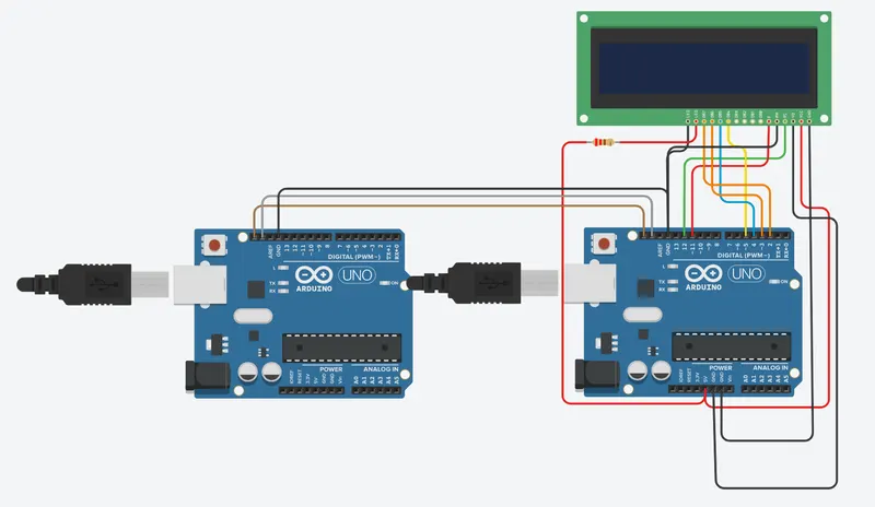
To wire your LCD screen to your board, connect the following pins:
- LCD RS pin to digital pin 12
- LCD Enable pin to digital pin 11
- LCD D4 pin to digital pin 5
- LCD D5 pin to digital pin 4
- LCD D6 pin to digital pin 3
- LCD D7 pin to digital pin 2
- LCD R/W pin to GND
- LCD VSS pin to GND
- LCD VCC pin to 5V
- LCD LED+ to 5V through a 220-ohm resistor
- LCD LED- to GND
Additionally, wire a 10k potentiometer to +5V and GND, with it's wiper (output) to LCD screens VO pin (pin3).
The I2C protocol involves using two lines to send and receive data: a serial clock pin (SCL) that the Arduino Controller board pulses at a regular interval, and a serial data pin (SDA) over which data is sent between the two devices. As the clock line changes from low to high (known as the rising edge of the clock pulse), a single bit of information - that will form in sequence the address of a specific device and a command or data - is transferred from the board to the I2C device over the SDA line. When this information is sent - bit after bit -, the called upon device executes the request and transmits it's data back - if required - to the board over the same line using the clock signal still generated by the Controller on SCL as timing.
Because the I2C protocol allows for each enabled device to have it's own unique address, and as both controller and peripheral devices to take turns communicating over a single line, it is possible for your Arduino board to communicate (in turn) with many devices, or other boards, while using just two pins of your microcontroller.
Circuit diagram:
Code:
For Master:
// Wire Master Writer

#include <Wire.h>

void setup()
{
  Wire.begin(); // join i2c bus (address optional for master)
}

byte x = 0;

void loop()
{
  Wire.beginTransmission(4); // transmit to device #4
  Wire.write("x is ");        // sends five bytes
  Wire.write(x);              // sends one byte
  Wire.endTransmission();    // stop transmitting

  //x++;
  x=x+2;
  delay(1000);
}
For Slave:
// Wire Slave Reader

#include <Wire.h>
#include <LiquidCrystal.h>

// initialize the library by associating any needed LCD interface pin
// with the arduino pin number it is connected to
const int rs = 12, en = 11, d4 = 5, d5 = 4, d6 = 3, d7 = 2;
LiquidCrystal lcd(rs, en, d4, d5, d6, d7);

void setup()
{
  Wire.begin(4);
  lcd.begin(16, 2);
  // Print a message to the LCD.
  lcd.print("hello world!");
  Wire.onReceive(receiveEvent); // register event
  Serial.begin(9600);           // start serial for output
}

void loop()
{
  // set the cursor to column 0, line 1
  // (note: line 1 is the second row, since counting begins with 0):
  lcd.setCursor(0, 1);
  // print the number of seconds since reset:
 // lcd.print(millis() / 1000);
  delay(100);
}

// function that executes whenever data is received from master
// this function is registered as an event, see setup()
void receiveEvent(int howMany)
{
  while(1 < Wire.available()) // loop through all but the last
 {
   char c = Wire.read(); // receive byte as a character
    Serial.print(c);         // print the character

  }
  int x = Wire.read();    // receive byte as an integer
  Serial.println(x);         // print the integer
  lcd.setCursor(1,2);
   lcd.print("x is");
  lcd.setCursor(6,2);
  lcd.print(x);
  delay(500);
}
Output: