Project 1
Question 1 Solution:
The data given for the car specifications as,
Power requirement (P) = 150 KW
Operating Voltage (V) = 120 V
Battery Specifications,
Battery Capacity = 3500 mAh
Nominal Voltage = 3.6 V
Nominal NMC chemistry Battery.
So First Rated current required by Car = 150 kW/120 = 1250 A
Here, We will calculate first the Cells to be connected in Series & then we will calculate for the parallel connection,
Number of cells in series = Rated Voltage requuired by car/Cell individual nominal voltage
= 120/3.6
= 33.33 Nos.
So there will be 2 possiblities for cells to be connected in parallel,
Case 1 : 33 Nos.
So For 33 Nos cells connected in parallel,
Battery Pack Nominal Voltages = 33*3.6 = 118.8 Volts
Battery Pack maximum Voltages = 33*4.2 = 138.6 Volts
Battery Pack minimum Voltages = 33*2.7 = 89.1 Volts
Case 2 : 34 Nos.
So for 34 Nos. cells connected in parallel,
Battery Pack Nominal Voltage = 34*3.6 = 122.4 Volts
Battery Pack maximum Voltage = 34*4.2 = 142.8 Volts
Battery Pack minimum Voltage = 34*2.7 = 91.8 Volts
So from above calculations we can see that Battery Nominal voltages fulfilled by case 2 as 122.4 volts which is slightly higher than our
requirement which is OK.In case 1 the nominal voltage is less 118.8 votltages which is lesser than required nominal load voltages(i.e. 120 Volts)
Thus, We are choosing 34 Nos. of cells to be connected in series.....
Now For parallel connection as we have calculated the current required by load is 1250 Ampere.
No. of cells to be connected in parallel = Rated load current/ individual cell capacity
= 1250 / 3.5
= 357.14
Thus, for parallel connection We have 2 possiblities of cells to be connected eiter 357 or 358 .
Case 1 : For 357 Nos.
Amperes that can be deliverable by 357 No. of cells
357 * 3.5 = 1249.5 Amps.
Case 2 : For 358 Nos.
Amperes that can be deliverable by 358 No. of cells
358 * 3.5 = 1253 Amps.
As per circuit requirement the exceeded current can not be tolerated because it could burn the entire circuit so we will go with case 1 for
parallel connections of cells to be 357 No.
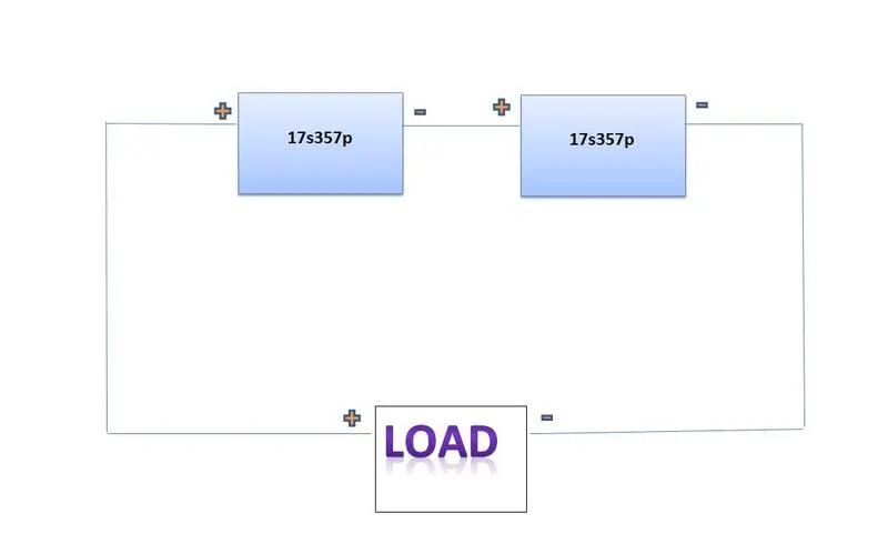
Thus , The final topology will be 34 nos. cells in series with 357 nos. cells in parallel. , We will make 2 battery pack in series connection
with 357 cells in parallel in each pack.( i.e 34s357p )
Question 1(a) Solution :
Design of Battery pack configuration will be look like as below..
(17s357p + 17s357p) = 34s357p
Question 1(b) Solution :
BMS Topology is depended upon the application of the system as well as NO. of cells to be connected in series too.Centralized topology is not compatible for our application because we have to configure more than 18 cells in series. Also Modular topology is more complex & would be more costly for our application. So we will choose Master-slave topology to design
our system. The typical strategy for it is shown below.
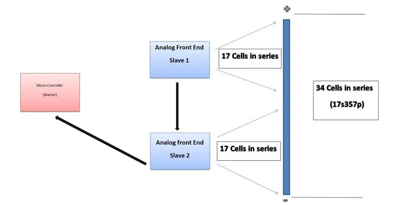
Here, The First (AFE) works as slave 1 and all the data regarding to fisrt 17 cells in series will be collected by it.It will trasport all the data to next (AFE) as slave 2. Slave 2 will collect the data of it's own 17 cells & fetches all the data of (AFE 1 & AFE 2) to micro-controller acting as a Master.So our system of (17s357p) will be handled in convinient manner.
Question 2 Solution :
We will make a simulink model for the 3s2p Topology of Battery Pack & It would be as
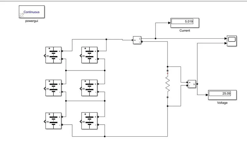
As 3s2p Topology there will be 2 modules
in parallel & 3 nos (parallel of 2 modules)
will be in series.
So the Battery Pack Voltage would be 8.3807x3 = 25.14 Volts
& the nominal Source Current would be (5.4 + 5.4) = 10.8 Amps
Here, I have taken Resistance of 5 ohms. So the Source current
would be 25.14/5 = 5.028 Amps
Conclusion: We have developed the Battery pack module with desired parameters that we wanted as Current & Voltage.We can cross verify it
with Scope output results.