Create a MATLAB model of electric car which uses a battery and a DC motor. Choose suitable blocks from Powertrain block set. Prepare a report about your model including following:
Objectives:
1. System level configurations
2. Model parameters
3. Results
4. Conclusion
Solution :
The Vehicle is a set of sub-systems.These sub-systems are designed to achieve their individual objectives for an example the Motor controller will produce the voltages according to the switching pattern & this pattern will be generated by the throttle control of the vehicle.So in order to design a Electric vehicle we have to design each & individual system by considering physical parameters of our car.
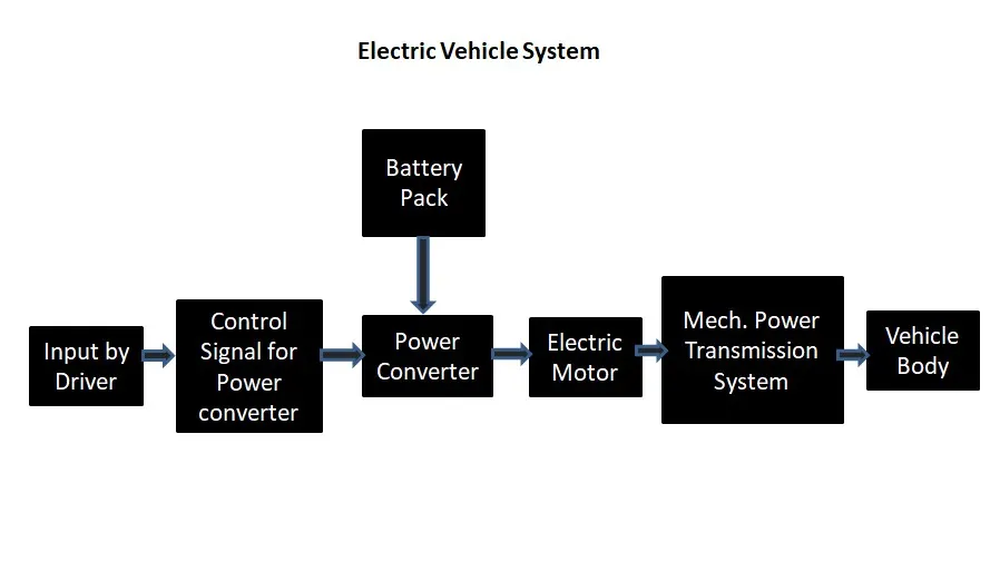
I have divided the entire vehicle in different sub-system as mentioned above I will explain individual system step by step.
1) Vehivle Body & Mechanical Power transmission system :
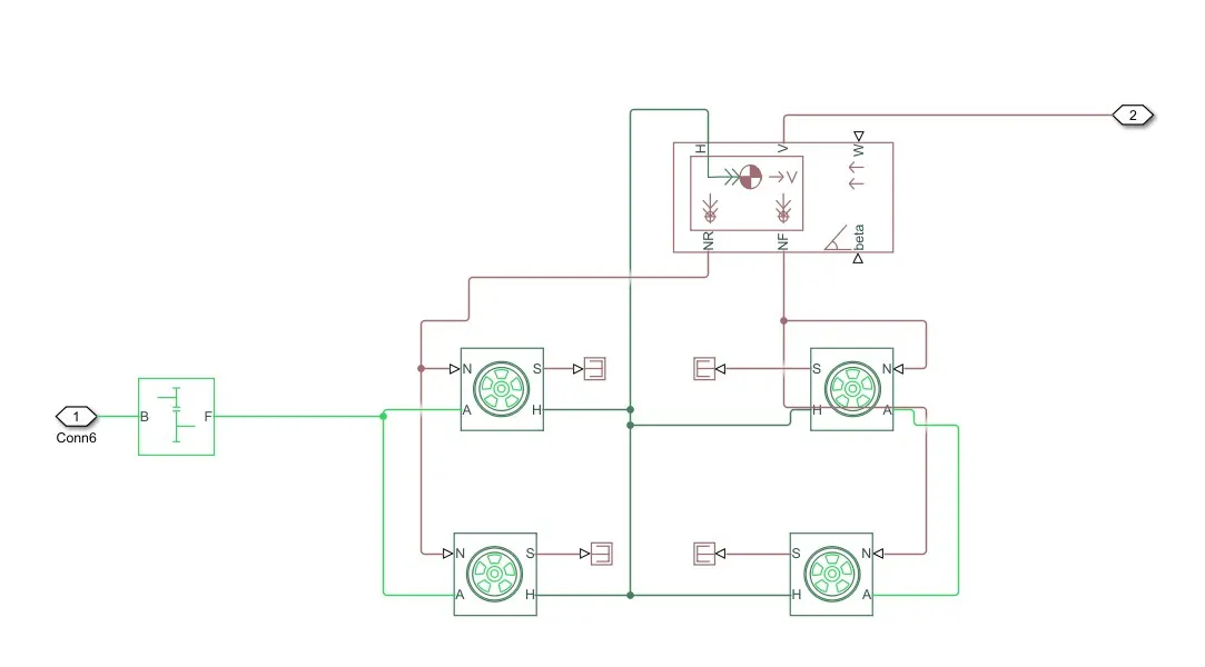
It is the most fundamental part of the system because all the forces that would be calculated to select the motor power based on it.
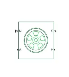
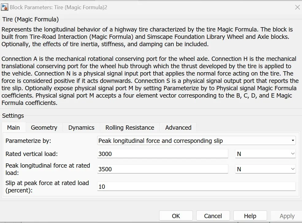
Tire block :
Vehicle Body :
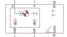
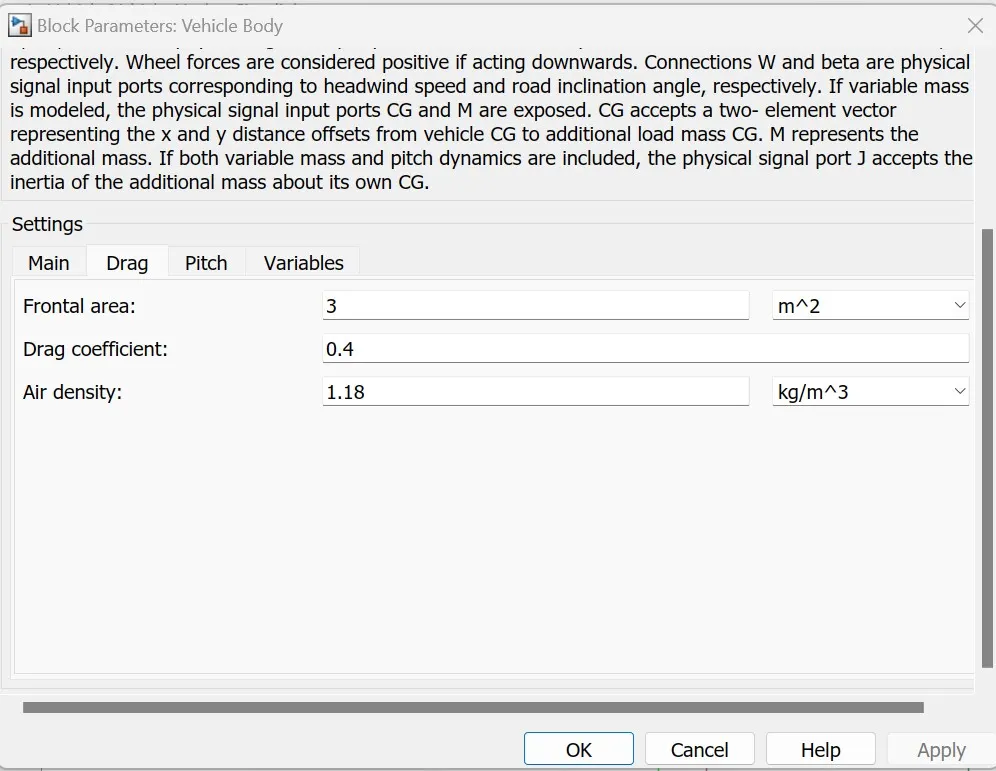
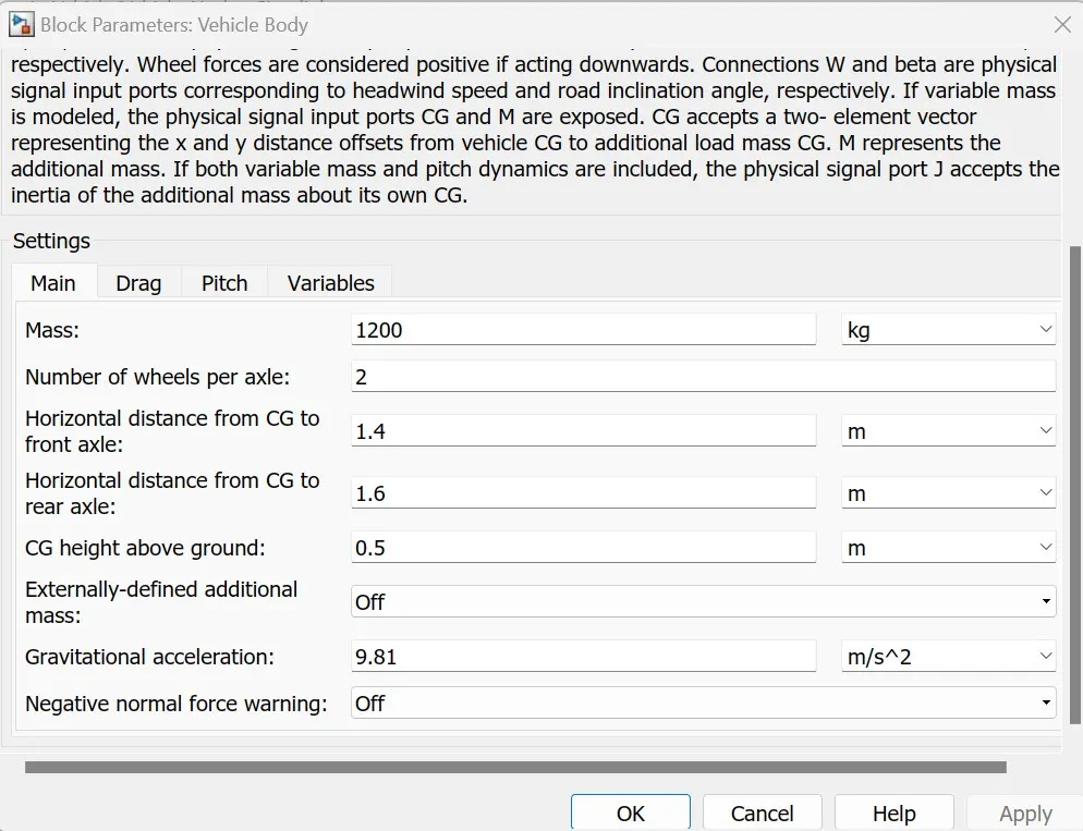
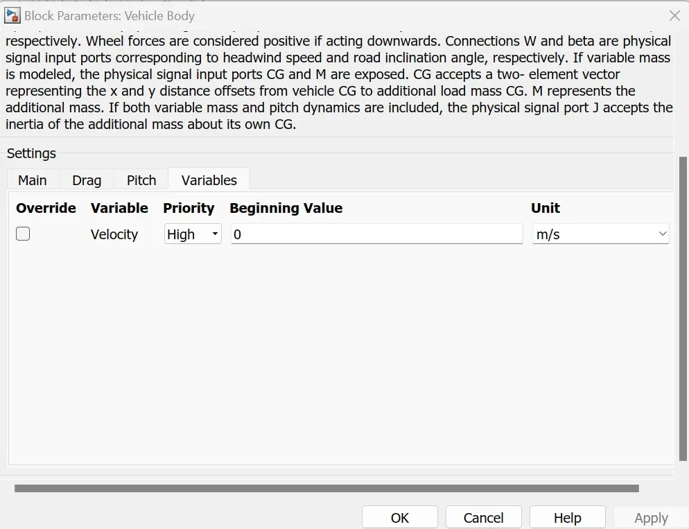
This block will facilitate us to realise the vehicle select the physical parameters of the vehicle as vehicle weight,wheel of the vehicle per axle,Distance between two axles of the car body,Car's hight from the ground,Air drag coefficient,Gravitational Acceleration & other variables. We can configure vehicle body as we wanted by just changing this values.
We have to provide following inputs to this block:
1)Normal force on front wheel (NF)
2)Normal force on rear wheel (NR)
3)Windage force on vehicle body
4)Hub (through all the wheels are connected)
5)Inclination angle of the road with reference (Grade)
Output of the Block:
Vehicle Velocity in ( Desired Unit)
Simple Gear:
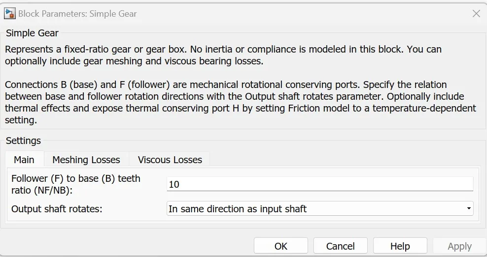
This Part of the mechanical system will convert the Motor output rotational foece into desired rpm needed by the vehicle.It will also help to achieve the trade off between Speed & Torque of the vehicle.
Electrical System :
Electrical Suystem is a powering system which will give rotational mechanical output to the vehicle.It includes the power converter which will produce the voltage from which we could able to control the vehicle as we want.Also the power converter will convert back the mechanical power into electrical power feeding back to the system during the brakig operation.
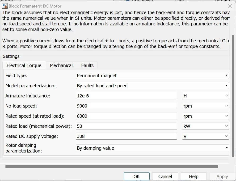
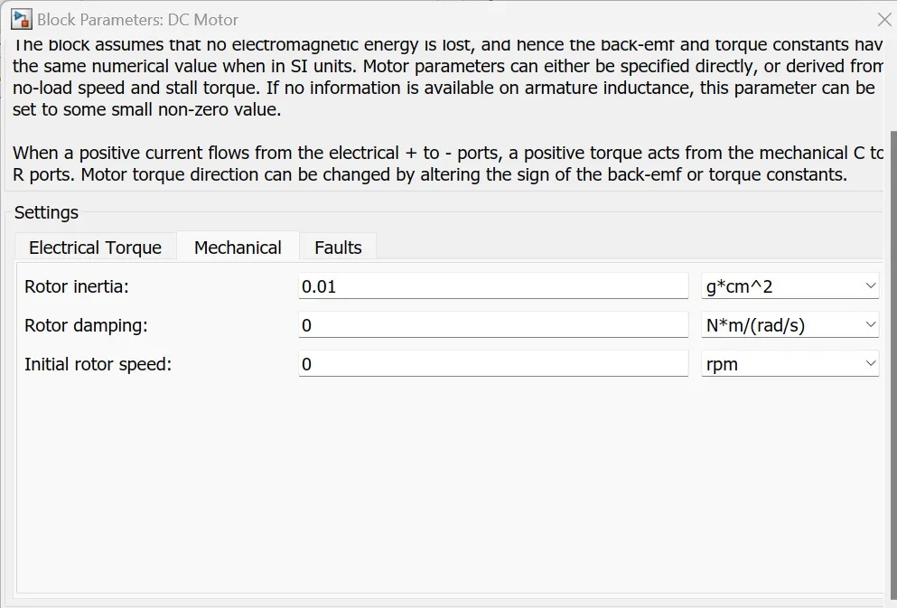
DC Motor:
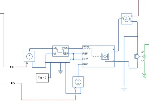
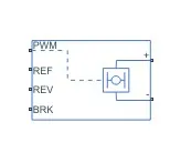
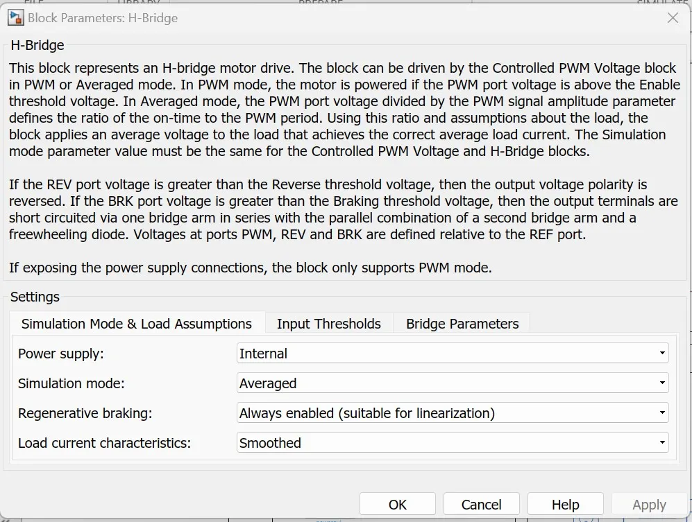
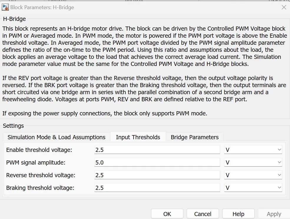
H Bridge Converter :
It is the main component Which converts the Electrical power required as same as demanded by the motor. The power conversion command to the bridge swithches will be generated by the controller & this controller will generate this signal based on the Driver's Input.This same block is also responsible for converting the mechanical power into electrical power during the braking of the vehicle.
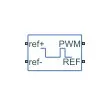
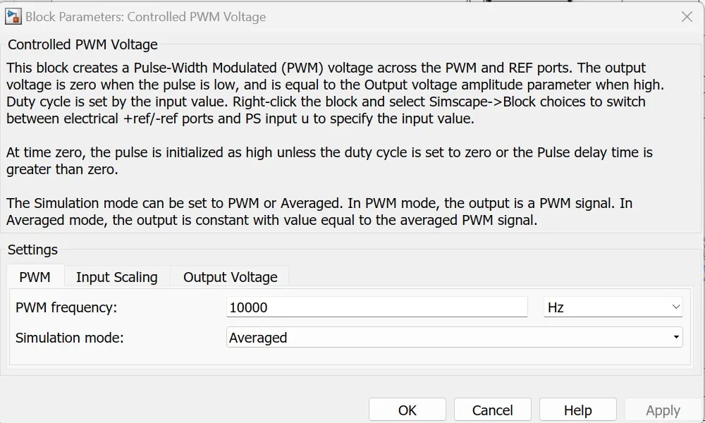
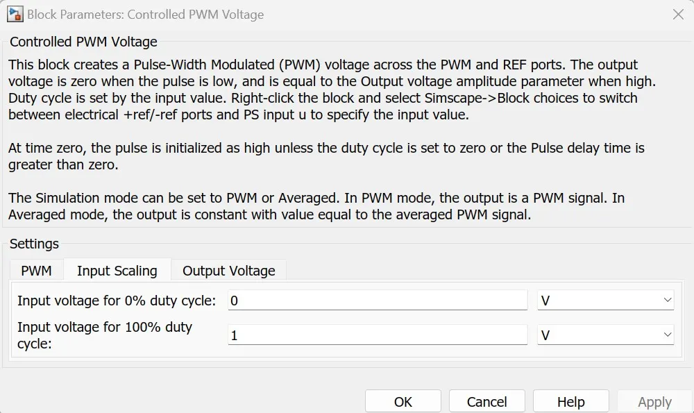
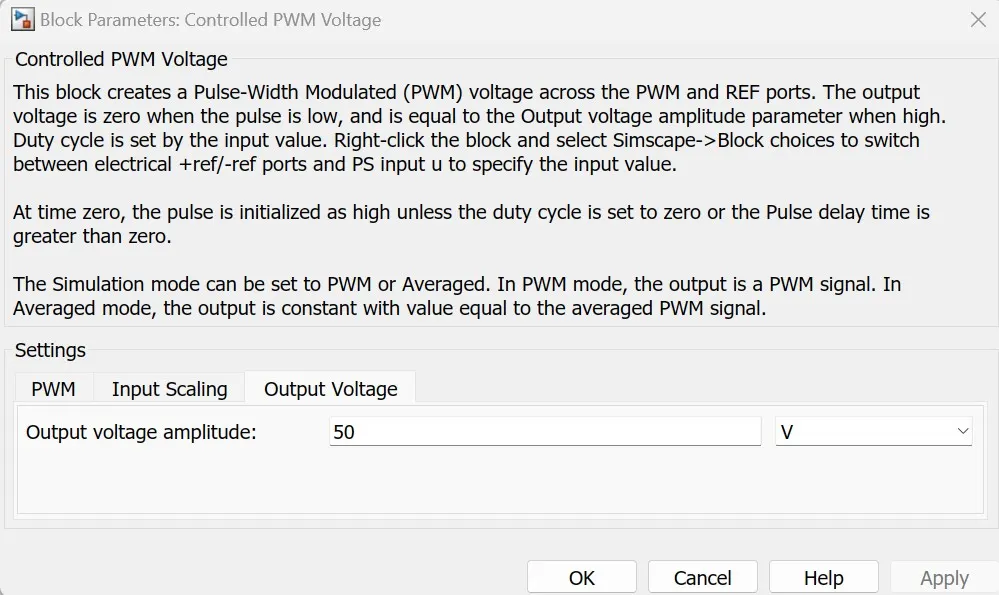
PWM Controlled Voltage:
This is the block which will generate the switching sequence for the switches located in the H bridge converter.The output of this block is regulated DC Voltae.It has also provision of braking voltage generation signal input.
Controlled Voltage Source:
This controlled voltage source is used for the input of PWM voltage generator. The controlled signal given by the PID output will given ti this block & it will generate the commands for the controlled voltage source.
This block has been used for the acceleration command & braking too.
Solver Block:
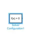
Solver block will help us to run the simulation smoothly & without generating any error.
Electrical Referance :
Electrical referance is used to detact the referance voltage for each block used in electrical system.
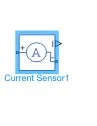
Current Sensor :
It will detact the DC motor output current & accordinlgy give signal to battery system to discharge.
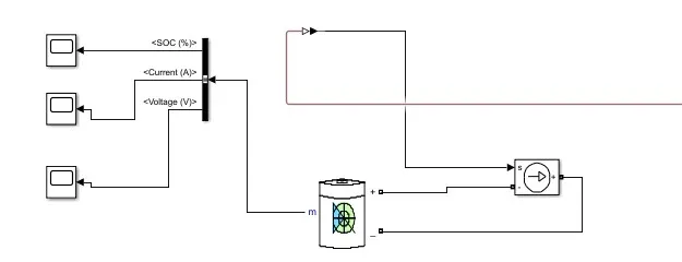
Battery System:
it is the main powering source of the electric vehicle. The vehiclw will get the electric power from the rechargable battery mounted on the vehicle body.it will contain the following blocks.
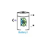
Battery :
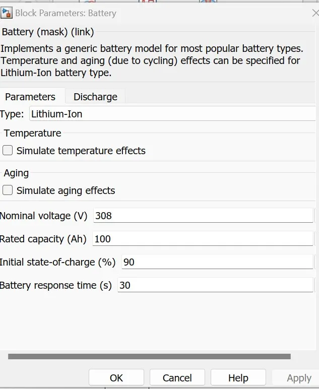
It is Lithium ion Battery with following configuration. This block has inbuilt capabilities to show the Battery SOC.
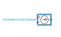
Controlled Current Sensor :
This will give input to discharge the battery as the controller needs power.
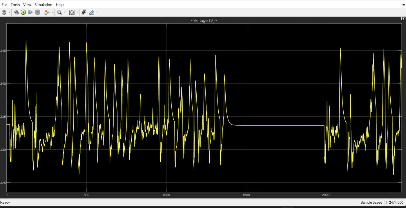
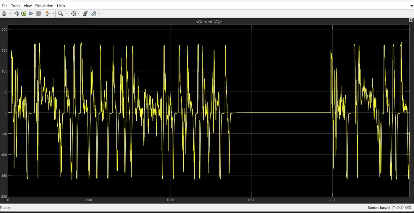
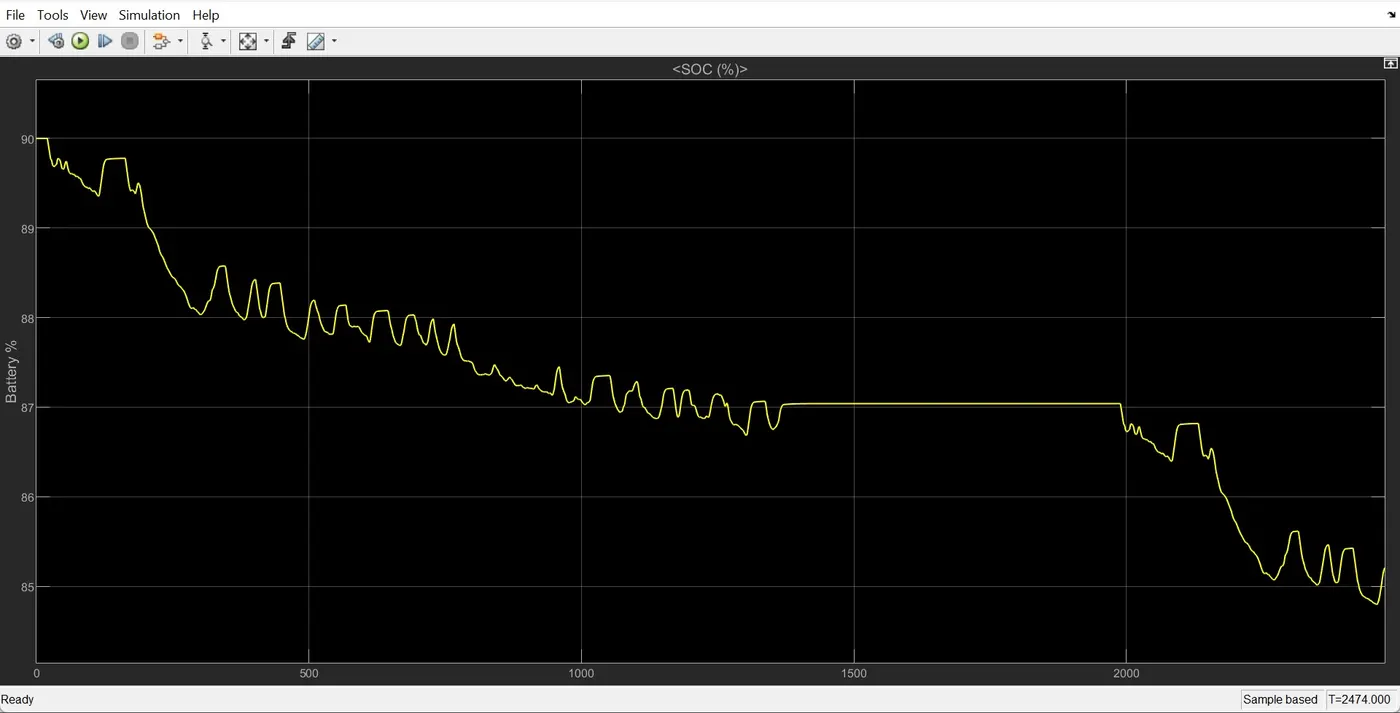
The battery system also has SOC,Voltage & current output port. These are real time output data of the system.It could be also used in calculating the power consumption of the system. As our vehicle is propelling forward the SOC will be decrasing gradually.
Control System as a (Longitudinal Driver):
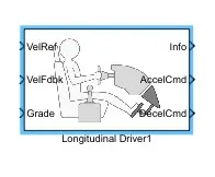
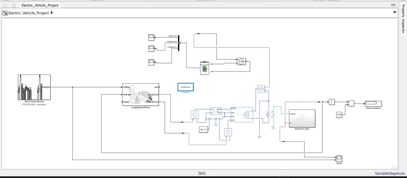
This is very important part of the Electric vehicle. In other words we can say that this is the mind of the electrical vehicle this block is responsible for the generation of the signal of Acceleration connand & deceleration too.All the command will be processed here & based on the error signal the controller input will be prooduced by this system.it includes PID controller , Drive cycle, Saturation block,PowerGui block.Here the output of the vehicle body will be given back to the PID controller to generate the error signal.The drive cycle will give input as a meter/second & the error signal will be generated according to their difference.The saturation block will bound the acceleration & braking inputs in limit for the control signal input.
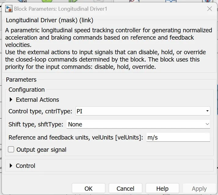
The default configuration of the block is PI controller which generates the the Kp & kI gains which would give the most equal output as the input.The powertrain block set library has some of the most delibrate blocks which can be very useful to design the vehicle & this longitudinal driver block is one of them.
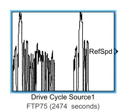
Drive Cycle :
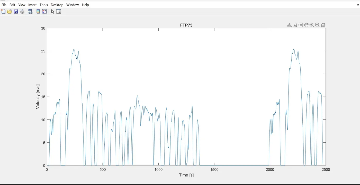
Drive cycle is a set of speed data, which you want to test on the vehicle.It could be normal vehicle's speed in traffic to Wide open throttle condition.I have taken here the FTP75 drive cycle to test the vehicle.
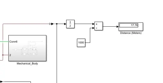
Distance Calculation :
The output of the vehicle block would be in the form of speed, So if we want to calculate the distance than simply we have to integrate it once.
The final configuration of the simulink model will be look like as below:
Result :
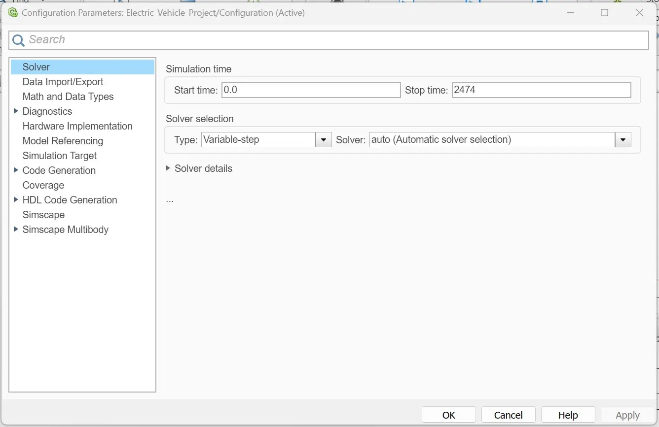
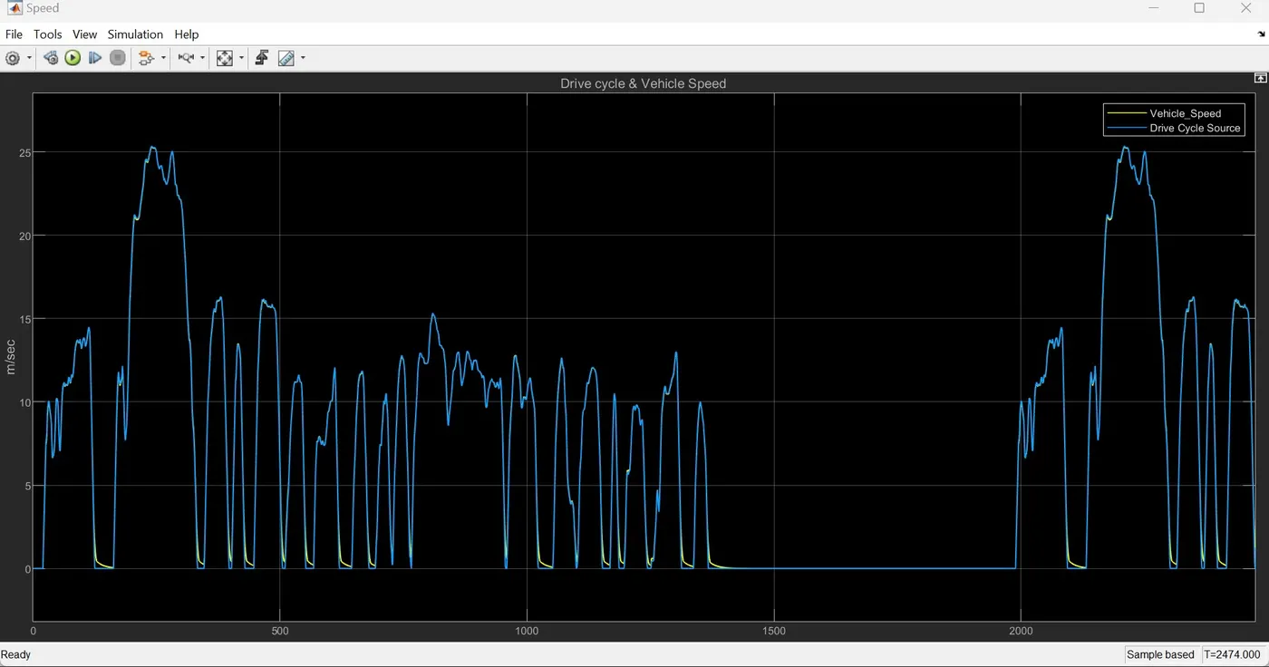
I have run the model for default seconds for the FTP75 drive cycle (2474 Seconds). Also the Solver configuration is VariablestepAuto.
Speed Plot :
Battery Voltage :
Battery Current :
Battery SOC :
Conclusion :
The vehicle model's Longitudinal controller works accurately & the vehicle speed is very near to the referance input given.This model gives us idea about EV's working as a component level & system level too.Also We can do more test on it like extreme diverse conditions (WOT).
The longitudinal driver is a kind of complete block but if one has to understand & design the Vehicle from scratch than he/she has to work on the mathematical model & find its control system & PID gains.