Week-6 Challenge: EV Drivetrain
Question 1 Solution :
Power converter circuit :
A power converter is an electrical circuit that changes the electric energy from one form into the desired form optimized for the specific load.
As in our Electric Vehicle application Power required by it is time varying i.e. the amount of power needed to propell vehicle is continuously varying by air drag,hill effect and
all other aspects. So we have to vary the power output of motor by demand and here the power converter circuit comes in picture.Also the auxilary accessories have differrent power rattings.
Here, below I have listed some prime converters which are used in EV & HEVs.
1) If we are using DC motor than DC voltages can be varied with the help of DC-DC converter called Chopper.which step UP/DOWN s the voltage levels as requriement.It comes in picture when lesser amount of voltages
needed for propulsoion.
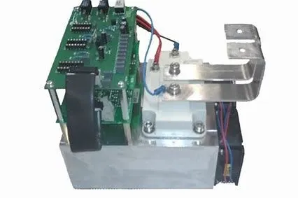
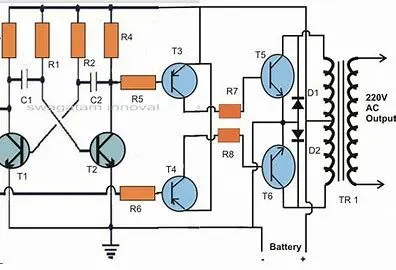
2)DC to AC Power conversion done with the help of Inverter circuit. If our Main traction Motor is 3 Ph. Induction motor than it needs fully controlled Inverters with High frequency Switches which is done by it.
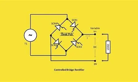
3)AC to DC ( Rectifier ) Power conversion is by it. Whenever Regenerative braking phenomena occurs the kinetic energy of the motor is converted into AC power with the help of generator action which is stored again back ti battery by AC to DC conversion.
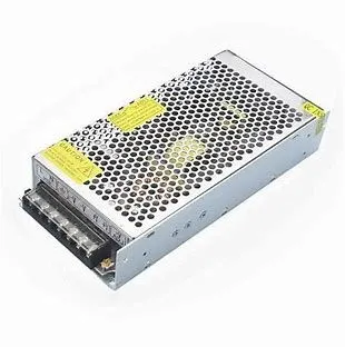
4)SMPS(Switch mode Power supply) : This converter provide constant DC 5,12,24 volts for control signals used in Drive & PLC cards of the system.It gives supply to different car accessories , control signals ,sensors .
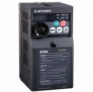
5)Veriable Frequency Drive(VFD) : It has 3 phase AC Input and output will be generated accordingly as per user commands input.It has more flexibility than conventional resistive control strategy. Also it has more efficiency & power saving abilities.
Question 2 Solution :
As per given data from problem ,
Armature Current (Ia) = 400 A
Rated Armature Voltages = 72 Volts
Armature Resistance (Ra) = 0.5 Ohms
K*Phi = 0.7 Volts seconds
Chopper Switching Frequency = 400 Hz
Duty cycle = 70 %
First finding the Voltages of Battery (V avg) at steady state point = Duty cycle * V(battery)
= 0.7 * 72
= 50.4 Volts ...............(1)
as per motor speed equation Eb = k*phi*w
w = Eb/k*phi
= 50.4/0.7
= 72 rotation per second
Now putting this speed in the given torque equation Tv = 24.7 + (0.0051)w^2
Tss = 24.7 + (0.0051)(72)^2
= 24.7 + (0.0051)(5184)
= 24.7 + 26.4384
= 51.1384 N-m .............(2)
Putting this Torque in standard speed equation,
Wn = V(avg)/k*phi - [Ra/(k*phi)^2]*T
= 50.4/0.7 - [0.5/(0.7)^2]*51.1384
= 72 - 52.1820
= 19.818 rps
Question 3 Solution :
If we think llike previous question's analogy to build the model We need to first obtain the plot characteristics which is varying in time nature I am going to use previous question's data as a reference.So to get this
I am going to vary the parameters in following sequesnce.
[ Duty cycle > V (battery) > Rotation per Seconds > Torque > speed plot ]
First we will vary the duty cycle from 0 to 100 %, from which we will get time varient battery Input Voltages by which we will get the torque accordingly.
This torque we will put into Speed equation of Wn= V/k*phi - [Ra/(k*phi)^2]*T in rps
I simulated the model as above strategy but this strategy as below
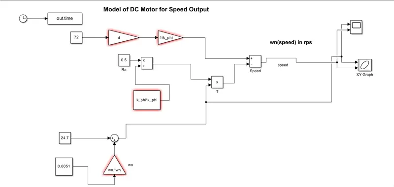
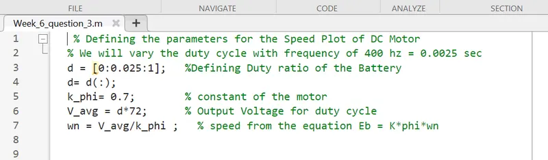
but I didn't get desired Outputs for speed. So by attending one on one Session I got the idea about taking Torque as an Ramp Input and make all other quantities to be constant.
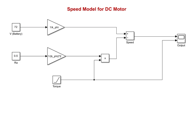
I have taken the equation parameters as below,
V(battery) = 72 volts
k_phi =0.7 volts seconds
Ra(Armature Resistance) = 0.5 Ohms
T (Torque) = Ramp input
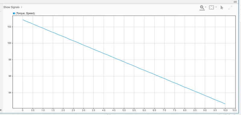
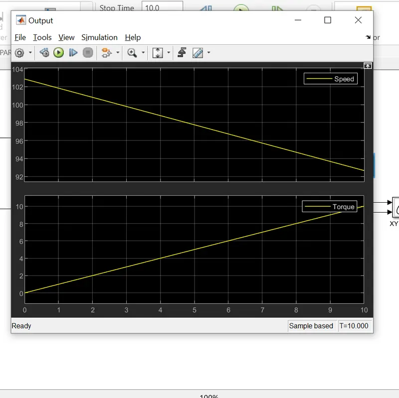
The model is shown as below and underneath it I have shown the Results for Differnt Torque ( slopes )

For Torque slpoe = 1
For Torque Slope = 2
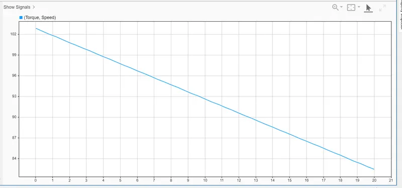
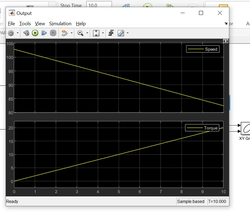
We can say by analyzing the output plots that by increasing the torque variaton with respect time It doen't affet the initial speed.
Question 4 Solution :
First of all I would like to admit that this is the one of the best article I've read of all time.Here the Auther has explained all the facts which influences on selecting suitable Drive
for EV Applications, their advantages & disadvantages ,which would be costly ?, Who has complex control strategy & so on.
Every Engine is different in terms of design , application , User demand So one can not say that this is an ideal Engine for any vehicle.Also Contactor & Brushed DC motor has been replaced by Modulating Inverters,BLDC Motor & Induction motor.
Here, more in detail He explained the difference between BLDC Motor & Induction Motor.BLDC having 3 coils which energies one by one & rotor (which is permanent magnet) tries to catch that stator virtual magnet after reaching that position sequential next coil is energies by
controller and rotor rotates that way.To control BLDC & made constant Torque We have to put sequencial coil energising strategy.
Unlike BLDC 3 phase Induction Motor can be directly connected to the Utility 3 phase power. The stator have 3 coils distributed & it generates Rotating magnetic field.Rotor which has short-circuited Bars at end rings, along with length cuts it & Voltage inducing
it according to speed difference between RMF and physical Rotor itself.Rotor continuesly tries to catch the Stator RMF and nullify the difference in RMF and Rotor itself.With Utility Power they have limited starting Torque.To control Speed We have to introduce inverter
at supply of Motor which provides Variable frequency supply & thereby variable speed.
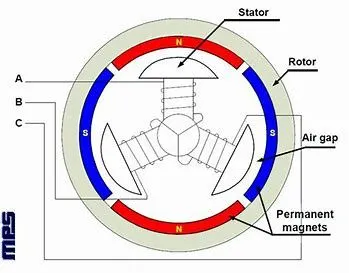
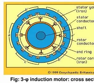
Key Diferernce between BLDC and 3 ph. IM are as follow...
1) Their Rotor structure & Inverter control strategy.
2) BLDC has no control over Magnetic field stength (B) so it would not so efficient at high and low peak demands of Torque.Contrary to it 3 ph Induction Motors that kind of control with V/f strategy.
3) Induction motor is less constlier as Parmanent magnets are costly,Also ferromagnetic material in vicinity to BLDC affects its performance.
4) Induction Motors have more complex control laws and not easy to attain stability.
Conclusion:
In fucture with Increase in demand of High performance of EVs Both of the motor will likely to be combined as they have more similar hardware arrangements.till than IM drive will dominate in pure EVs and
BLDC in HEVs.