Week-7 Challenge: DC Motor Control
Question 1 Solution :
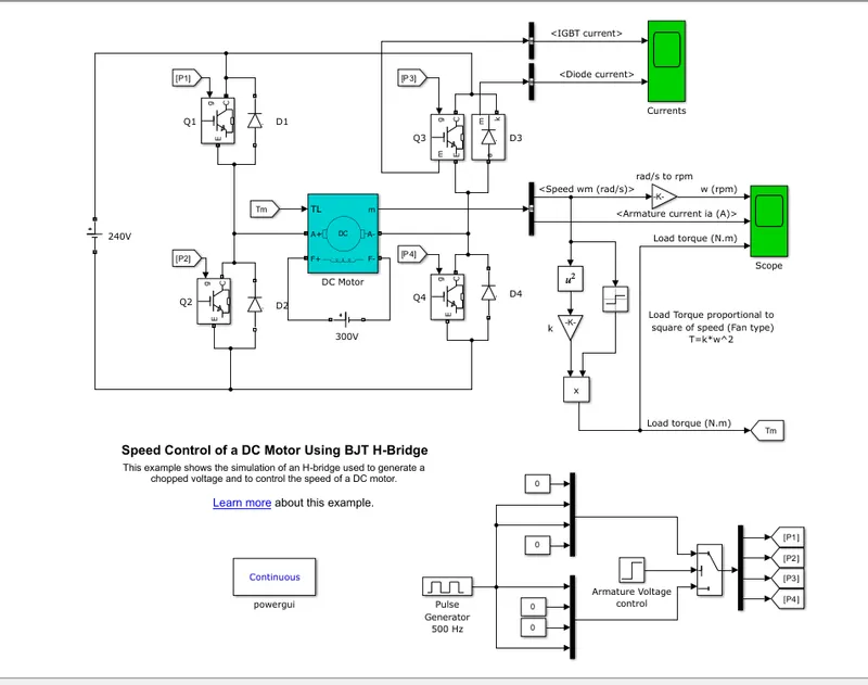
As per asked to analyze the Model of 'Speed control of a DC motor using BJT H-bridge.' I went to the MATLAB official Website & got the link for Model.
By pasting the link in MATLAB offline trial version the simulink Model pop uped as below.
(A). About Model :
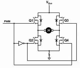
This is the simulation of H bridge Inverter , its simplified circuit version is shown as per above figure. As we know the mechanical commutator converts applied DC voltages into AC
to the Armature of Motor. Instead of that We are providing AC input with the help of H-Bridge Inverter with full control of switching.
Here Separately excited DC motor is used , i.e. for Field Excitation separate DC voltage is given of 300 V. It has not any kind of control over field voltages so we can say that the model is
constant field model.Q1,Q2,Q3,Q4 are controlled switches with P1,P2,P3,P4 Controlling signals.Pulse generator creates control strategy for switching of 500 Hz.The simulation is done for 1 Second.
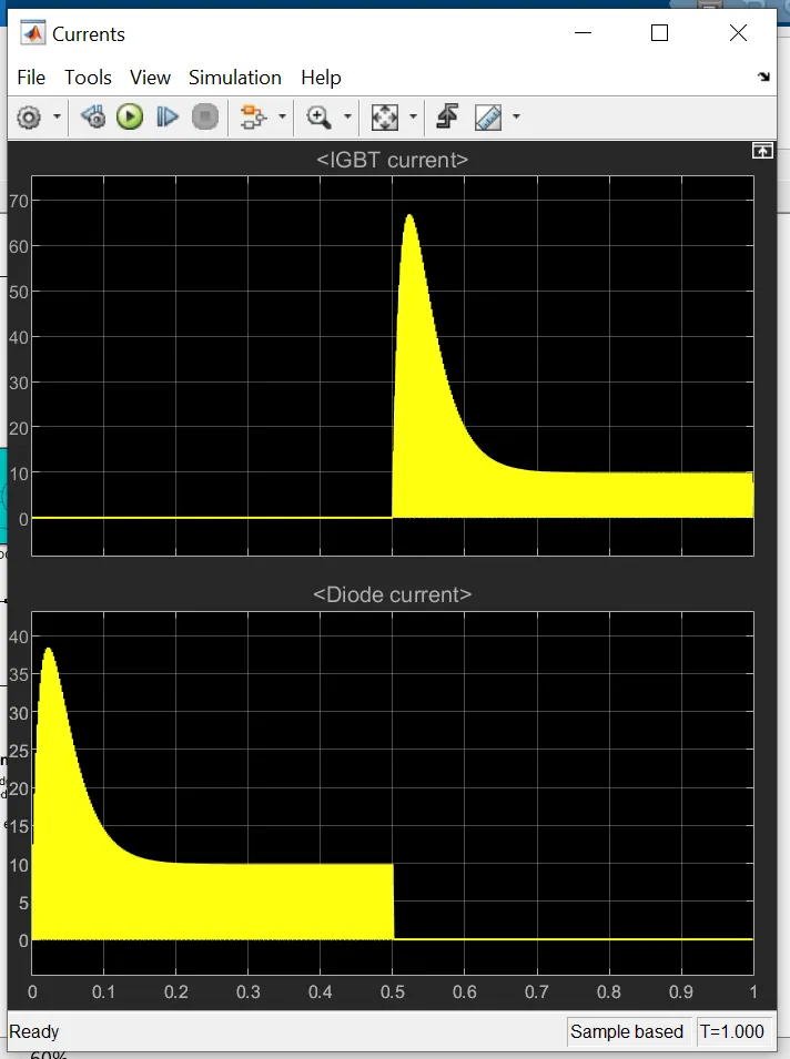
For first half cycle till 0.5 seconds switch Q1 & Q4 are in on state ,supplying the positive voltage to motor & Q3 and Q2 are in on state for negative half of cycle supplying negative voltages fornext 0.5 second.
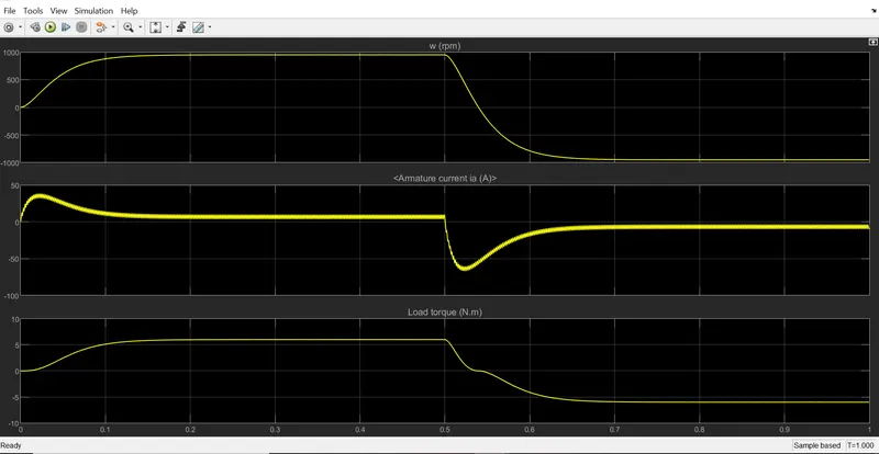
So by this switching sequence AC can be feeded to Motor with DC Source.But by seeing the Torque plot we can say that it would be in Positive & Negstive fluctuating.So our Motor shaft will be Rotate in Positive & negative direction.
(B). Armature Current Shoot-up :
To understand this shoot up lets first see the Armature current & Back Emf relation given by
Ia = Vt - Eb/(Ra+La).................................................(1) &
Eb = K*ph*W .......................................................(2)
where, Ia = Armature current
Vt = Armature Terminal voltages
Eb = Back Emf of the Motor
Ra = Armature resistance of the motor
La = Armature circuit Inductance
ph = Field flux
W = Speed of the motor
K = Constant
When the Motor is at standstill the speed of the motor would be Zero. So from equation (2) the Eb would be zero. So The Armature current is only restricted by Armature Resistance Ra (ignoring La for better understanding).
This can be related by equation no (1). So the Current jumps from 0 to V/Ra value in very less time.After Motor starts , speed (w) increases and also Back EMF comes into picture and tries to restrict the (Ia). So the Motor speed
Increases the Armature current decreases & when the motor attains steady speed the armature current (Ia) becomes constant. This relation is also can be confirmed by following graph plot.
(C). Comparing H-Bridge with Four Quadrant-Chopper (D7) block :
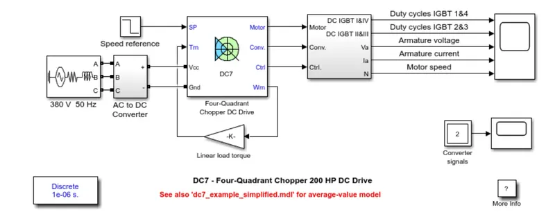
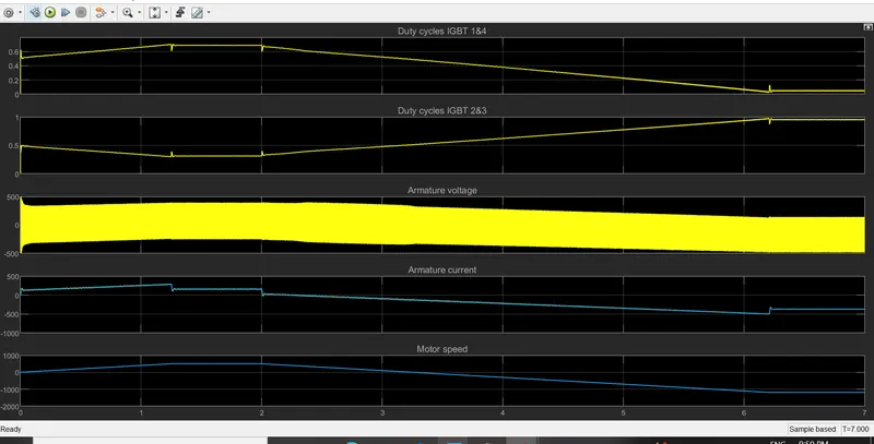
The Four quadrant chopper (D7) block is simple in design also , switching sequence is easy to configure comapared to conventional Power H bridge Inverter.Here in this model of DC7 block they are using AC voltages as a source than it convertes in to DC to feed chopper Input. also it takes reference Speed input throgh Current control feedback to get more precise control over motor.
Though it does not have that initial Armature current control spike,It can be seen in graph plot.
Question 2 Solution :
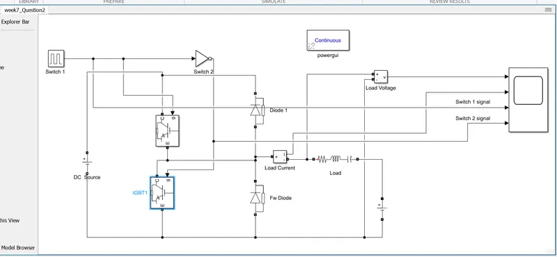
The 2 quadrant chopper name itself indicates it operates in 1st & 2nd quadrant of Voltage vs Current plane.The circuit arrangement is such a type in which the voltages across the load remains Positive
but the current goes from positive to negative.I have used IGBT as switches and annoted as Q1 and Q2. FwD is free wheeling diode in off state of both switches. The NOTE gate used here to ensure both Switch does not
turn of simultaneously.The load is choosen as RLC and the DC source connected beside load acts as Source in freewheeling state.
The model for 2 quadrant chopper is as below shown..
The output waveforms for the DC source voltage=24 volts & store voltage in inductor as 12 volts is shown below.Here I have taken total time as 0.1 seconds with 50% of On state pulse.
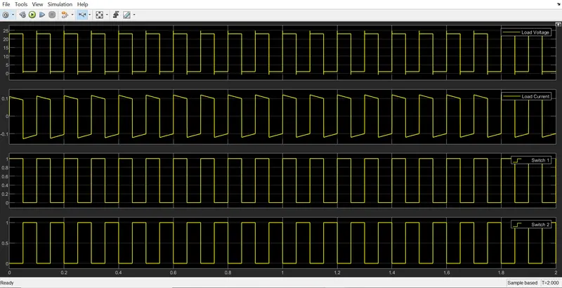
From the waveforms the working of the circuit can be comprehended as when switch(Q1) turned on by pulse signal, Source voltages appears across the load. When switch (Q2) turns on source at RLC type load appers across load. Here due to unavailability
of Separate Inductive tyoe of load the freewheeling state of diode FWD & D1 conducting states can't seen in the plots.otherwise when the switch (Q1) turns off the freewheeling doide conducts current throgh load till Swich (Q2) turns on & Diode (D1)
conducts after switch (Q2) turns off till switch (Q1) starts conducting.
We are getting the current in both positive & negative polarity with load voltage at same positive polarity.If we relate it with EV Application analogy than it is kind of state in which the power developed by Vehicle inertia utilized
to stall the Vehicle at the time of braking without incorporating the Power source in the circuit.
Question 3 Solution :
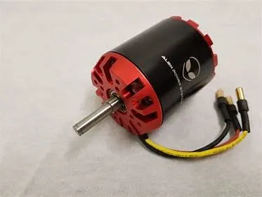
BLDC (Brushless DC Motor) : As the name says itself, It is doesn't have Carbon Brushes which conventional DC Motor has.To understand the BLDC operation lets first understand the DC Motor operation in brief.
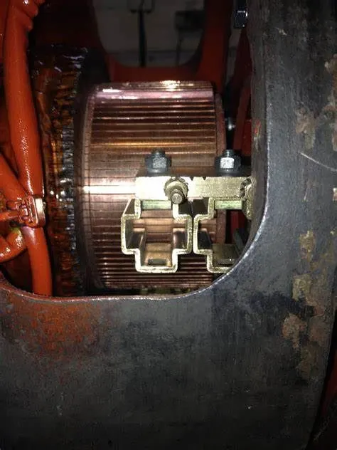
As seen above the conventional DC motor uses Brushes to collect the current from external DC Source & supplies it to Armature of Motor.In this operation Brushes get damaged by wear & tear losses.This is main drawback in this kind of motor.
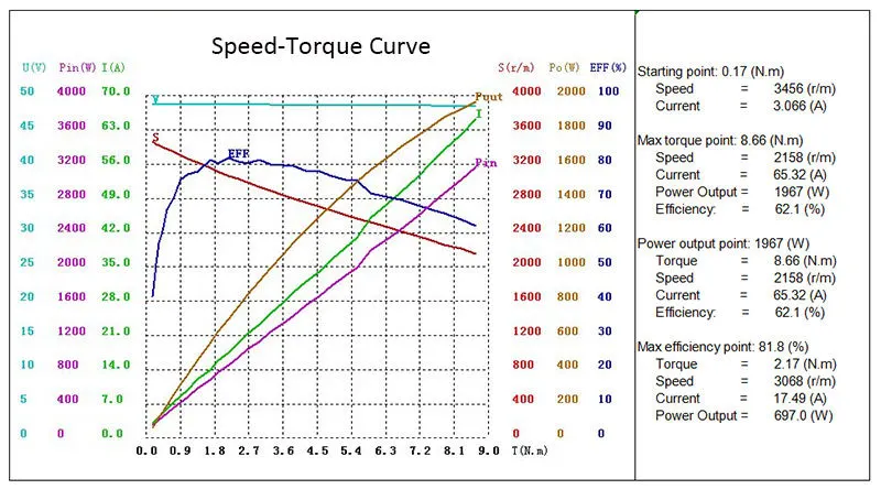
BLDC motor is entirely different than DC motor.Due to its Output Speed Torque nature similar to DC motor it called as BLDC motor.It uses pairs of permanent manet instead of Electromagnet.2 out of 3 windings are energies simultaneously with
different pole generated on them. One coil attaracts the Rotor permanent magnet & another repells it. Which creates double torque to be generated as shown below.
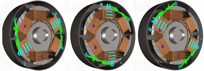
When the Rotor with permanent magnet tries to catch that , before it does coil next to that it energised.The Magnet again tries to catch ploe of electromagnet and it rotates by this way.All the time Rotor with permanent magnet tries to catch
that electromagnet but it doesn't catch it & we get our rotor to be in motion by this way.To make this Constant rotation with constant torque we need to apply signal in sequence to energise coils to make this implementation.So the stator coils have
controller wchich does it.One has to design the switching sequence to achieve it.
By its construction as Rotor inside or Outside the BLDC motor has 2 types:
1) Hub Motor :
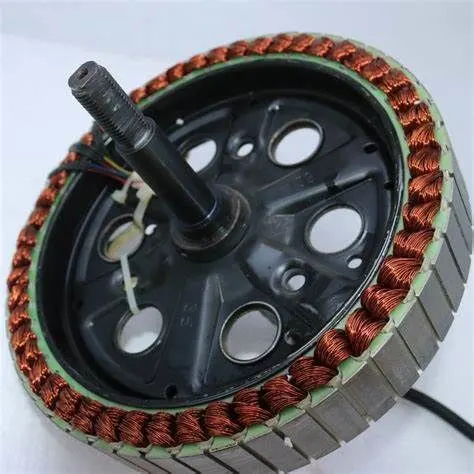
Hub Motor has Permanent Magnet inside and coils arrangement outside
2) Outer Rotor Motor :
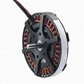
This kind of motor has Permanent Rotor Outside & the coils inside.Outer rotor motor has comparitively higher torque generation comapared to Hub motor.