Photo Realistic Rendering
DESIGN OF CHOPPER USING SOLIDWORKS
OBJECTIVE:
To learn all the tools used in designing the chopper.
INTRODUCTION:
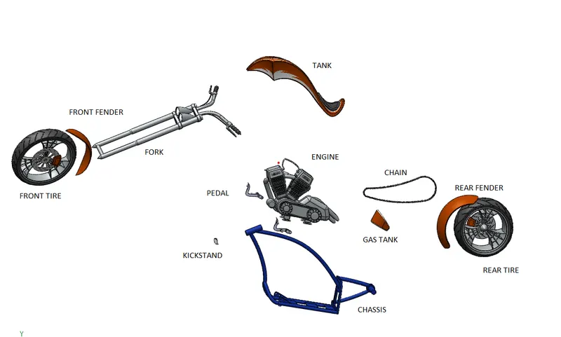
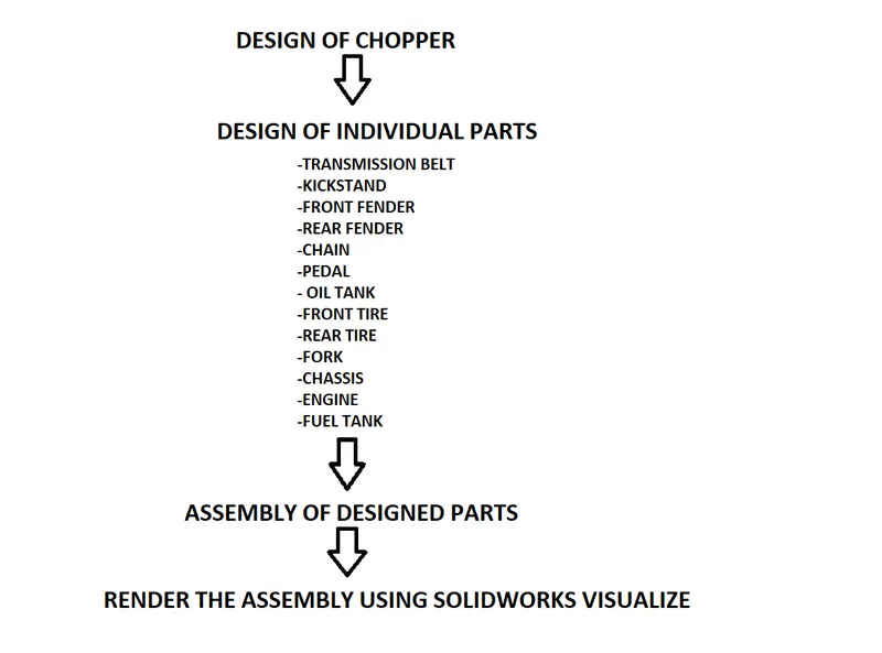
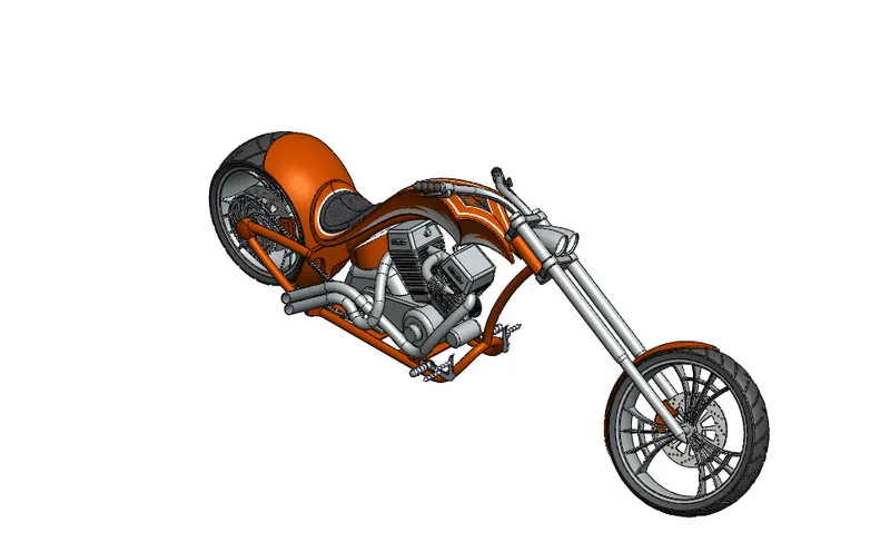
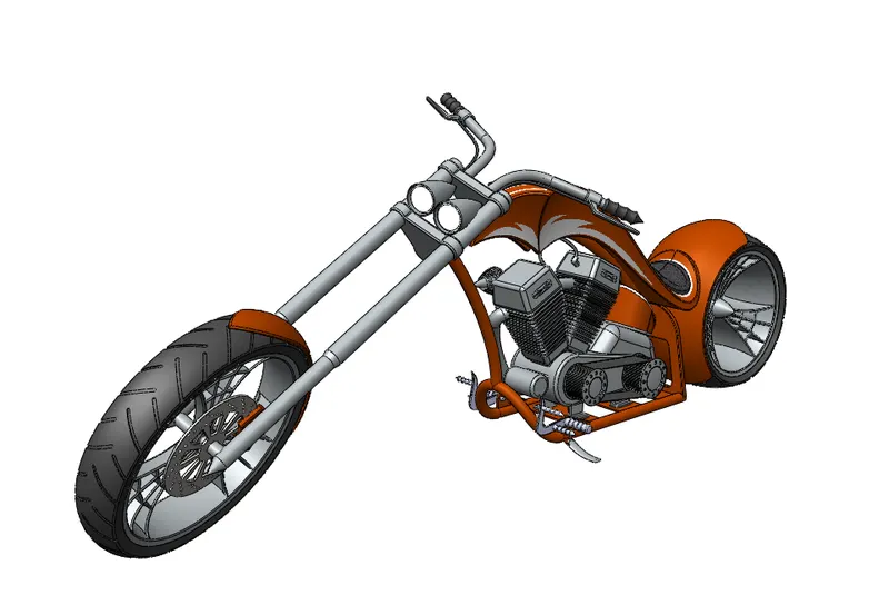
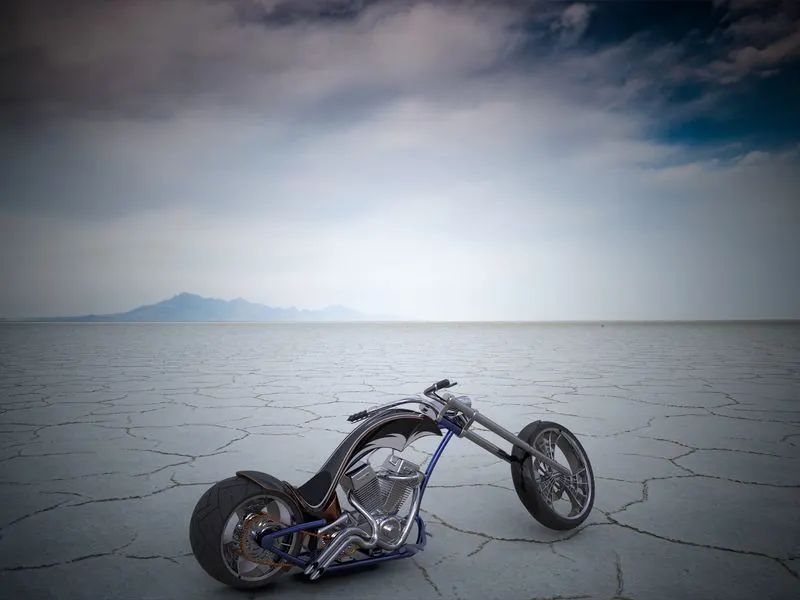
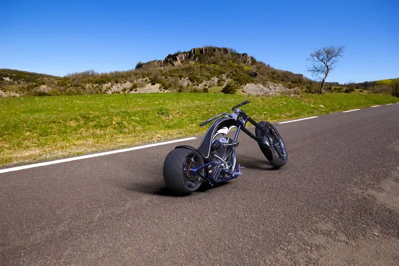
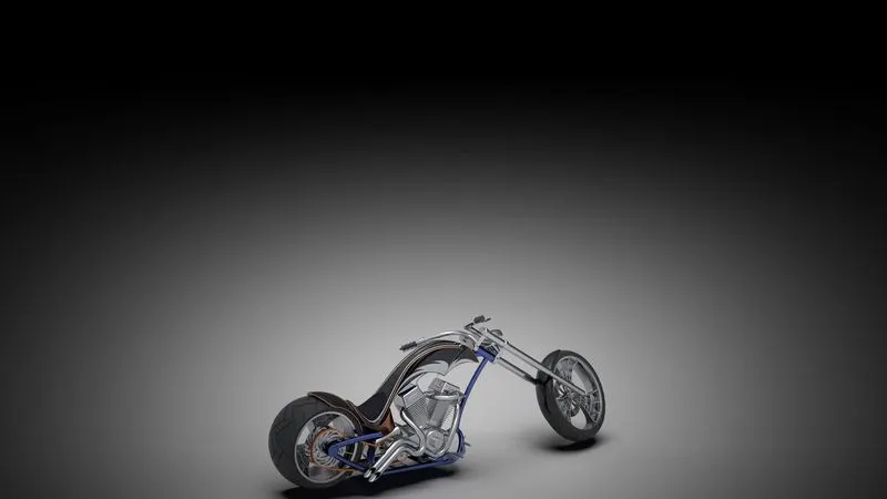
In this project we will learn how to use different tools in Solidworks to create parts for the chopper . First we take individual parts and design it. Finally they are assembled together to form a complete part. The assembled part is then placed in an environment and it is then rendered to create a rendered picture.
DESIGN METHODOLOGY:
DESCRIPTION:
Tools and features used:
1) Line tool: Line tool is used for drawing lines on the sketch and references.
2) Circle: Circle is used for drawing circles in a sketch.
3) Spline tool: Spline tool is used for creating curved lines by giving it a weight values.
4) Rectangle: This tool is used for creating a rectangle or a parrellogram using different methods.
5) Arc tool: Its is used in creating a arc in a sketch and it has different types.
6) Ellipse: This tool is used for creating ellipse, parabloa and conic.
7) Slot tool: This tool is used for creating slots quicker and as a complete one.
8) Polygon: This tool is used for creating polygon by giving parameters.
9) Sketch fillet: This tool is used for creating fillets on a sketch .
10) Smart dimension: This tool is ued for creating dimensions between two entities.
11) Trim entities: This tool is used for cutting excess lines .
12) Extend entities:This tool is used for extending a line.
13) Convert entities: This tool is used for converting a edge or a outline of a feature to a sketch.
14) Intersection curves: This tool is used for creating curves that is intersected by two other lines or curves at different planes.
15) Offset entities: This tool is used for creating a offset sketch or line based on other sketches .
16) Mirror entities: This tool is used for creating mirriored sketches with respect to a reference line or a plane.
17) Linear sketch pattern/ Circular sketch pattern: This tool is used for creating mutiple sketches of the same by taking references of a straight path or a circular sketch.
18) Composite curve: This tool is used for combining curves and lines to create a single sketch .
19) Point: This tool is used to create a point .
20) Split: This is used to cut a solid body using a line .
21) Combine feature : This feature is used for creating combined bodies with existing other bodies that intersect.
22) Extruded Boss/Base: This is used for extruding a closed sketch or a contour of a sketch.
23) Revolved Boss/Base: This feature is used for creating a revolved body based on axis.
24) Swept Boss/Base: This feature is used for creating swept body which consists of a guide curve and asketch at the end of the curve.
25) Lofted Boss/Base: This feature is used for creating a lofted part which has different sketches at each end of the curve or a line.
26) Extruded cut: This feature is used for cutting a part of a extruded body based on a sketch.
27) Revolved cut: This feature is used to cut parts in a body with axis
28) Fillet: This feature is used to round off edges.
29) Chamfer: This feature is used for creating chamfers with different parameters.
30) Linear pattern: This feature is used for creating multiple bodies or features with reference to a line.
31) Circular pattern: This is used for creating multiple bodies based on a circular path.
32) Curve driven pattern: This feature helps in creating multiple bodies or features based a curve.
33) Mirror: This feature is used for creating mirrored parts or bodies based on a reference plane or line.
34) Draft: This feature is used for creating a drafted body with only side smaller or bigger than other.
35) Shell: This feature is used for creating shelled bodies of a solid part with a feature to remove a face.
36) Reference Plane/Axis/Co ordinate system/Point: These features are used for creating Planes, Axis, Co ordiante System and a point for reference.
37) Projected curves: This feature is used for creating a curve based on two other curves. The new curve is created where the parent curves intersect.
38) Extruded surface: This feature is used for extruding asurface with closed sketch.
39) Swept surface: This feature is used for creating a swept surface with a guide line and a sketch.
40) Lofted surface: This feature is used to create surface base don two or more profiles and a guide curve.
41) Boundary surface: This feature is used to create surface using planes curves and lines.
42) Surface knit: This feature is used to combine two or more faces or features into one. It can also use be for filling the bodies.
43) Surface trim: This feature is used to cut parts on a suface using curve or a line.
44) Dome : This feature is used to create dome shape on a given surface for a required radius.
45) Appearance: This tool is used for applying a material to a part or a certain face.
46) Sketch picture: This feature is used to insert a refernce picture of the part . This helps in tracing and approximating dimensions.
TOOLS USED:
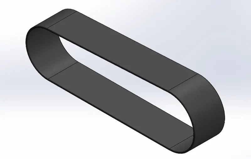
TRANSMISSION BELT
Sketch tools, Extrude Boss/Base, Fillet and Appearance.
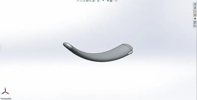
KICKSTAND
Sketch tools, Loft, Dome, Cut extrude, Split, Boss extrude, Fillet and Apperance.
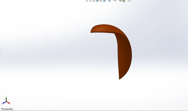
FRONT FENDER
Sketch tools, Revolve, Split, Fillet and Apperance.
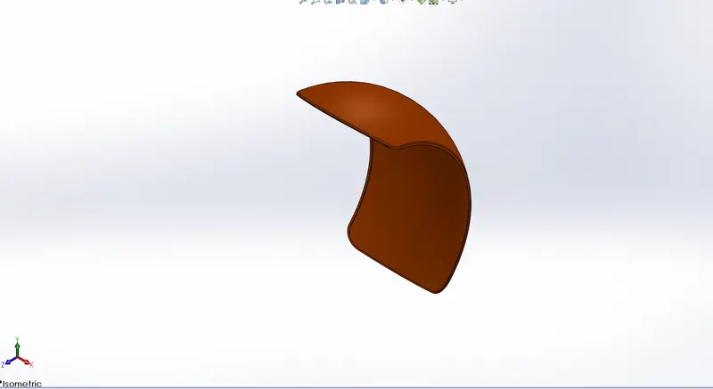
REAR FENDER
Sketch tools, Revolve, Split, Fillet, Shell and Apperance.
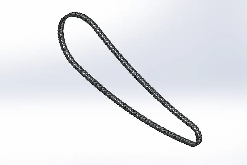
CHAIN
Sketch tools, Blocks, Boss extrude, Fillet, Curve pattern, Mirror and Apperance.
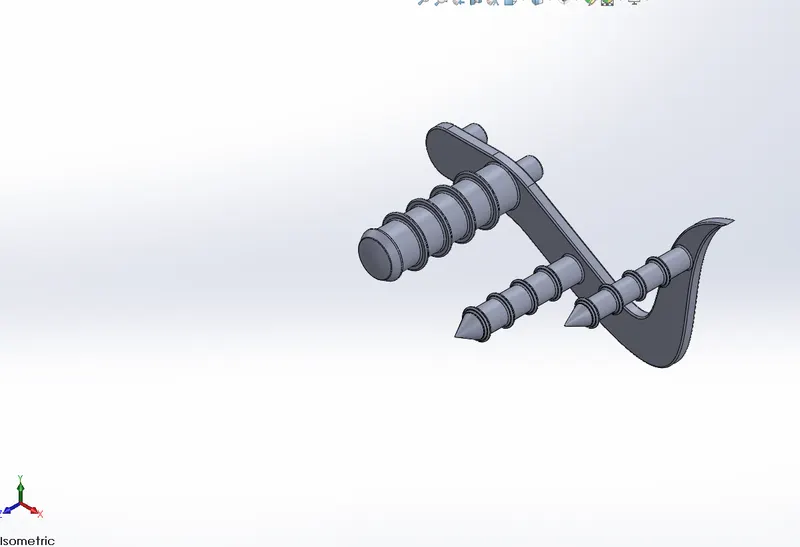
PEDAL
Sketch tools, Boss extrude, Fillet, Linear pattern Chamfer, Dome, Revolve.
OIL TANK
Sketch tools, Boss extrude, Combine, Shell, Fillet and Appearance.
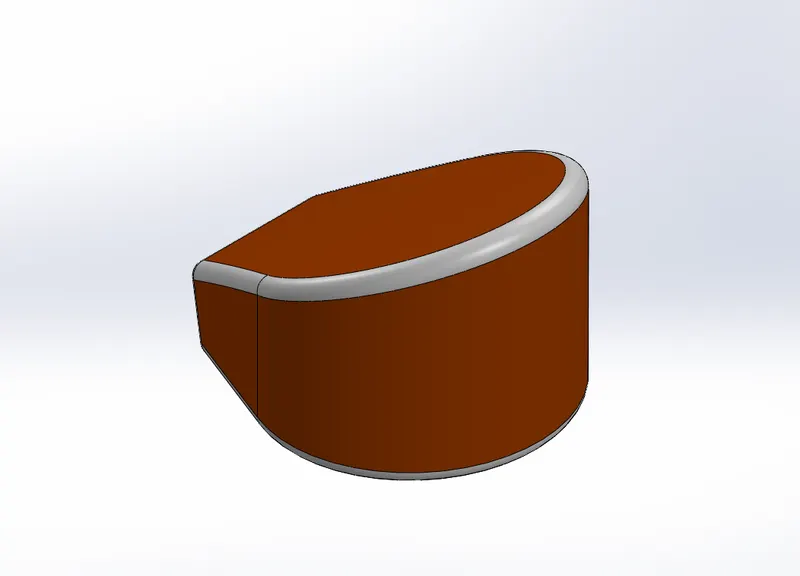
FRONT TIRE
Sketch tools, Revolve , Circular pattern, Revolved cut, Extruded cut, Combine, Chamfer, Fillet, Boss extrude and Apperance.
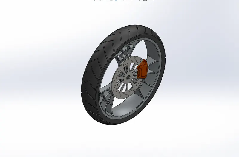
REAR TIRE
Sketch tools, Revolve, Circular pattern, Revolved cut, Extruded cut, Combine, Chamfer, Fillet, Boss extrude and Apperance.
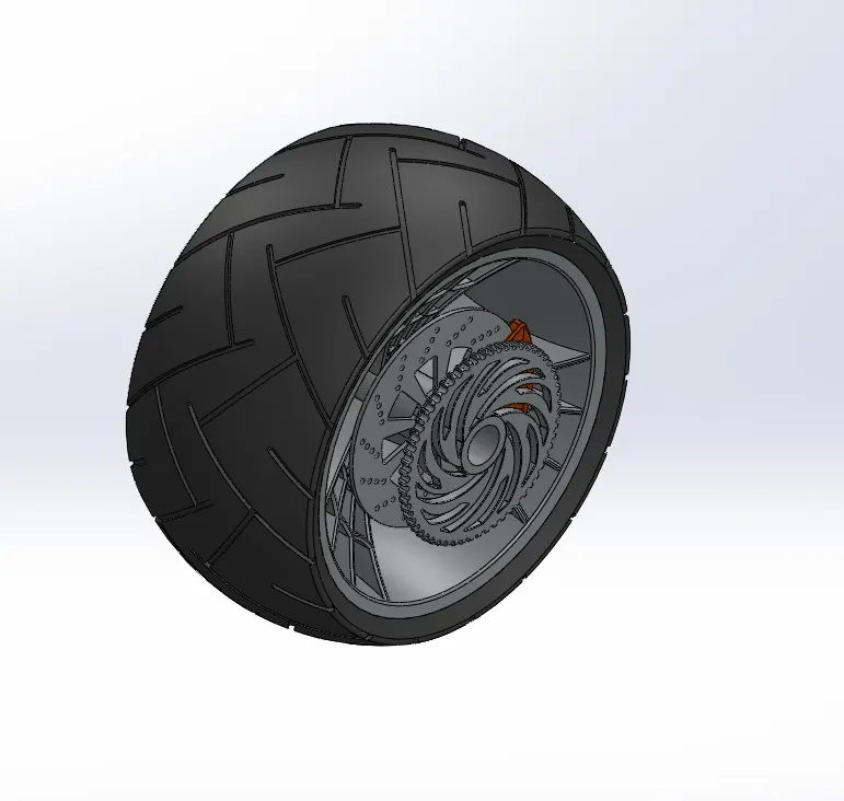
FORK
Sketch tools, Revolve, Boss extrude, Fillet, Linear pattern, Cut extrude, Dome, Cut revolve, Projected curve, Sweep, Refernce plane, Mirror and Combine.
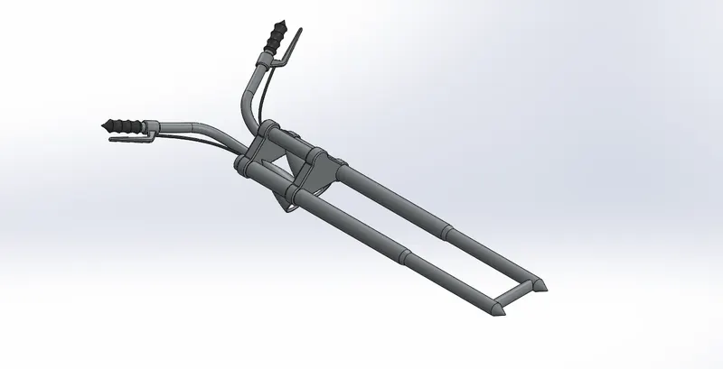
CHASSIS
Sketch tools, Sketch picture, Projected curve, Sweep, Mirror, Boss extrude, Cut extrude, Chamfer, Fillet, reference plane, Dome, Split, Combine, Revolve and Appearance.
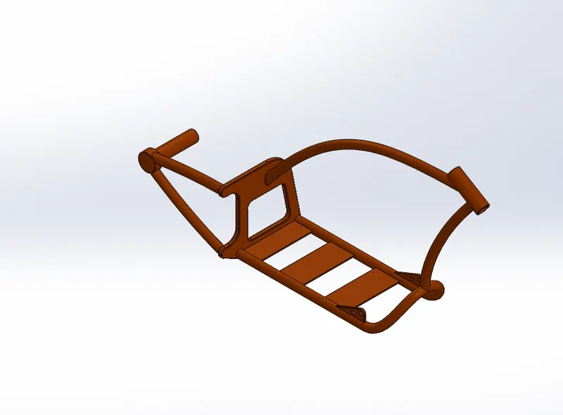
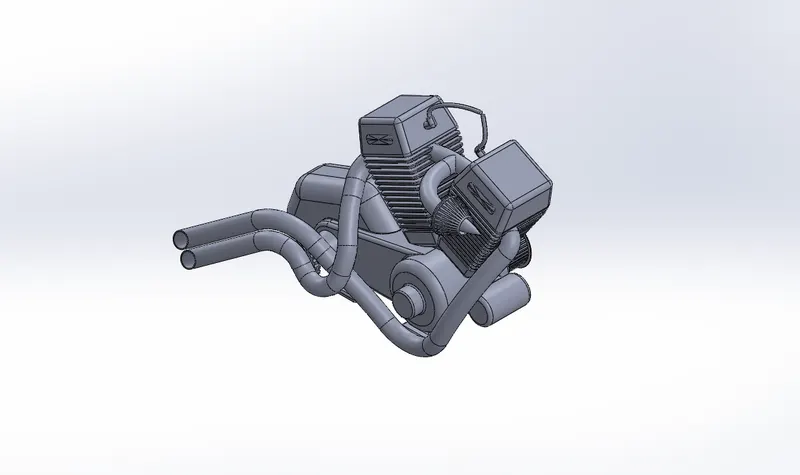
ENGINE
Sketch tools, Sketch picture, Boss extrude, Fillet, Revolve, Reference plane, Circular pattern, Dome, Cut extrude, Chamfer, Linear pattern, Mirror, Split, Combine, Sweep, Projected curve, Composite curve and Appearance.
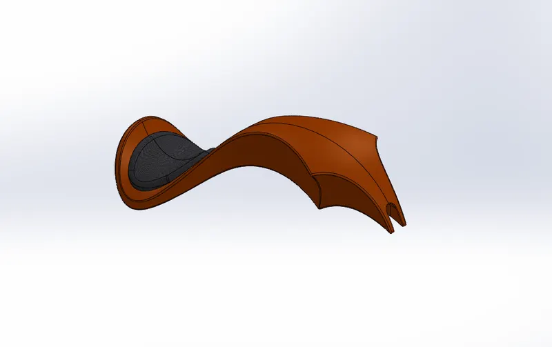
FUEL TANK
Sketch tools, Reference plane, Surface sweep, Surface trim, Projected curve, Surface loft, Boundary surface, Mirror, Surface knit, Surface extrude, Fillet, Cut sweep, Shell and Appearance.
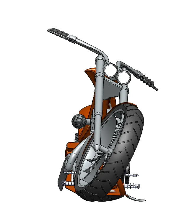
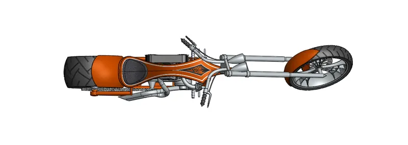
Picture of assembly:
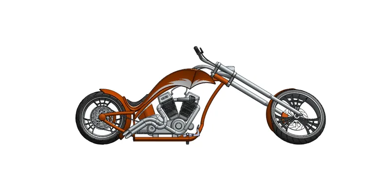
RENDERED IMAGES:
CONCLUSION:
The use of tools in this parts are learned. The tools used in this part can be used in multiple different ways to create the same. Finally the rendered images give a good idea of presenting a part at different suitable environments.