Multi-body Dynamics Simulation of a Piston Assembly
Aim: The goal of the study is to simulate the piston movement and study the linear displacement of the piston for variations in the piston-conrod assembly.
Background:
A piston is a component of reciprocating engines, reciprocating pumps, gas compressors, hydraulic cylinders, and pneumatic cylinders, among other similar mechanisms. It is the linear, reciprocating component of the cylinder that is transmits its linear movement to the crankshaft.
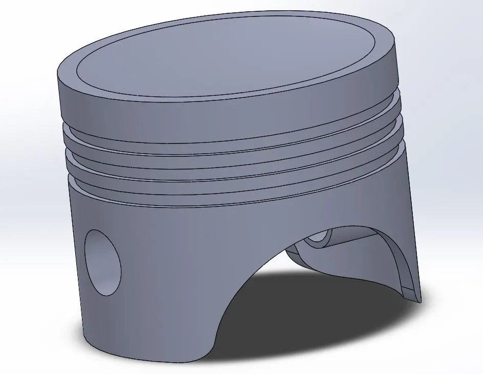
A piston alone forms only the head of the assembly. While it stores the air or the fresh charge and causes the compression, the motion is initiated via the crankshaft. The crankshaft is the rotational component of the system that is rotated by the piston as the combustion process pushes the piston down.
The crankshaft rotation is balanced with the help of counterweights as shown below. The CWs are on the opposite sides of the pivot point where the con-rod attaches.
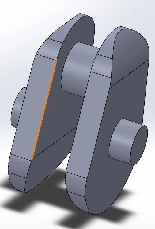
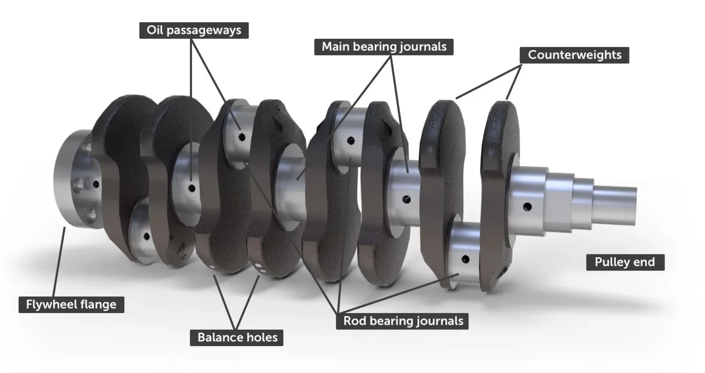
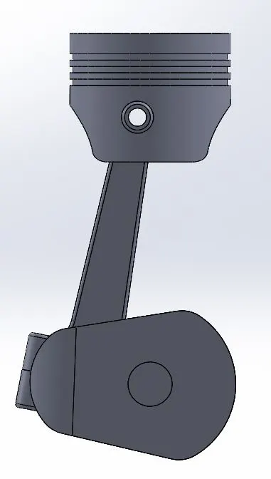
The connection between the Piston and the crankshaft is shown below:
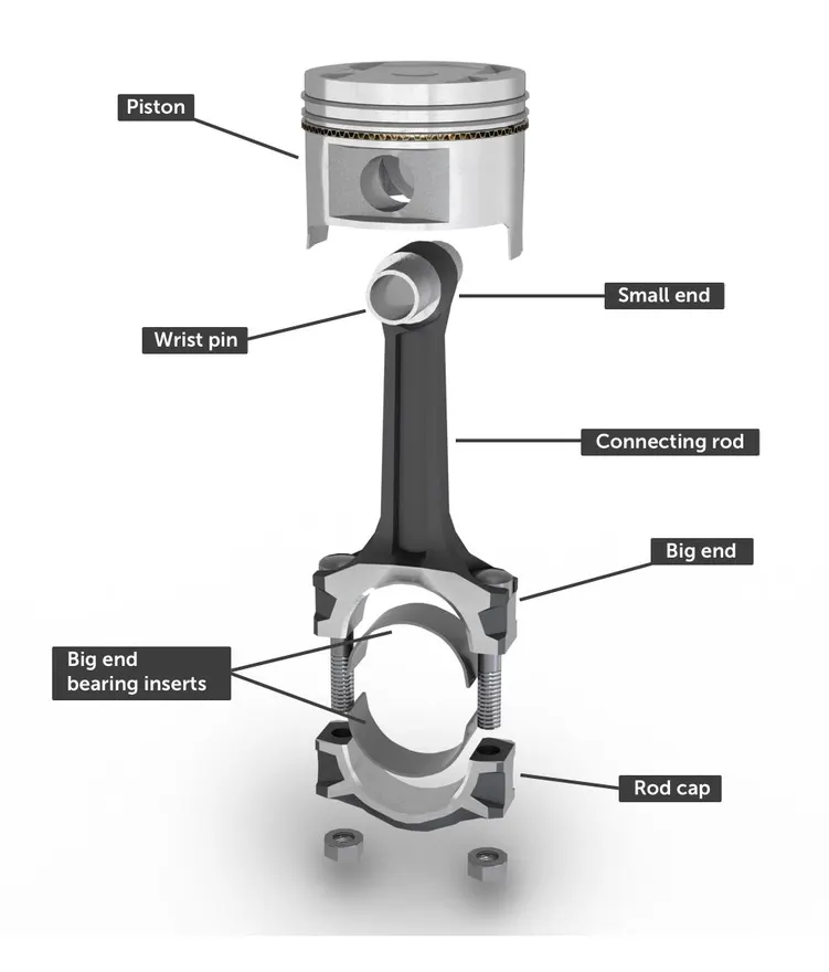
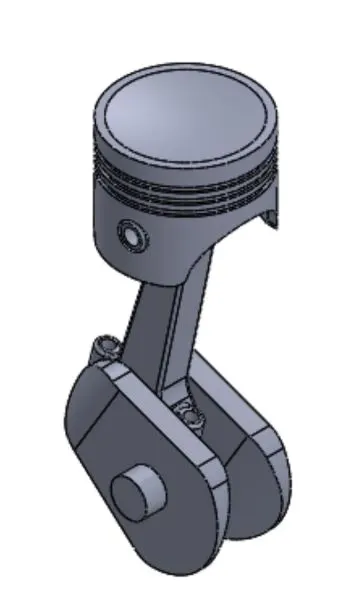
In this setup, we will be simulating 3 setups at 2000 RPM:
- Wrist pin in line with crankshaft axis- 0 offset
- Wrist pin to left- negative 10 mm offset
- Wrist pin to right- positive 10 mm offset
Procedure:
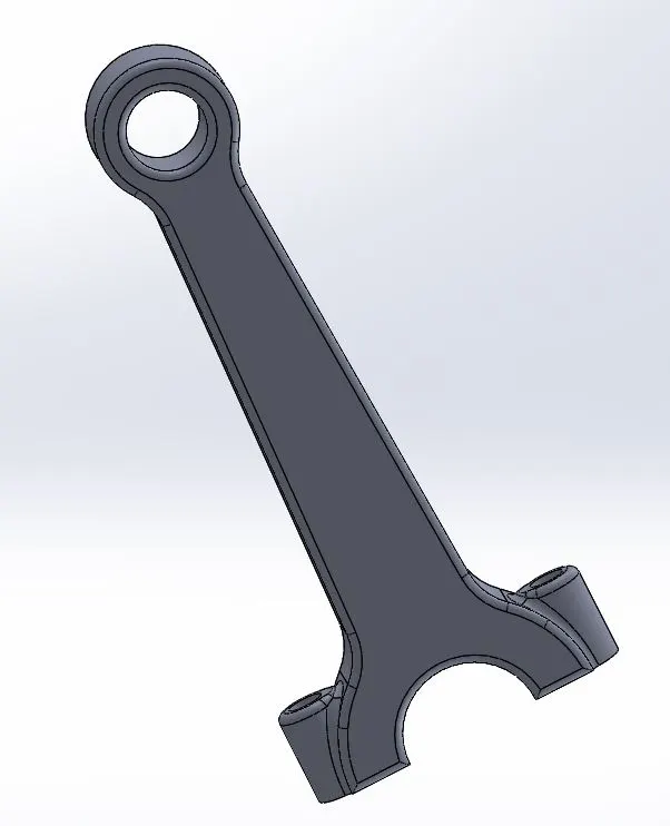
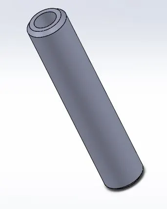
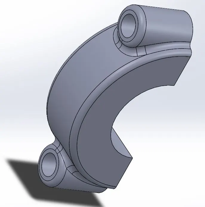
- With the dimensions given, model the piston, con-rod, wrist pin, end cap and crankshaft. Piston and Crankshaft are shown above. The other 3 are as follows:
- Carry out the assembly for the 3 cases mentioned above.
- In the motion analysis section, set the following parameters:
- FPS = 2000/60 = 33.333 RPS => 33.333 x 360 = 12000 FPS to get every degree as a frame.
- Precise contact
- Accuracy bar in the middle (this can help avoid simulation failures mid-simulation in lower-end systems)
- Gravity-> y-direction (downwards)
- Add 2000 RPM Clockwise rotation motor to the crankshaft axis
- Solid-body contacts:
- Crankshaft and end cap
- Crankshaft and Con-rod
- Con-rod and wrist pin
- wrist pin and piston
- Run the simulation for 5 seconds.
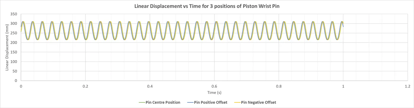
- Generate graphs of linear displacement vs time for the piston for all 3 cases and plot them in excel on one curve.
Results:
- Zero offset:
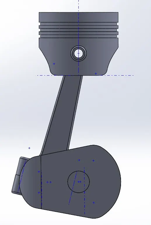
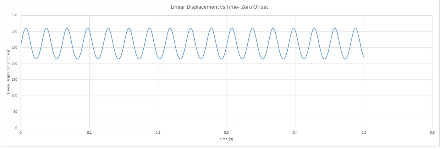
Animation- zero offset - Positive 10 Offset:
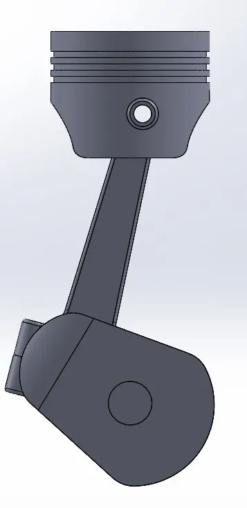
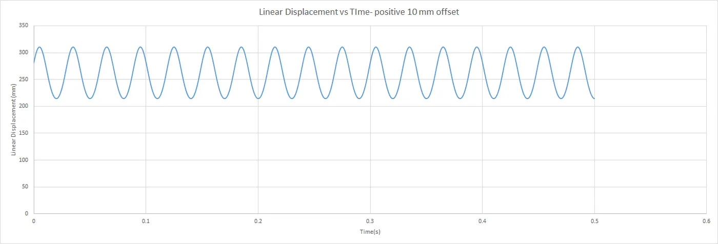
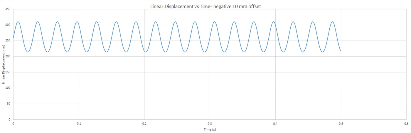
Animation- plus offset - Negative 10 offset:
- Combination graph:
Conclusion:
- Adding an offset shows that the TDC position of the offset cases is slightly lower than the zero offset case by 0.2mm. This is due to the offset making the conrod slightly inclined when the piston reaches the TDC or BDC. Since this number is very small, it can be ignored.
- Thee is an advantage to an offset setup. At zero offset, the crank and piston are completely vertical at the TDC and BDC, the power required to move the piston is the highest. The power requirement is reduced with an offset setup as the conrod is in an inclined state at TDC and BDC. Lesser resistance is developed and hence more power produced.
- We also notice a horizontal shift in the graph by a very small amount, which can also be considered negligible as the time period has stayed constant across all cases.