Motion Analysis of an IC Engine Valve Train
Aim: The goal of the project is to understand the construction of an IC Engine valve train, model the same, carry out a multi-body simulation in Solidworks.
Background:
An engine valve train is a mechanical system that operates the valves in an engine that allows for the fresh charge and exhaust gas flow in and out of the engine respectively.
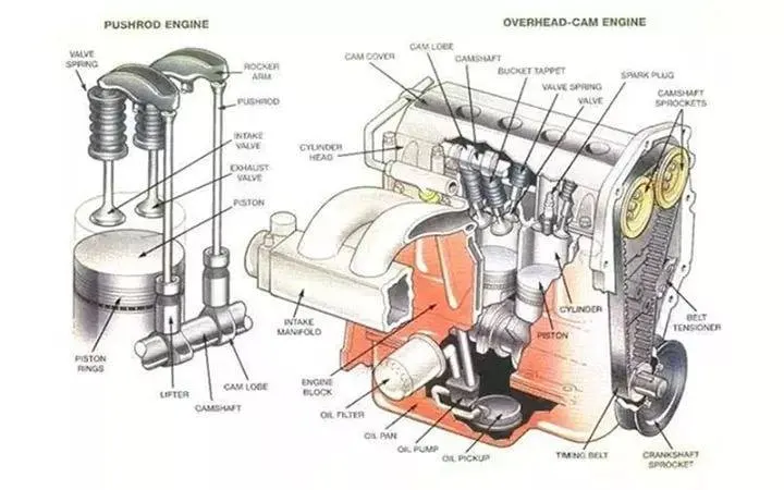
The above image shows a typical valve train assembly and its position in the engine. A valve train consists of the following parts:
- Valves
- Camshaft
- Pushrods
- Rocker Arms
- Valve spring
The camshaft is a shaft consisting of cams, which are lobe-shaped rotating solids that actuate the cams. The camshaft is driven via a chain drive coming directly (via reductions) from the crankshaft. The cam rotation moves the pushrods up and down, which in turn actuates the rocker arms. The movement of the rocker arms at precise timings pushes the valves down. Once the valve is opened, a fresh charge (intake valve) or exhaust gas (exhaust valve) flows through the valve openings. The cycle continues to keep the engine running.
In this simulation, we will be looking at a valve train's operation for 2 different values of Cam lift. Cam lift is derived with the formula as shown below (from the original problem question page):
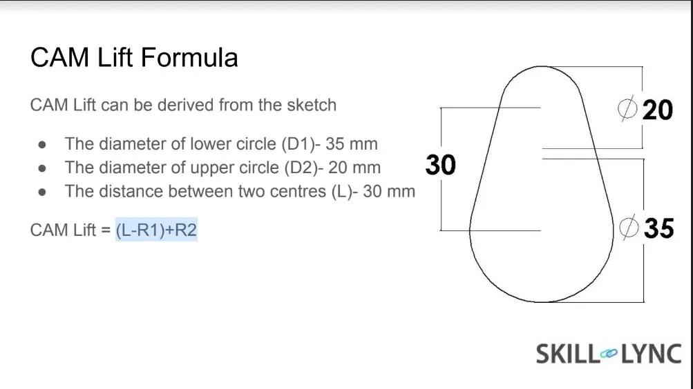
Here, the valve lift is the difference between the center distances and the difference between the center radiuses.
Below are the two cases:
| SL. No. | Cam Lift (mm) | RPM | Material | Centre Distance (mm) |
| 1 | 3.5 | 1500 | Cast Carbon Steel | 11 |
| 2 | 6 | 1500 | Cast Carbon Steel | 13.5 |
Procedure:
- Use the dimensions given to model the components
- Cam:
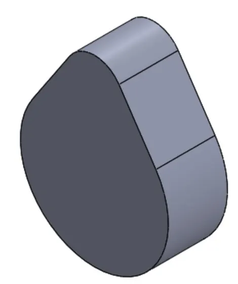
Model 2 cams, one for 11 mm center distance and 13.5 mm center distance. - Pushrod:

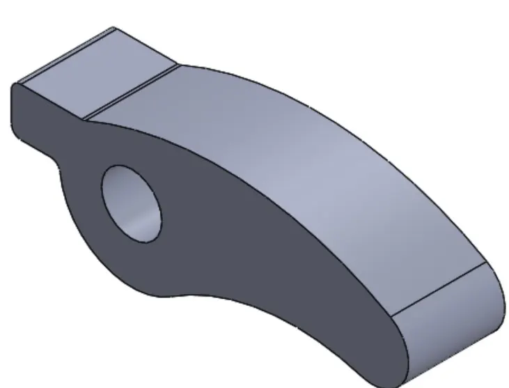
- Rocker Arm:
- Valve
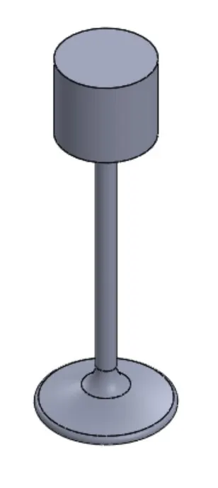
- Valve Stem
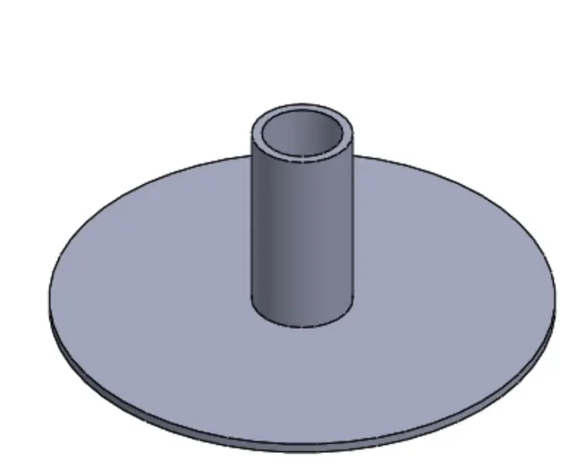
- Cam:
- Assemble the components into the valve train:
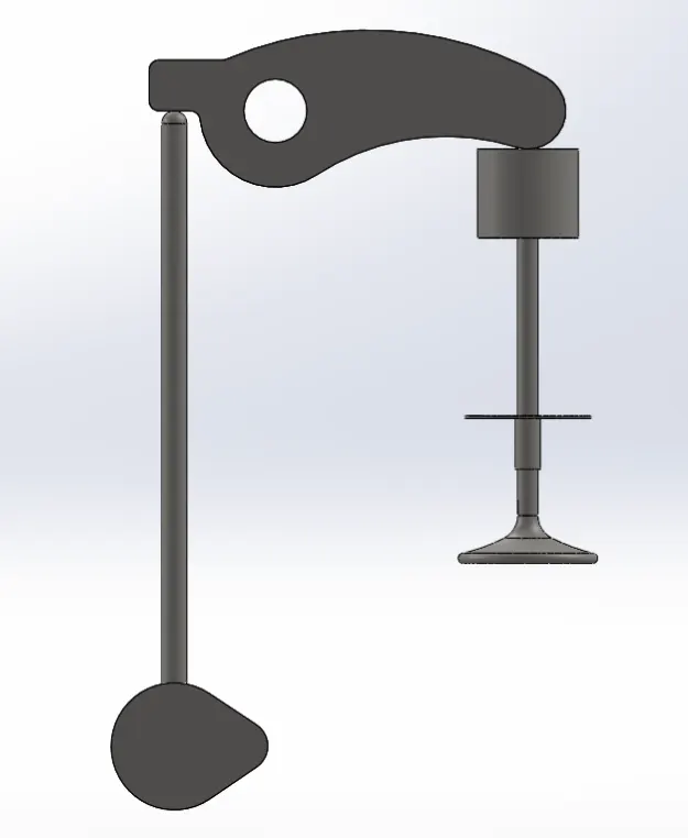
- Ensure the following points when assembling the components:
- The distance of Cam center from rocker arm center plane = 125 mm
- Distances of Cam center and pushrod central axis from central vertical plane = 20 mm to the left
- The distance of Valve stem from the central vertical plane = 50 mm to the right
- Start the Motion Analysis:
- 1500 RPM = 25 RPS
FPS = 25 x 360 degrees = 9000 - Use precise contact
- Motor RPM at Cam centre = 1500
- 1500 RPM = 25 RPS
- Add spring along the shaft of the valve between the stem and the bottom of the valve head
- Spting constant = 10 N/mm
- Pre-tensioned spring length = 60 mm
- Run the simulation for 0.2 seconds
- Obtain plots for the following:
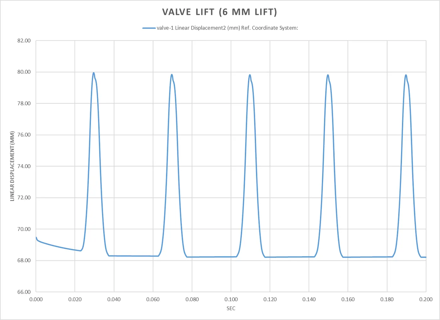
- Valve Lift
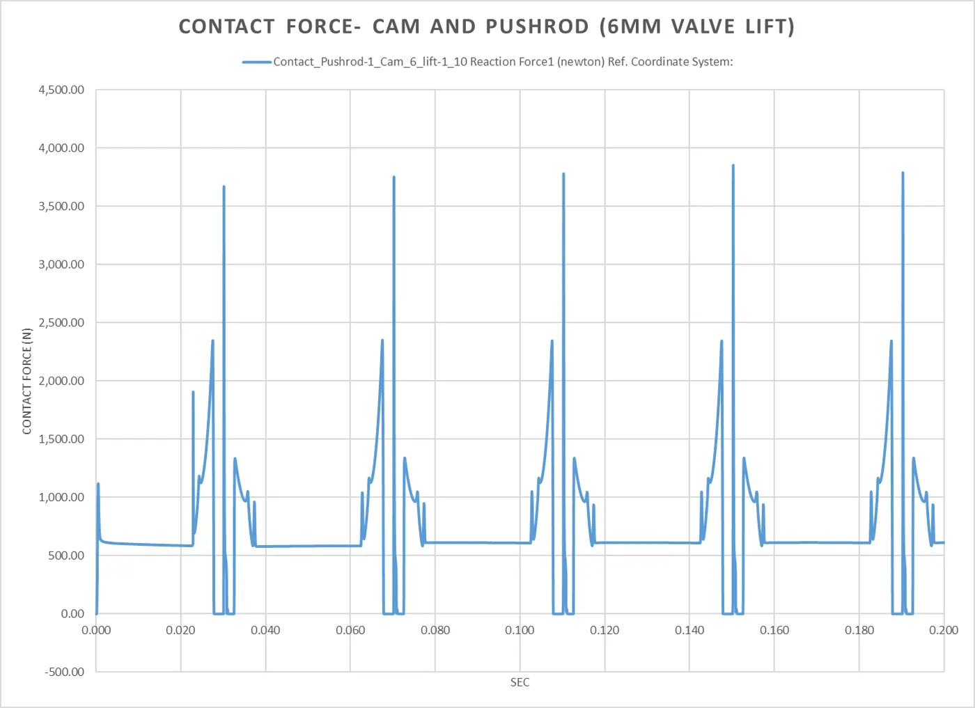
- Contact force- Cam and Pushrod
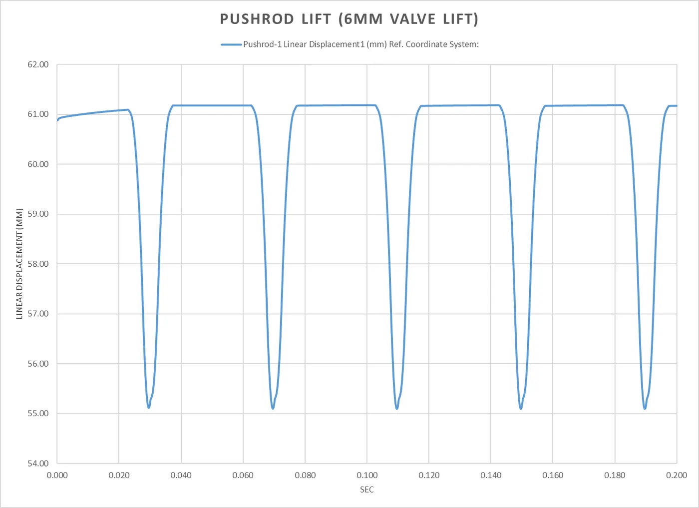
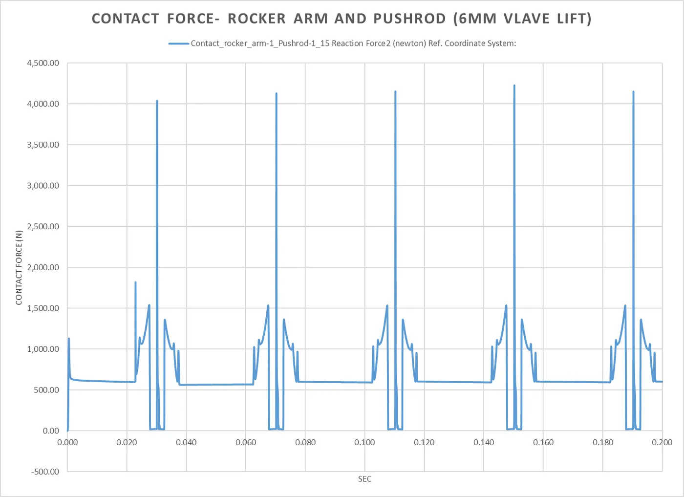
- Contact force- Pushrod and Rocker arm
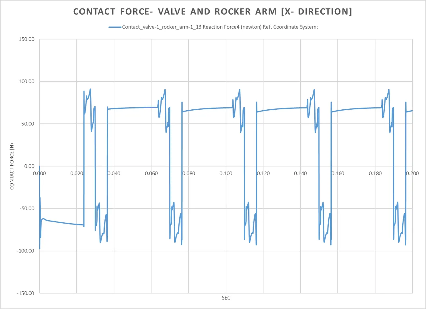
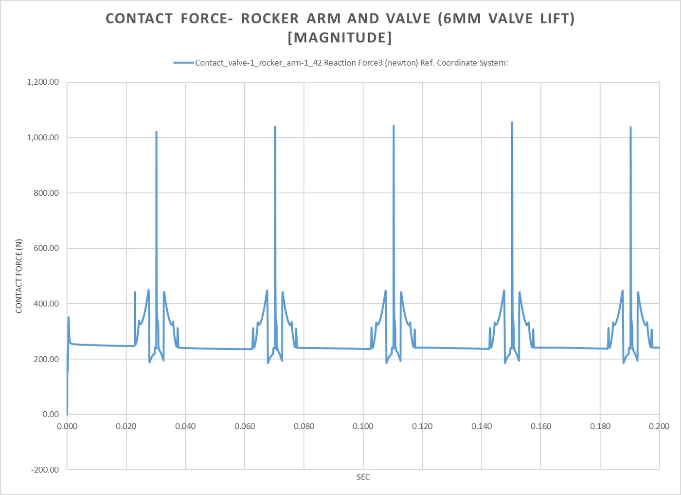
- Contact force- Rocker arm and Valve [Magnitude and X Direction]
Results:
- Cam lift- 3.5 mm:
- Valve Lift:
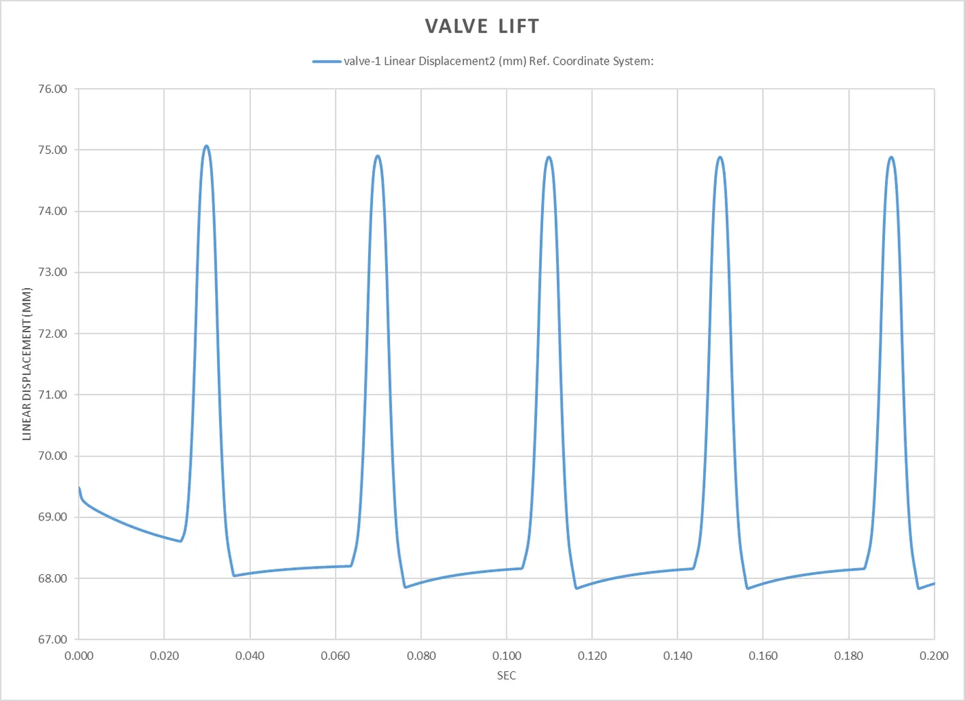
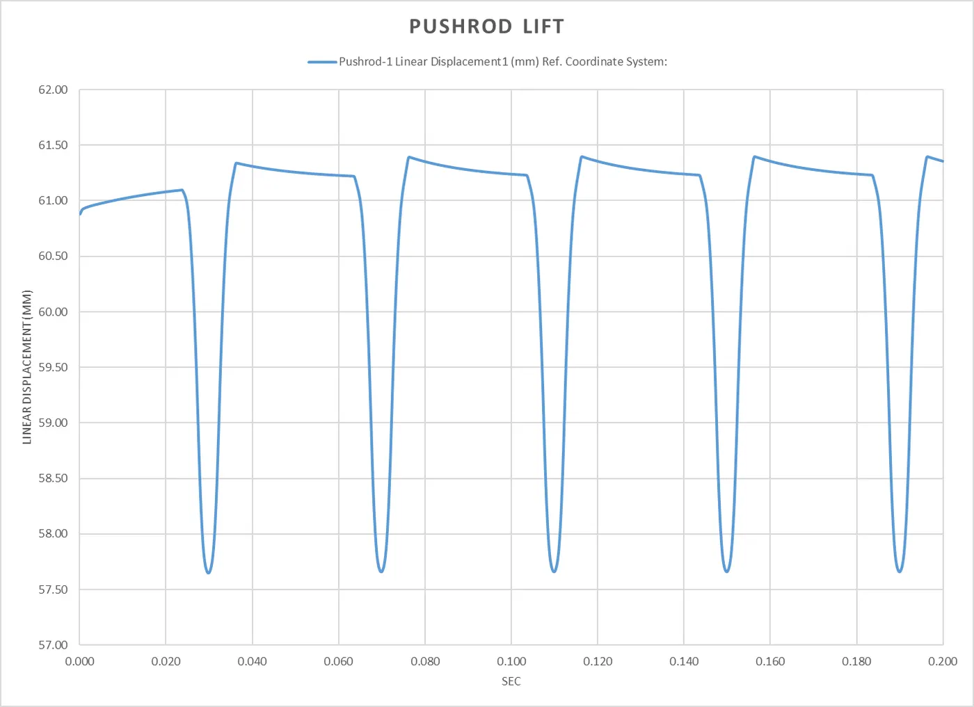
- Contact Force- Cam and Pushrod:
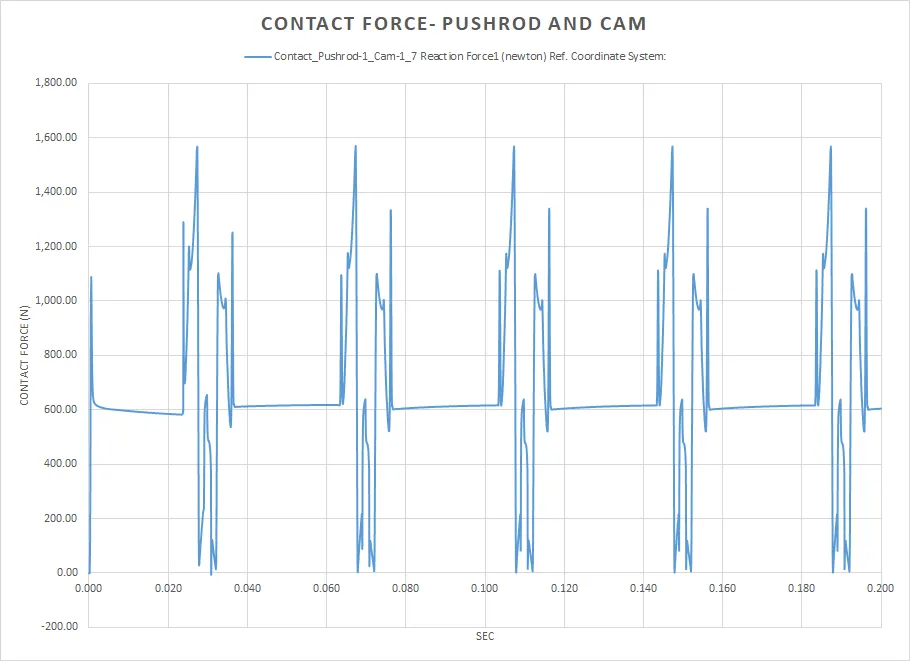
- Contact Force- Pushrod and Rocker Arm:
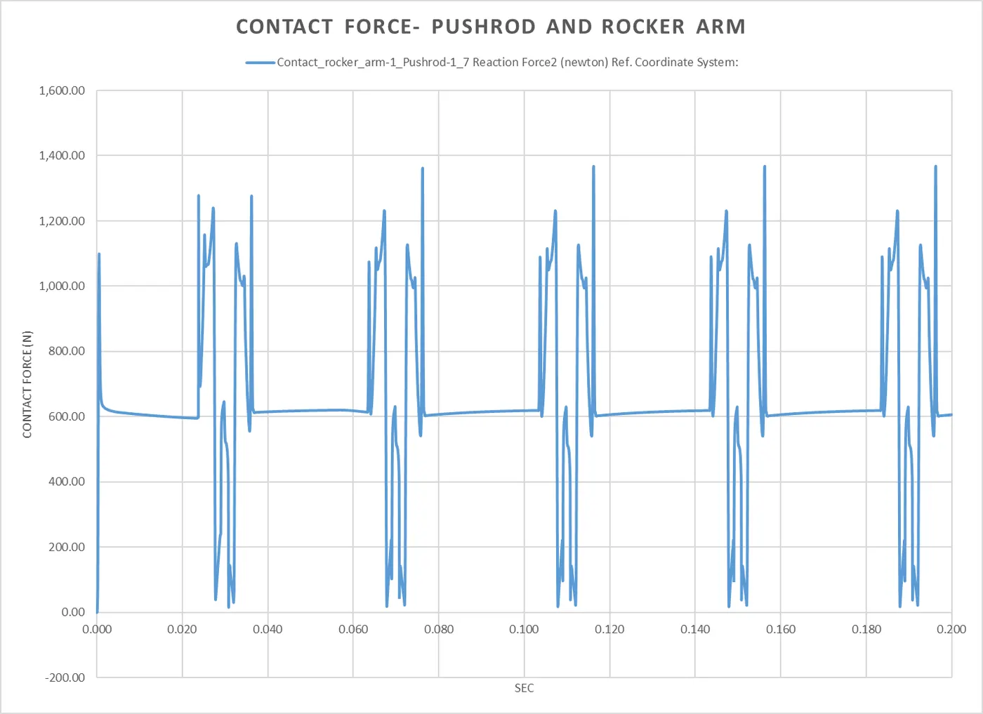
- Contact Force- Valve and Rocker Arm:
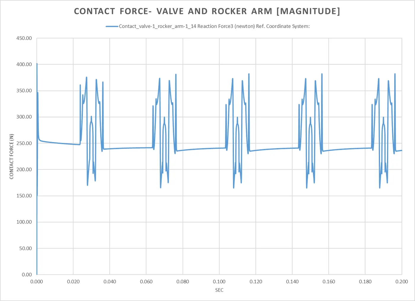
- Valve Lift:
- Cam lift- 6 mm:
- Valve Lift:
- Contact Force- Cam, and Pushrod:
- Contact Force- Rocker Arm and Pushrod:
- Contact Force- Rocker Arm and Valve:

- Valve Lift:
Conclusion:
- The X-direction graph shows a different trend than the magnitude graph because it is indicating friction. The only force that acts in the X direction is the sliding force between the face of the rocker arm and the top of the valve. As we know that the rocker arm moves in 2 different directions, one towards the origin and one away as it oscillates, it first registers positive and then negative force.
- The magnitude is higher for the 6mm valve lift, although with the greater lift we also have more fresh charge going into the engine, thereby allowing for more power.
Animations: