Hood design-Week 2
Aim: To design the hood assembly for a car using the given Class-A surface of the hood and the hinge and the striker assembly. Also, design the inner panel of the hood using the given master section.
Hood/Bonnet: Hood or Bonnet as it is known around the globe is the covering made of sheet metal and placed over the engine compartment of a car to shield the engine from the external factors and also give an aesthetic look to the car. The design of hood is done considering the pedestrian safety norms for an adult and a child separately.
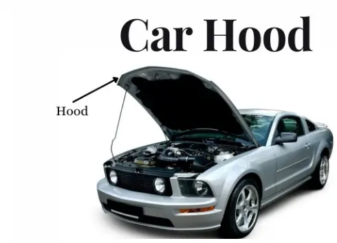
Fig. 1: Car Hood
Hood Assembly consists of the following parts which are manufactured separately and then assembled together.
- Hood Outer Panel
- Hood Inner Panel
- Hinges
- Striker
- Reinforcements
- Hood Support
The components of the assembly are manufactured using sheet metal operations, namely Deep Drawing, Piercing, Hemming and Embossing.
In this project, the design of the Hood Assembly is made by following the Top-Down Approach for designing.
The master section to be followed is as shown below:
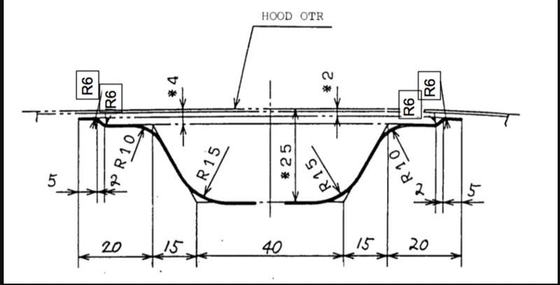
Fig. 2: Master Section of Hood Inner Panel
Following are the parts of the hood assembly and their design procedure is described as follows:
- Hood Outer Panel: The outer panel of the hood assembly is designed by keeping the aesthetic appearance of the car as first preference. It forms a particular pattern that matches with the other components around the hood. To keep the appearance clean, welding process is not used on the outer panel as it will create weld spots and ruin the appearance. Hence, the hemming process is employed and the assembly is done.
The Class-A surface of the hood outer panel is shown below:
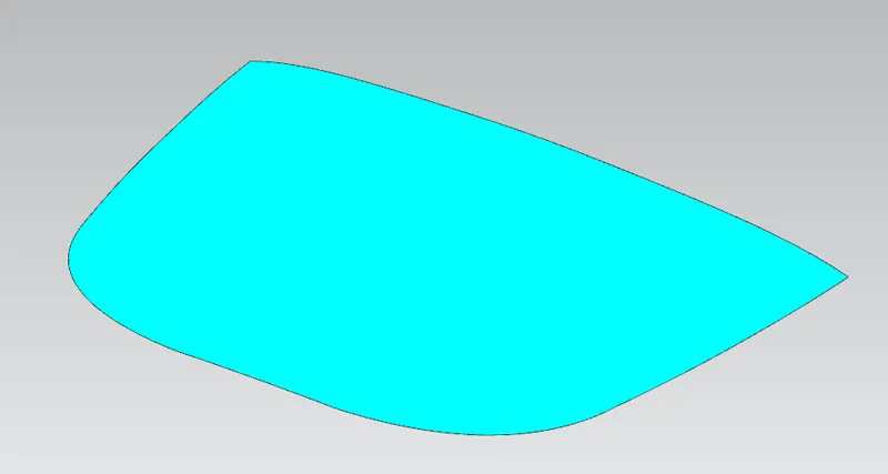
Fig. 3: Class-A surface of outer panel
The outer panel of the hood assembly is shown below:
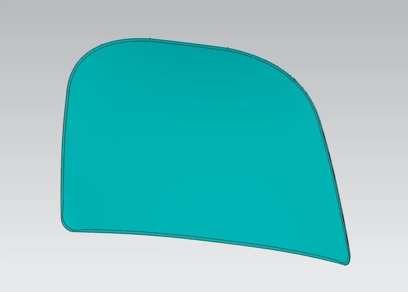
Fig. 4: Isometric View of the Outer Panel.
- Hood Inner Panel: The master section shown above needs to be developed to create the hood inner panel. The main purpose of the inner panel is to give adequate stiffness to the hood assembly and also provide base support to mount various other components such as hinge assembly, striker and one end of the hood support rod.
In this case, the inner panel is developed according to the master section by using ‘Offset Surface’ command in NX CAD to offset the given Class-A surface and then trim them appropriately. Also, the embossed features were made using the ‘Law Extension’ and ‘Trim and Extend’ commands. The cut-out are made to reduce the weight of the panel and also provide the mastic points which will be used to join the outer panel and the inner panel.
Next, the supporting components were placed and then the embossed features to mount those components were made on the inner panel. The inner panel is shown below:
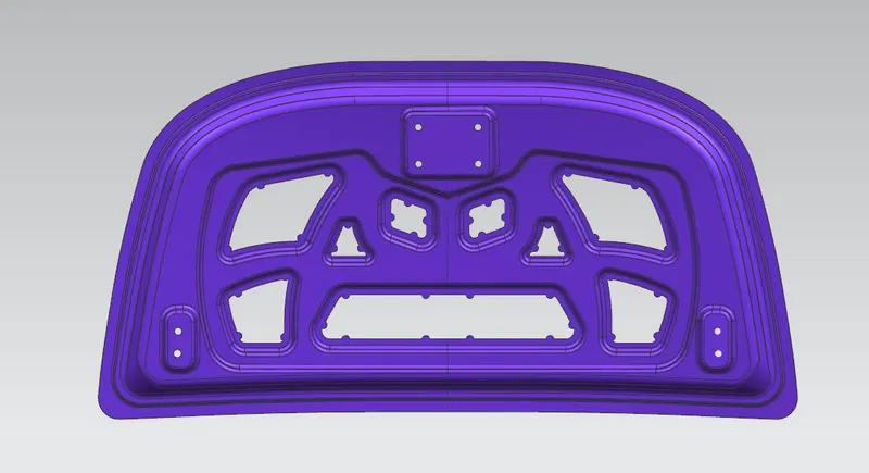
Fig. 5: Front view of inner panel
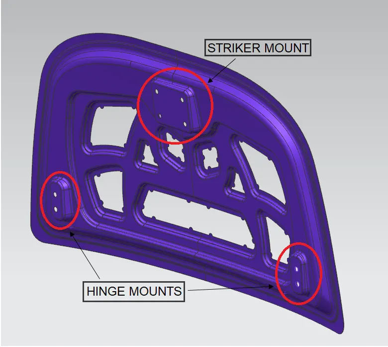
Fig. 6: Isometric view of the Inner Panel showing the hinge mounts and the striker mount
- Hinge Assembly: It is used to join the hood to the engine compartment and facilitate the movement of the hood. The rotary movement of the hinge about the axis helps to the open and close the hood easily. The hinge assembly is shown below:
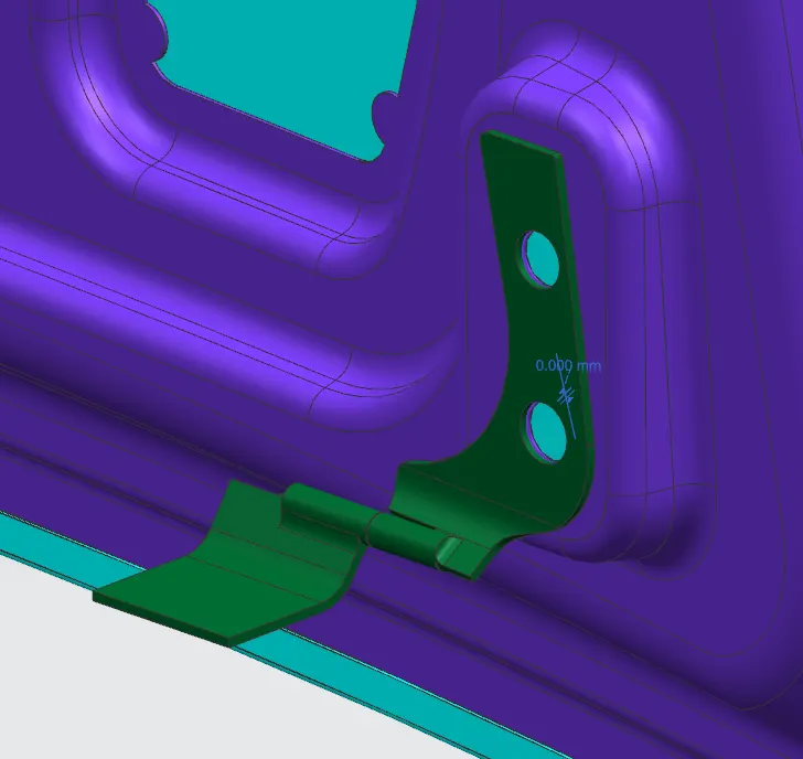
Fig. 7: Hinge assembly is placed on the emboss
- Striker / Latch: The striker is a part of the locking mechanism used to lock the hood on the engine compartment which is joined to the inner hood panel. When the hood is closed, the striker locks with its counterpart on the engine compartment and does not open when the car is moving. The striker is shown below:
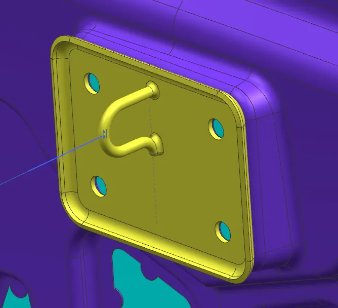
Fig. 8: Striker is placed on emboss.
Placing the Hinge and the Striker:
- On the inner panel, the hinge needs to be mounted in the corner. The hinge assembly is placed approximately in the required place and then emboss is drawn around it.
- The flat faces of the hinge and emboss are then constrained to place the hinge assembly on the right side.
- Next, use ‘Mirror Assembly’ command to place the hinge assembly on the left side.
- Put points at the center of the hinge cylinders on both the assemblies. Join them using the line which is parallel to the X axis of the hood. This is the axis about which the hood will rotate.
- Draw a circle with on the center plane of the inner panel with the axis as center point. Draw a horizontal reference line and a construction line at some angle.
- Draw another random line and make it tangent to the circle at the point where the second construction line meets the circle. When the angle of the second line is changed the tangent line also moves.
- Similarly, on the striker part, draw a line perpendicular to the striker face and passing through the center of the lock.
- Constrain the circle on the inner panel and the line on the striker. When the dimensions on the circle are changed, the striker moves around.
- Place the striker at suitable position and then draw emboss on the inner panel.
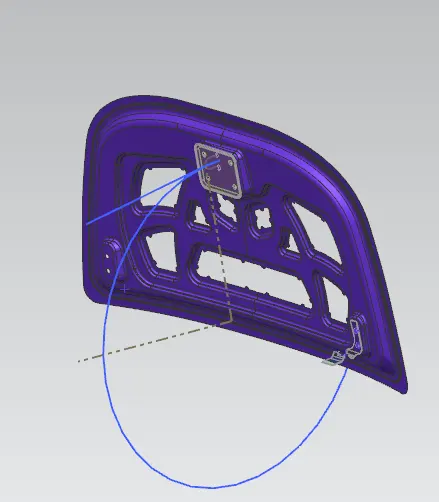
Fig. 9: The circle of the striker movement.
Mastic Sealant: The inner panel and the outer panel are joined using the mastics. Initially it is a paste which is placed at mastic points between the panels and then is heated. It turns into rubber that enhanced the NVH characteristics and seal the panels together.
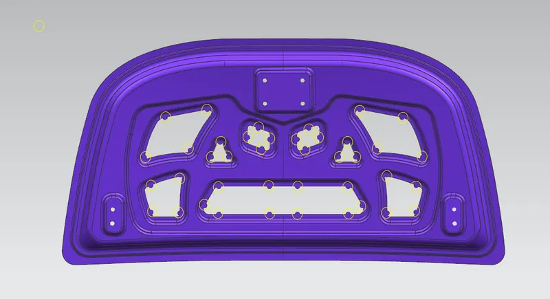
Fig. 10: Mastics Points
Sheet Metal Operations:
- Hemming: Hemming is the process of fitting together parts by rolling over one part over the edges of the other part. Hood, Doors and Boot Lids of an automobile are assembled using the hemming process.
In this case, the outer panel is subjected to hemming process and the edges are rolled over the inner panel and fixed together. There is a small gap between the sheets to fill the hemming sealant which solidifies and holds the panels together. Also, a corner relief is provided to give proper hemming at the corners.
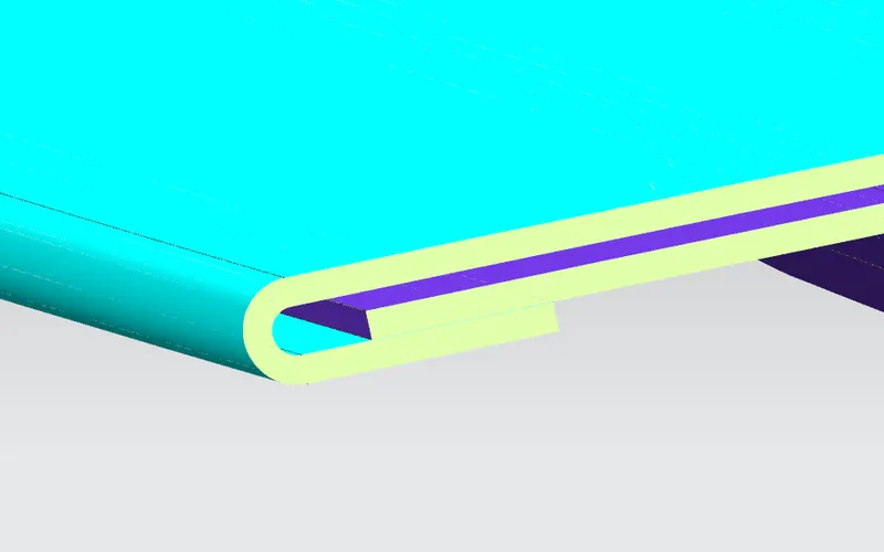
Fig. 11: Hemming process on the outer panel.
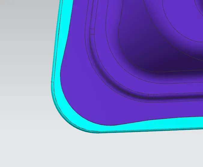
Fig. 12: Corner relief provided on the outer panel
- Deep Drawing: It is a sheet metal forming process similar to the punching process. The sheet metal to be formed is clamped and the die is kept below the sheet metal. The punch is then forced from above to give the sheet metal the required shape.
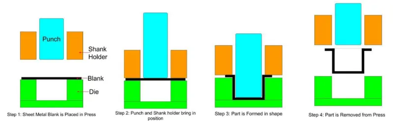
Fig. 13: Deep drawing process
- Embossing: It is a sheet metal forming process to create projection on the sheet metal on the either side of the sheet. Inner panel of the hood has such emboss provided to give it the required strength and transfer the crash forces towards outside of the car.
- Piercing: It is a material removal process from a sheet metal to reduce weight and remove the unwanted material by using blanking punch and dies.
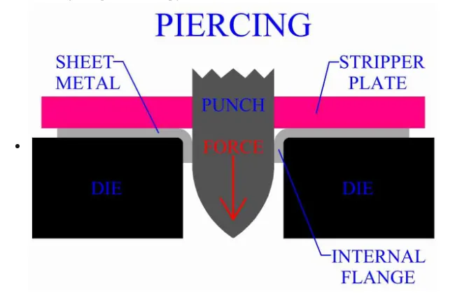
Fig. 14: Piercing process schematic
The hood assembly is as shown below:
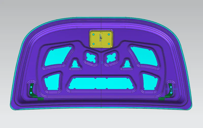
Fig. 15: Front view of the Hood Assembly
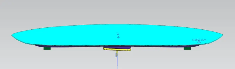
Fig. 16: Top view of the Hood Assembly
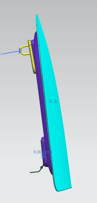
Fig. 17: Right view of the Hood Assembly
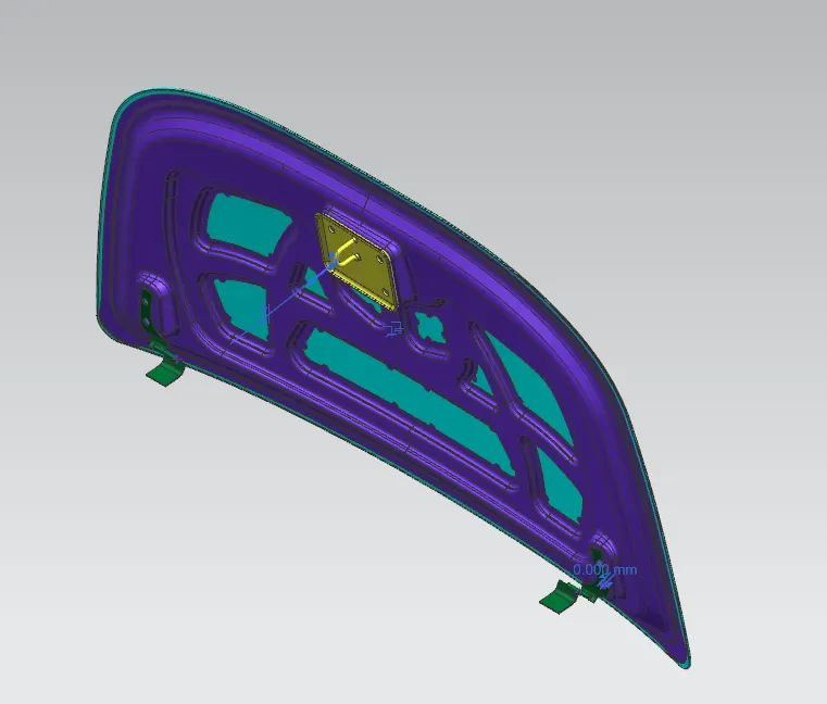
Fig. 18: Isometric view of the Hood Assembly
Conclusion: The hood assembly is created successfully using the given master section and constrained the components at appropriate positions.