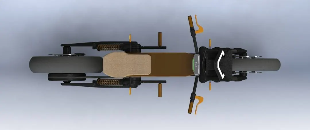
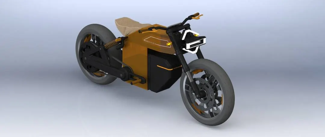
MODELLING AND ASSEMBLY OF HARLEY-DAVDISON REVIVAL
MODELLING AND ASSEMBLY OF HARLEY-DAVDISON REVIVAL:
- ABSTRACT:
- Computer-aided design (CAD) is the use of computers to aid in the creation, modification, analysis, or optimization of a design.
- CAD software is used to increase the productivity of the designer, improve the quality of design, improve communications through documentation, and to create a database for manufacturing.
- CAD may be used to design curves and figures in two-dimensional (2D) space; or curves, surfaces, and solids in three-dimensional (3D) space.
- CAD is an important industrial art extensively used in many applications, including automotive, shipbuilding and aerospace industries, industrial and architectural design, prosthetics and many more.
- In this project we have to Design and Modelling of an Electric Motorcycle using SOLIDWORKS.
-
INTRODUCTION:
- Electric Motorcycle is a modification of conventional bike which uses electric motor to replace the Engine.
- It reduces the uses of motor bikes which reduces the pollution as it is eco-friendly vehicle.
- In this project is to Design and Modelling of “HARLEY-DAVDISON REVIVAL ”using Solidworks, by using Part Modelling. Surface Modelling and converting them to 3D models.
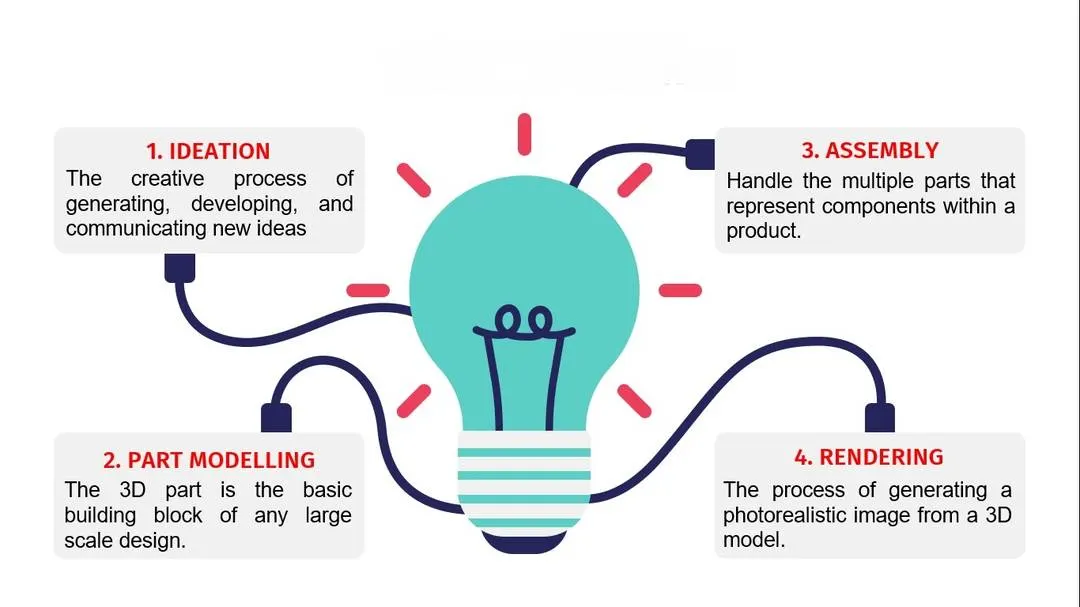
- Assembling the parts to create the final model and giving it a realistic view by rendering the model.
- The model is created in SOLIDWORKS 2017.
- The Assembled model is rendered using PHOTOVIEW 360 & SOLIDWORKS VISUALIZE.
-
DESIGN METHODOLOGY:
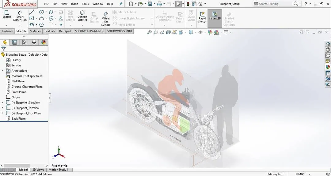
- BLUEPRINT SETUP:
- DESCRIPTION:
- Software Used:
- SOLIDWORKS 2017
- SOLIDWORKS VISUALIZE 2017
- Parts of an Harley-Davidson Revival:
- Chassis
- Front Fork
- Swing Arm
- Front Wheel
- Rear Wheel
- Engine (Controller, Battery, Electric Motor)
- Adaptable Foot Peg
- Seat
- Suspension
- Transmission Belt
- Commands Used:
- SKETCHING:
- Sketch
- Line
- Rectangle
- Circle
- Arc
- Spline
- Fillet
- Mirror
- Dynamic Mirror
- Sketch Picture
- Smart Dimension
- Offset Entities
- Convert Entities
- Intersection Curve
- Trim Entities
- Extend
- Linear Sketch Pattern
- Circular Sketch Pattern
- FEATURES:
- Extruded Boss: Extruded a sketch or selected sketch contours in one or two directions to create a solid feature.
- Revolved Boss: Revolves a sketch or selected sketch contours around an axis to create a solid feature.
- Swept Boss: Sweep a closed profile along an open or closed path to create a solid feature.
- Lofted Boss: Adds material between two or more profiles to create a solid feature.
- Extruded Cut: Cuts a solid model by extruding a sketched profile in one or two directions.
- Revolved Cut: Cut a solid model by revolving a sketched profile around an axis.
- Swept Cut: Cuts a solid model by sweeping a closed profile along an open or closed path.
- Fillet: Creates a rounded internal or external face along one or more edges in solid or surface feature.
- Chamfer: The chamfer tool creates a beveled feature on selected edges, faces, or a vertex.
- Shell: Removes material from a solid body to create a thin walled feature.
- Reference Geometry: It defines the shape or form of a surface or a solid.It includes items such as planes, axes, coordinate systems, and points. You can use reference geomentry in the creation of several kinds of features.
- Curves: You can create several types of 3D curves.
- Dome: Select one or more planar or non-planar faces you can apply domes to faces whose centroid lies outside the face this allows you to apply domes to irregularly shaped countours.
- Combine: It can manually combine the solid bodies.
- Split: It is able to split faces on multiple bodies.
- Pattern: Pattern repeats the selected features in an array based on a seed feature. You can create a linear pattern, a circular pattern, a curve driven pattern, a fill pattern, or use sketch points or table coordinates to create the pattern.
- Mirror: Mirror copies the selected features or all features, mirroring them about the selected plane or face.
- SURFACING:
- Surfaces are a type of geometry that can be used to create solid features. Surface tools are available on the Surfaces toolbar.
- SKETCHING:
-
-
PART MODELLING:
-
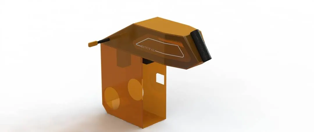
Chassis: All the components of a motorcycle, like the suspension, wheels, fuel tank, seats, handlebars etc., are attached to this base structure which lends a motorcycle its strength and ability to handle well.
- Features Used:
- Extruded Boss
- Extruded Cut
- Revolve
- Split
- Chamfer
- Fillet
- Mirror
- Rendering:
- Features Used:
-
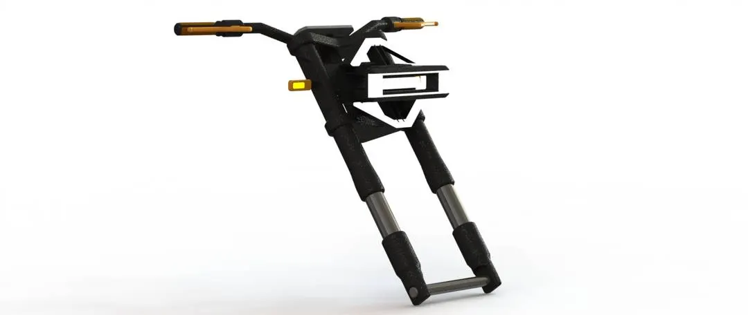
Front Fork: It connects a front wheel and axle to its Chassis, typically via a yoke, also known as a triple clamp, which consists of an upper yoke joined to a lower yoke via a steering stem, a shaft that runs through the steering head, creating the steering axis.
- Features Used:
- Revolved Boss
- Loft
- Extruded Boss
- Linear Pattern
- Extruded Cut
- Swept Boss
- Revolved Cut
- Ectruded Cut
- Combine
- Chamfer
- Fillet
- Circular Pattern
- Mirror
- Rendering:
- Features Used:
-
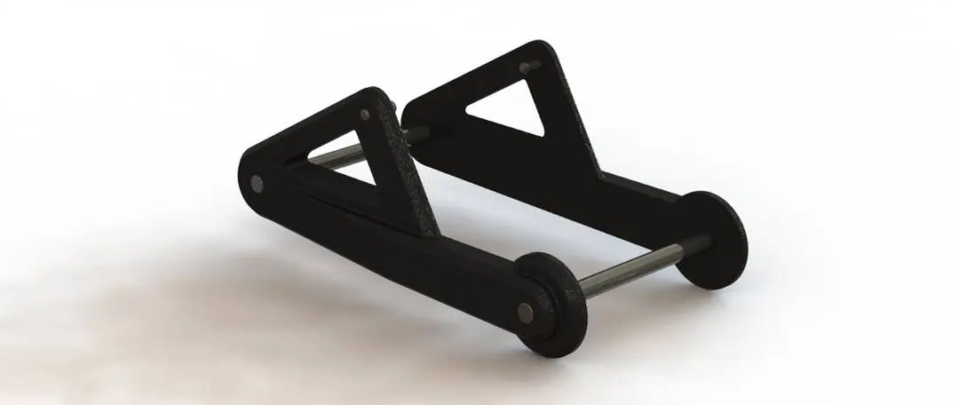
Swingarm: It is known as a swing fork or pivoted fork, is a single or double sided mechanical device which attaches the rear wheel of a motorcycle to its body, allowing it to pivot vertically.
- Features Used:
- Extruded Boss
- Extruded Cut
- Chamfer
- Fillet
- Mirror
- Rendering:
- Features Used:
-
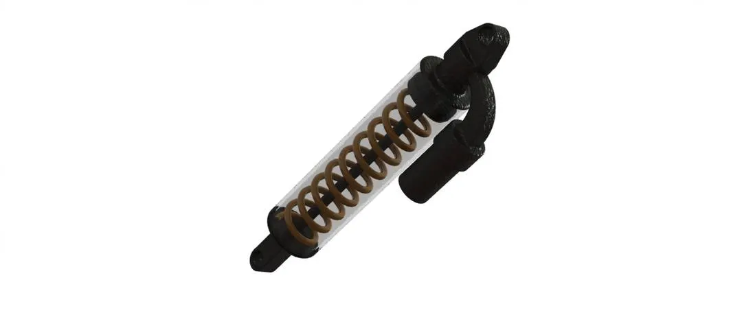
Suspension: The system of springs and shock absorbers by which a vehicle is supported on its wheels.
- Features Used:
- Extruded Boss
- Revolved Boss
- Extruded Cut
- Sweep
- Fillet
- Rendering:
- Features Used:
-
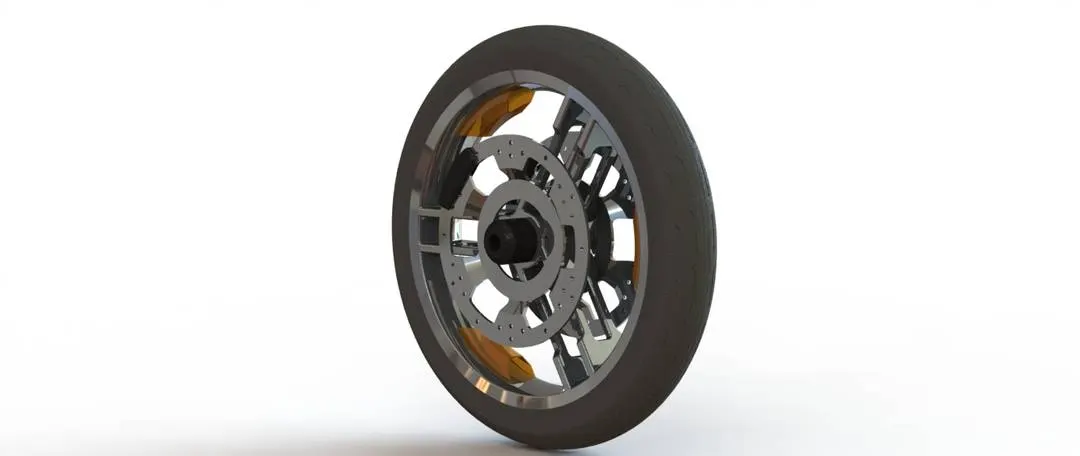
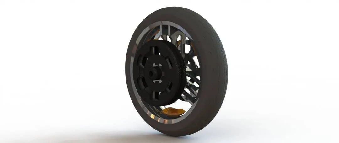
Wheel: The model is the combination of different solid bodies like Rim, Sprocket, Rotor, Caliper and Tyre.
- Features Used:
- Revolved Boss
- Extruded Boss
- Revolved Cut
- EXtruded Cut
- Circular Pattern
- Shell
- Chamfer
- Fillet
- Mirror
- Combine
- Rendering:
- Front Wheel:
- Rear Wheel:
- Features Used:
-
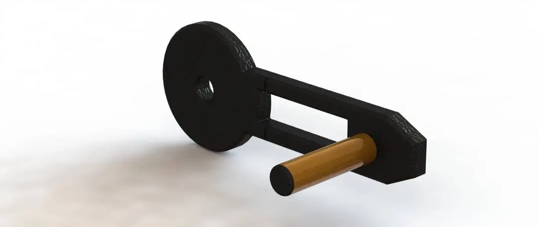
Adaptable Footpeg: The footpeg unit rotates and extends to be adaptable to the riders preferences. It also doubles as the kickstand when rotated at 90 degrees.
- Features Used:
- Extruded Boss
- Extruded Cut
- Chamfer
- Fillet
- Rendering:
- Features Used:
-
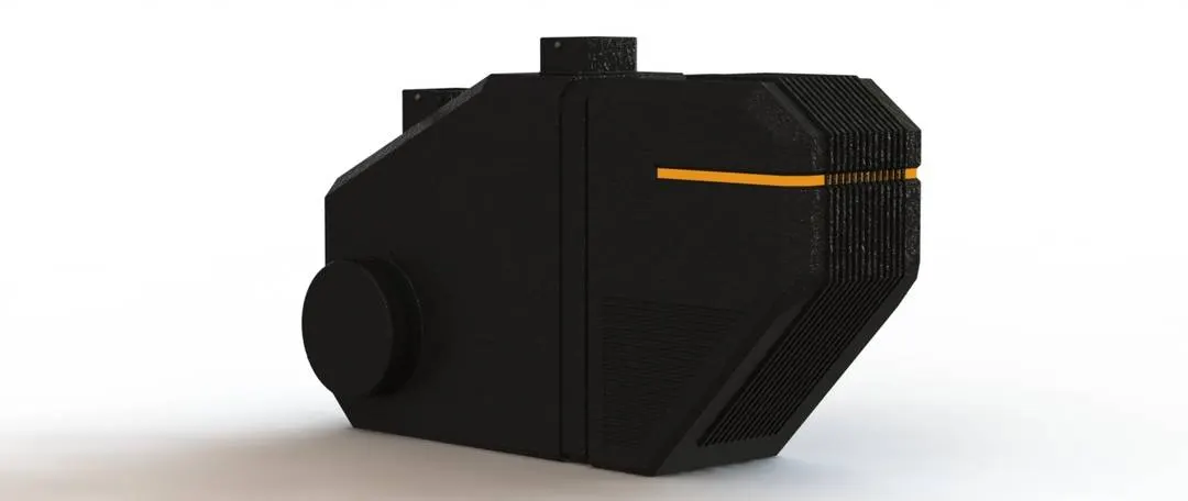
ENGINE: (Controller, Battery, Electric Motor)
- Features Used:
- Extruded Boss
- Extruded Cut
- Linear Pattern
- Swept Cut
- Extruded Thin
- Chamfer
- Fillet
- Mirror
- Rendering:
- Features Used:
-
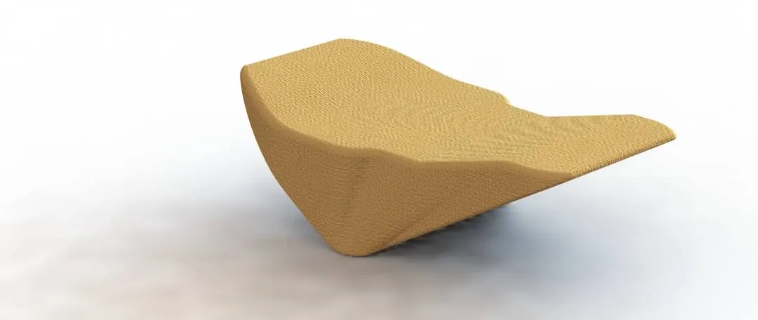
SEAT:
- Features Used:
- Lofted Surface
- Extruded Surface
- Trim Surface
- Knit Surface
- Chamfer
- Fillet
- Mirror
- Rendering:
- Features Used:
-
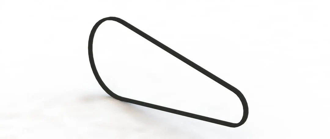
Transmission Belt: Transfers the Power from the Engine to the drive wheel of a bike, thus propelling it.
- Features Used:
- Extruded Boss
- Fillet
- Rendering:
- Features Used:
-
- ASSEMBLY:
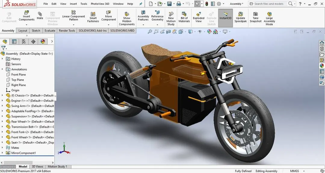
The parts that are designed are assembled. As said Chassis forms the base and fixed to the assembly. All other parts are mounted using appropriate mating conditions.
Mates Used:
- Coincident
- Concentric
- Width
- Parallel
- Angle
- Limit Angle
- Tangent
-
- Software Used:
- PHOTORELASTIC RENDERING:
-
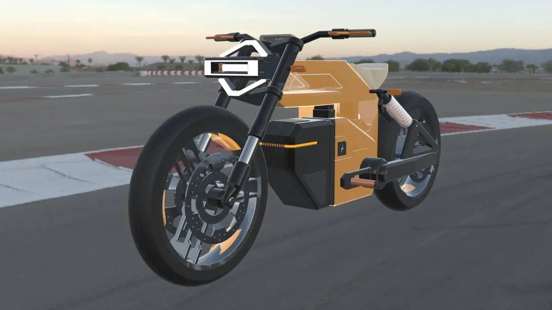
The Final Assembly Model is rendered using Visualize and using Photoview 360.
-
Different scenes were created by adding new camera views.
-
Visualize project is used to create relaistic environment and the rendereing is done.
-
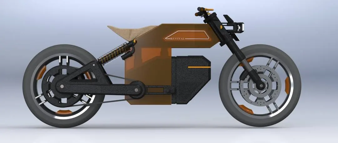
The rendered images are attached below with different environment and backgrounds.
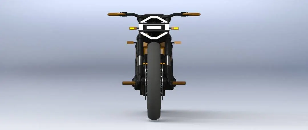
- Front View:
- Side View:
- Top View:
- Isometric View:
-
-
CONCLUSION:
- Thus a complete Electric Motorcycle is modeling using SOLIDWORKS, Photoview 360 & Solidworks Visualize.
- This project give me a understanding of how to create a model from blueprint to 3D model.
- The parts are assembled together to get a final model and I learn the different ways to assemble the parts by applying the different mates.
- The assembly was rendered in photoview 360 and solidworks visualize by using different environments.
- REFERENCES:
- Behance: Blueprint
- PROJECT PRESENTATION: PPT