DRAFT ANALYSIS OF A GIVEN CLASS-A SURFACING-FAN COVER
DRAFT ANALYSIS OF A GIVEN CLASS-A SURFACING-FAN COVER:
OBJECTIVE:
- The aim of the project is to carry Draft Analysis by creating the tooling direction for the given Class-A surface of the Fan Cover by using CATIA V5.
INTRODUCTION:
- The Draft Analysis command enables you to detect if the part you drafted will be easily removed. This type of analysis is performed based on colour ranges identifying zones on the analyzed element where the deviation from the draft direction at any point, corresponds to specified values.
- Tooling direction is the main consideration for plastic part and mould parts because it defines the movement of the mould part and the possibility of the plastic part coming out from the mould part (Core and Cavity).
What is Draft?
- Draft is providing angles or tapers on product features such as walls, ribs and bosses that lie parallel to the direction of release from the mold eases part ejection.
- Draft allows for the parts to release from the mold.
- Draft is required on all parts in the direction of mold movement in order to allow parts to release or eject form mold properly.
- Draft is the angle in which the parts is tapered to allow it to release. As the part cools, it tends to want to shrink to the core side of the mold.
- Adding draft helps the part to release. Most parts or applications require minimum of 1/2 to 1 degree, however 3 degrees is widely accepted as the norm.
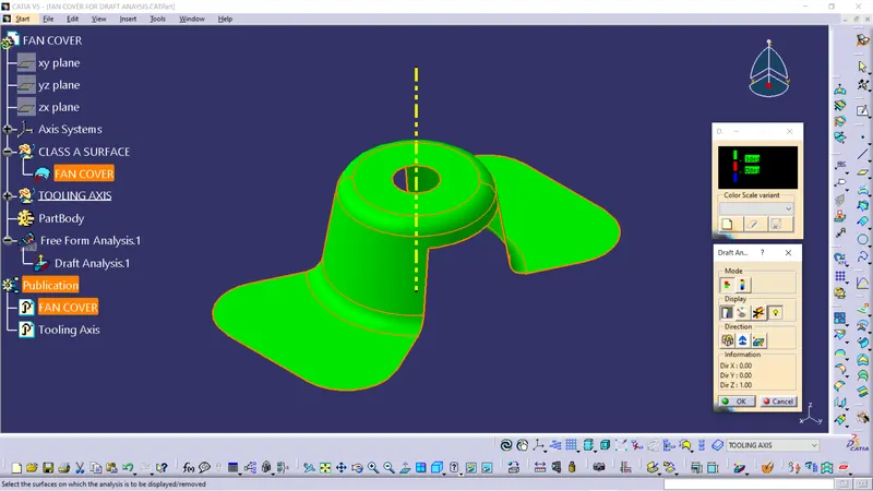
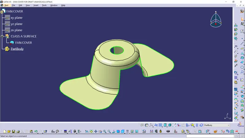
Given Class-A Surfacing:
PROCEDURE:
- Open the given CATPART and check for the gaps and boundaries of the component by using boundary option and selecting the whole component. any unwanted gaps in the model will be highlighted easily.
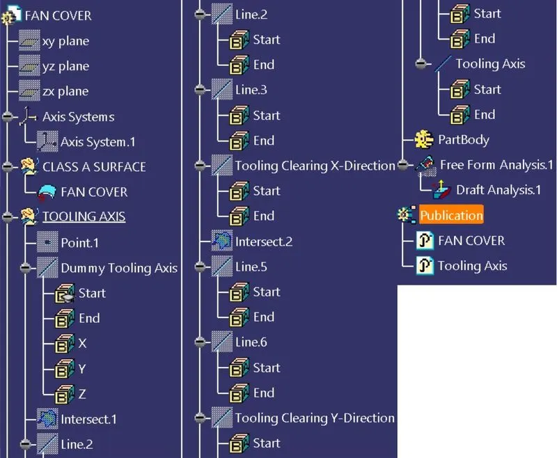
- The tooling axis needs to be created (the direction of the Mold input), perform all the operation in the separate geometrical set an name it accordingly.
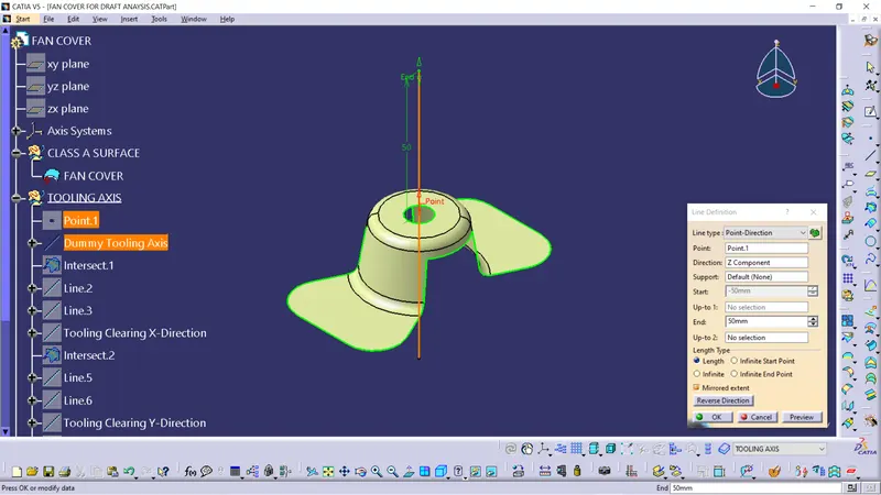
- Firstly, create a point in the desired location and between the hole in the component.
- Create a Dummy Tooling Axis with the center point in Z direction.
- Create a Axis using Axis option.
- Tooling Clearing X-Direction:
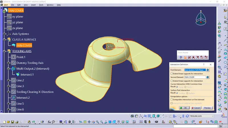
- Now using the intersection option select the component and the ZX-Plane to create a intersecting lines on the component. Make sure to keep all sub elements.
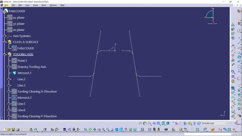
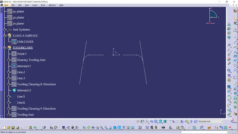
- Now with the reference on the intersecting lines create another lines using point-point option and extend them accordingly.
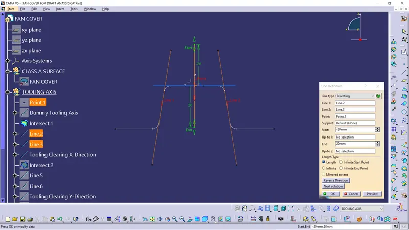
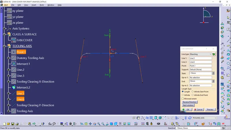
- Now create a bisecting- line with reference of the two newly created lines and point.
- Now using the intersection option select the component and the ZX-Plane to create a intersecting lines on the component. Make sure to keep all sub elements.
- Tooling Clearing Y-Direction:
- similarly follow the same procedure in creating another bisecting line for Y-Direction.
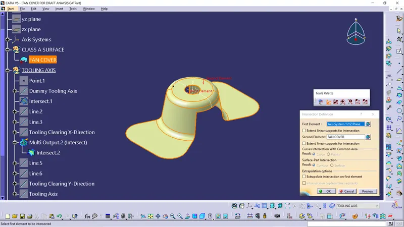
- Now using the intersection option select the component and the YZ-Plane to create a intersecting lines on the component. Make sure to keep all sub elements.
- Now with the reference on the intersecting lines create another lines using point-point option and extend them accordingly.
- Now create a bisecting- line with reference of the two newly created lines and point.
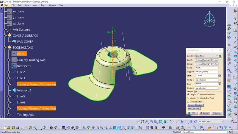
- Bisecting lines were used to get the exact medium from the two sides so that maximum positive draft angle can be achieved.
- Finally by using the bisecting line option the tooling axis were created by selecting the tooling axis x direction and y direction axis.
- Publication:
- The tooling axis and class-A surface were published for further easy reference.
DRAFT ANALYSIS:
- For plastic parts, the nominal angle value for draft analysis is 3 degree but even a 0.5-degree angle can be created for sub-assemblies like ribs and slots. (For Sheet Metal 7 degree angle is the nominal value)
- Insert - Analysis - Feature Draft Analysis.
- Draft analysis was carried out by pulling the compass to the tooling axis and an inverse draft axis was carried out if required.
- After setting the compass over the tooling axis the compass must be locked to a specific direction.
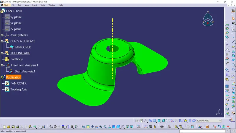
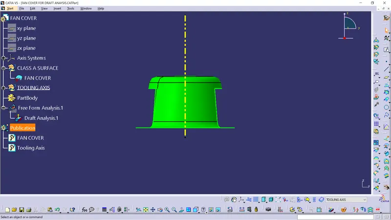
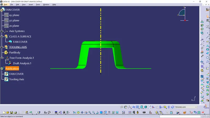
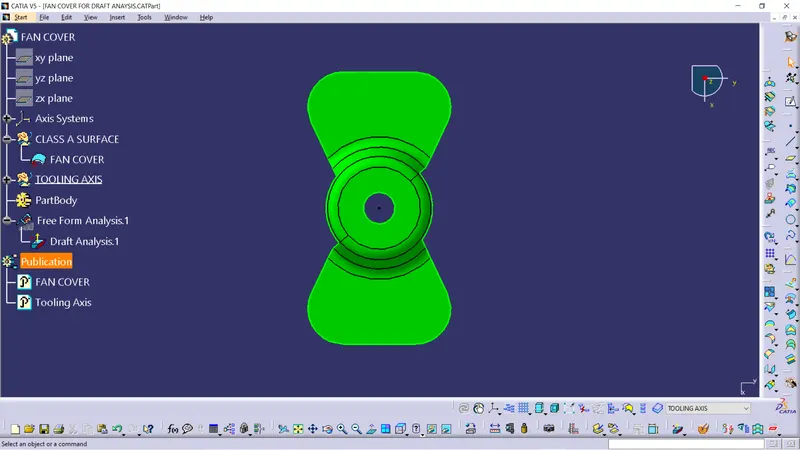
- If the surface was in green then the model passes or else further operations need to be carried out.
- Isometric View:
- Front View:
- Side View:
- Top View:
- Feature Tree: