CORE AND CAVITY DESIGN OF A GIVEN COMPONENT
CORE AND CAVITY DESIGN OF A GIVEN COMPONENT:
OBJECTIVE:
- The objective of the project is to create the class B and C surface for the Base bracket with the given Class-A surface to design a component and carry Draft Analysis by creating the tooling direction for the given Class-A surface.
- Then create a Core and Cavity of a created component.
DESIGN A COMPONENT USING B & C - SURFACE:
- Class-A Surface:
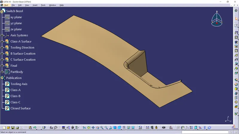
- It is the outermost surface of the automobile which gives aesthetic look to the vehicle. it is physically touchable. It is obtained from clay modelling by reverse engineering. This surface is given input to plastic product designer to work.
- It is the outermost surface of the automobile which gives aesthetic look to the vehicle. it is physically touchable. It is obtained from clay modelling by reverse engineering. This surface is given input to plastic product designer to work.
- Class-B Surface:
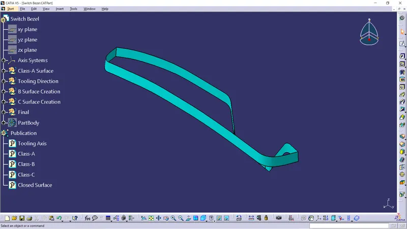
- This surface is created by taking offset of 2.5mm from class A surface. It is the surface on which all engineering feature like screw bosses, dog house, ribs & mounting are created.
- This surface is created by taking offset of 2.5mm from class A surface. It is the surface on which all engineering feature like screw bosses, dog house, ribs & mounting are created.
- Class-C Surface:
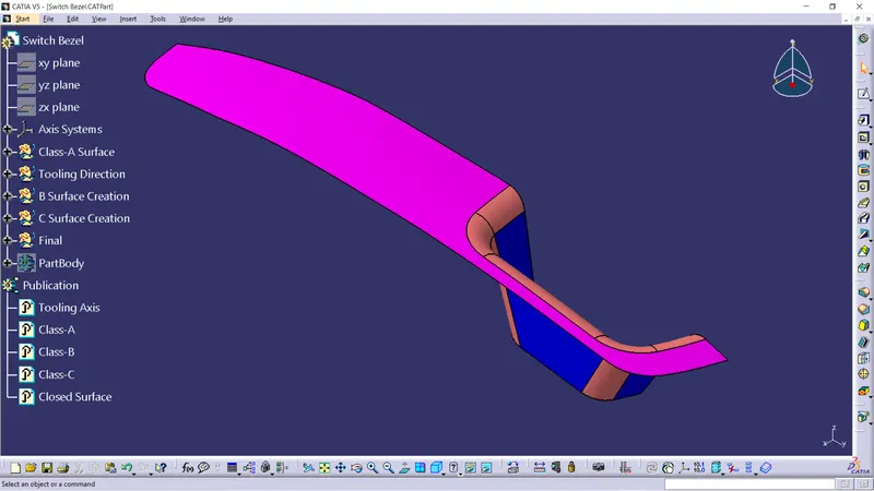
- This is the surface that joins class A & class B together.
- This is the surface that joins class A & class B together.
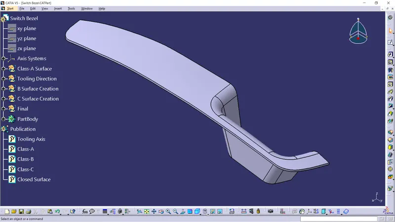
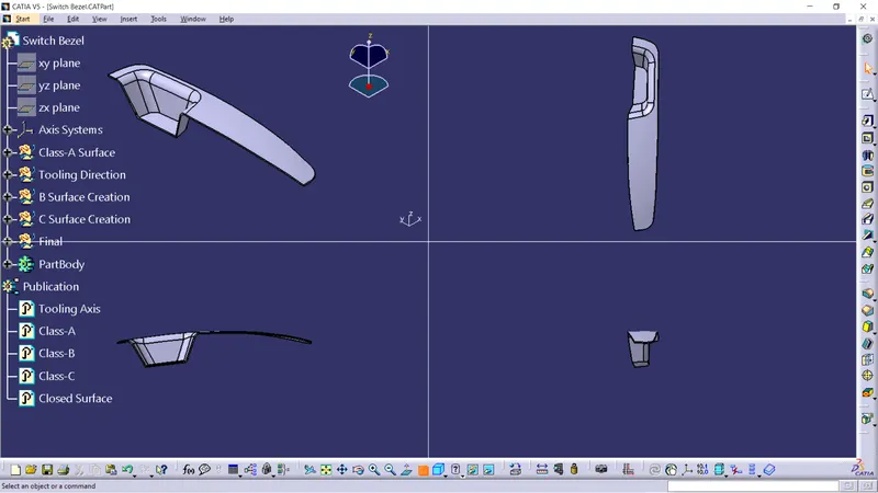
- Joining the Class A & C Surface
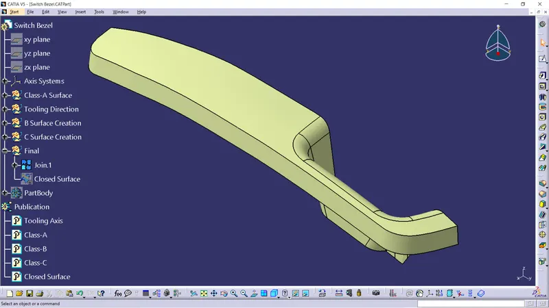
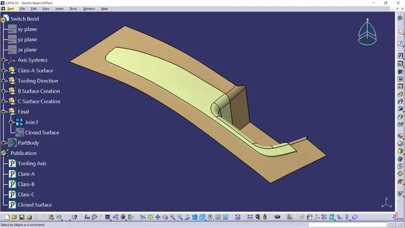
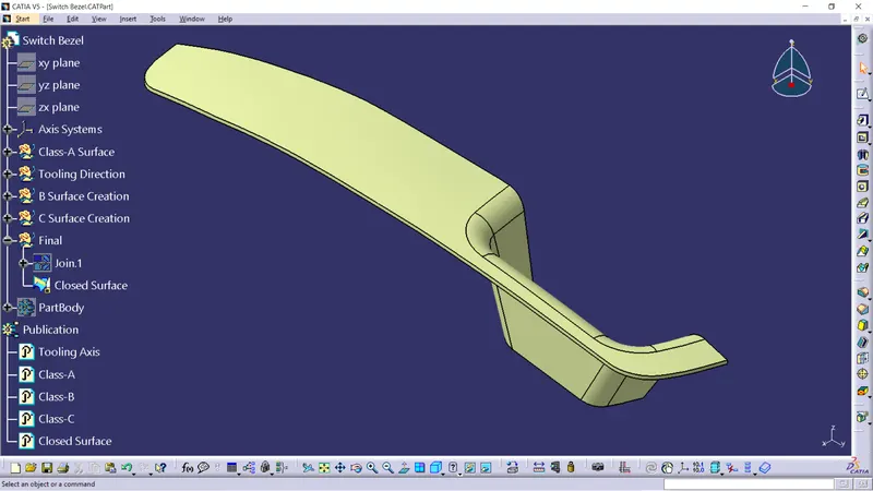
- Trimming the Class B & C surfaces and get the final trimmed base bracket closed surface
- Solid Model is created in part workbench by using Close Surface command
DRAFT ANALYSIS:
- INTRODUCTION:
- The Draft Analysis command enables you to detect if the part you drafted will be easily removed. This type of analysis is performed based on colour ranges identifying zones on the analyzed element where the deviation from the draft direction at any point, corresponds to specified values.
- Tooling direction is the main consideration for plastic part and mould parts because it defines the movement of the mould part and the possibility of the plastic part coming out from the mould part (Core and Cavity).
- What is Draft?
- Draft is providing angles or tapers on product features such as walls, ribs and bosses that lie parallel to the direction of release from the mold eases part ejection.
- Draft allows for the parts to release from the mold.
- Draft is required on all parts in the direction of mold movement in order to allow parts to release or eject form mold properly.
- Draft is the angle in which the parts is tapered to allow it to release. As the part cools, it tends to want to shrink to the core side of the mold.
- Adding draft helps the part to release. Most parts or applications require minimum of 1/2 to 1 degree, however 3 degrees is widely accepted as the norm.
- DRAFT ANALYSIS:
- For plastic parts, the nominal angle value for draft analysis is 3 degree but even a 0.5-degree angle can be created for sub-assemblies like ribs and slots. (For Sheet Metal 7 degree angle is the nominal value)
- Insert - Analysis - Feature Draft Analysis.
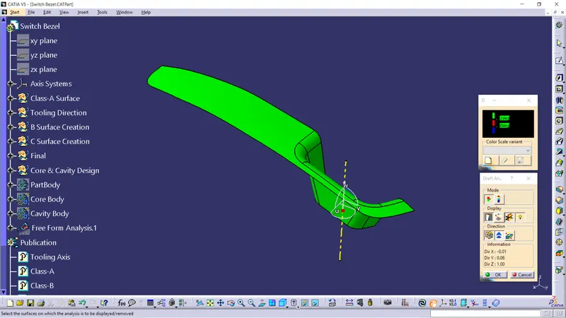
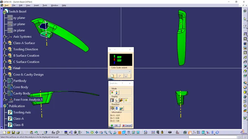
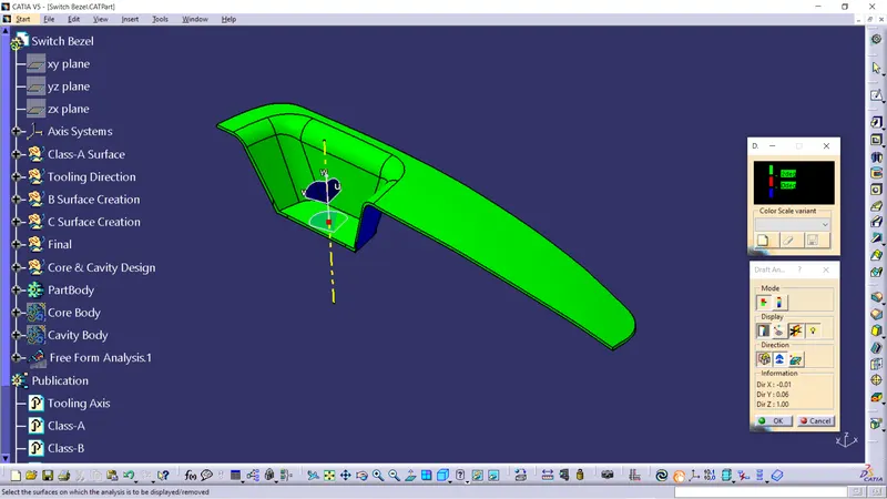
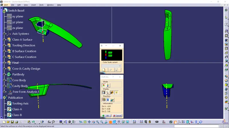
- Draft analysis was carried out by pulling the compass to the tooling axis and an inverse draft axis was carried out if required.
- After setting the compass over the tooling axis the compass must be locked to a specific direction.
- If the surface was in green then the model passes or else further operations need to be carried out.
- PROCEDURE:
- First the class - A surface is checked before creating the Class-B&C surface and finally the solid body must be analysed. Both can be done by following the below procedures.
- By changing the view mode to custom view parameters - Material mode then the feature draft analysis is enabled.
- Then the compass was activated and placed with the tooling axis by dragging the red pointer and then locked it.
- Then, by selecting the quick analysis mode, the nominal value will be 3 degrees and checked for the component's draft angle.
- The green colour area shows that it satisfies the 3-degree draft angle. If not satisfied then by using the Running point tool the area is measured and then altered to get a successful draft for the created tooling direction.
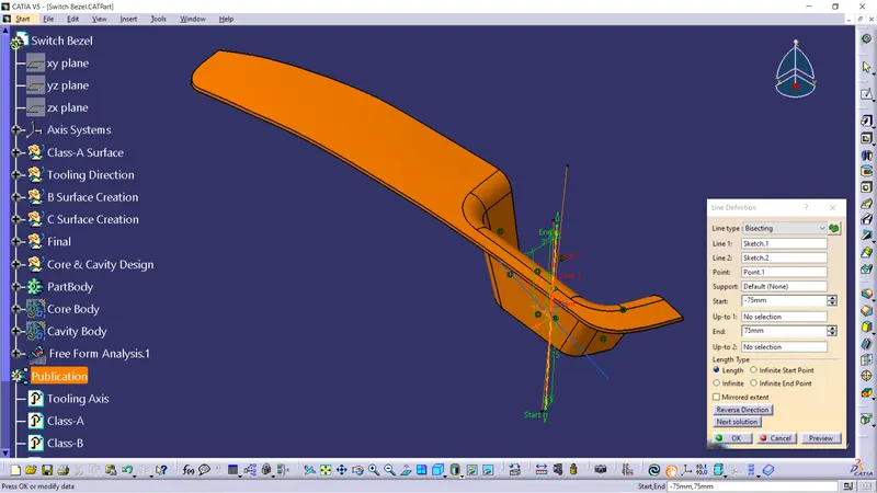
- CREATION OF TOOLING AXIS USING THE BISECTING METHOD:
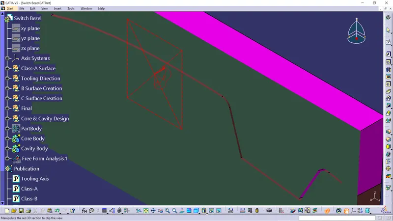
- The first thing to do is to find the possible tooling direction by visually checking the part. Rotate the part in all directions and find out the most suitable direction for tooling. Here in this case viewing from Z direction we can clear the face in tooling.
- Then a point on the surface of the part was created, we can create the point anywhere on the surface but usually, we take CG point or take a point near to the centre. On this point, we put a new axis system.
- Then, finding the X direction tooling axis by using the intersect command the boundary in the X direction or XZ plane has been projected. The draft line is draw in the XZ plane.
- Then, finding the Y direction tooling axis by using the intersect command the boundary in the Y direction or YZ plane has been projected. The draft line is draw in the YZ plane.
- Bisecting lines were used to get the exact medium from the two sides so that maximum positive draft angle can be achieved.
- Finally by using the bisecting line option the tooling axis were created by selecting the tooling axis x direction and y direction axis.
- Draft Analysis of a CLass A Surface with Tooling Axis:
- Draft Analysis of a Solid Part Body with Tooling Axis:
- CREATION OF TOOLING AXIS USING THE BISECTING METHOD:
CORE AND CAVITY DESIGN:
- INTRODUCTION:
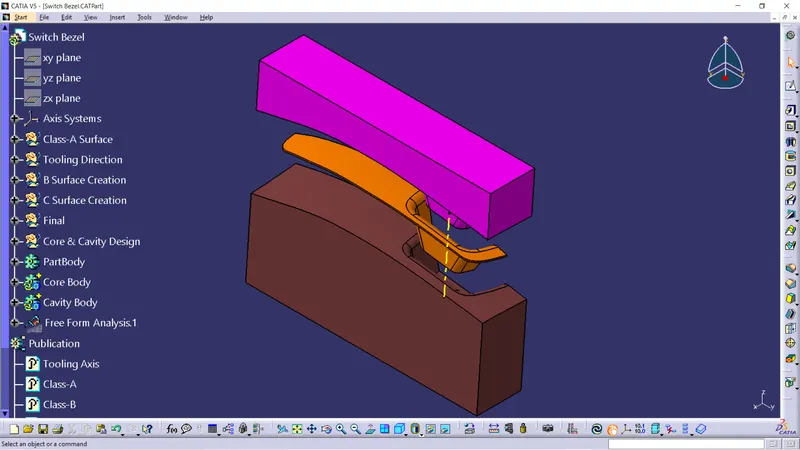
- The plastic parts were usually manufactured with forming process particularly Injection molding process. In the forming processes the part is formed between two or more dies based on the geometry of the part. In forming processes vacant space is left between the dies which is same as the geometry of the part then the space is filled with the molten material on which the part is intended to manufacture. In injection moulding process basic die consists of core and cavity. When the molten plastic is injected into the space between the core and the cavity the injected plastic gets frozen, and part is formed. Core will be the one half of the die which has projection in it and the cavity will have the hollow space on the cavity block.
- The core and the cavity will move along the tooling direction. Generally, core will be the moving part and the cavity will be the fixed half through which the molten plastic is injected into the mold. The core and the cavity will be separated by the parting surface.
- CORE:
- The core is the convex region (also called the male part of the mold), which forms the inner surface of the component which is being molded.
- Movable side molds (mold) made the convex shape.
- Mold closes the cavity and core can make the geometry of the combined product.
- The resulting space is called 'cavity'.
- Core Design of Switch Bezel:
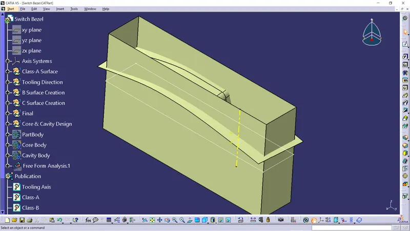
- Parting surface of the Core is created by trimming the Class A and C with B surface.
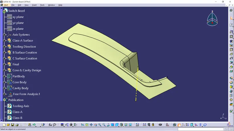
- Then a block is created by extruding the rectangle along the tooling direction. As shown in the figure below.
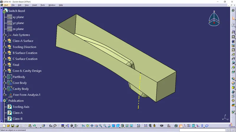
- Then this rectangle is trimmed with the parting surface and the rectangular surface which is created.
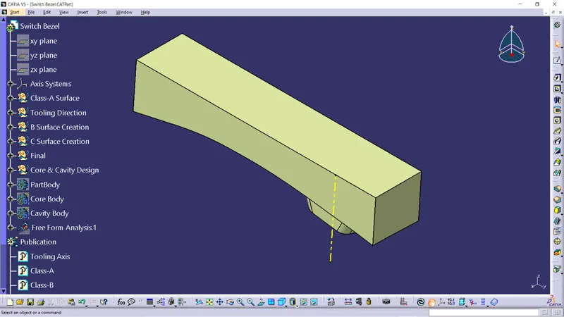
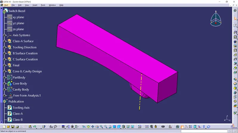
- Then the top of the surface is closed by using Fill command and this shell is converted into a solid by using the Closed Surface command in Part Design.
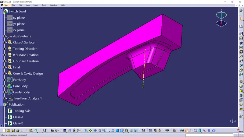
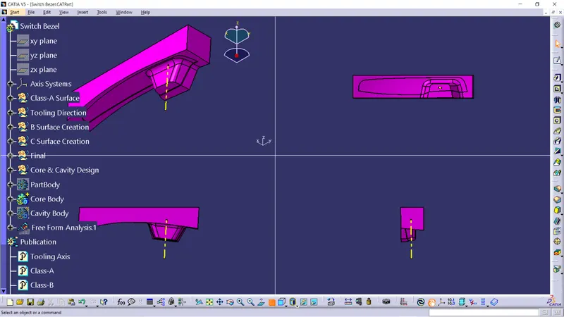
- Core Design of Switch Bezel:
- CAVITY:
- The cavity is the depression or the concave region (also referred to as the female portion of the mold) and forms the component's outer surface.
- Molten plastic to enter the fixed side (mold) its made the concave space.
- Mold cavity referred to having a the cavity mold tooling.
- Fixed side mold cavity molds.
- Cavity Design of Switch Bezel:
- Parting surface of the Cavity is created by Class B surface.
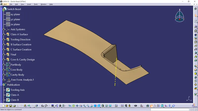
- Then a block is created by extruding the rectangle along the tooling direction. As shown in the figure below.
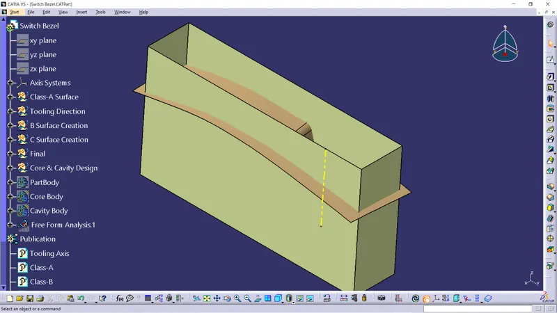
- Then this rectangle is trimmed with the parting surface and the rectangular surface which is created.
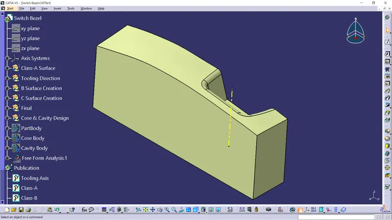
- Then the buttom of the surface is closed by using Fill command and this shell is converted into a solid by using the Closed Surface command in Part Design.
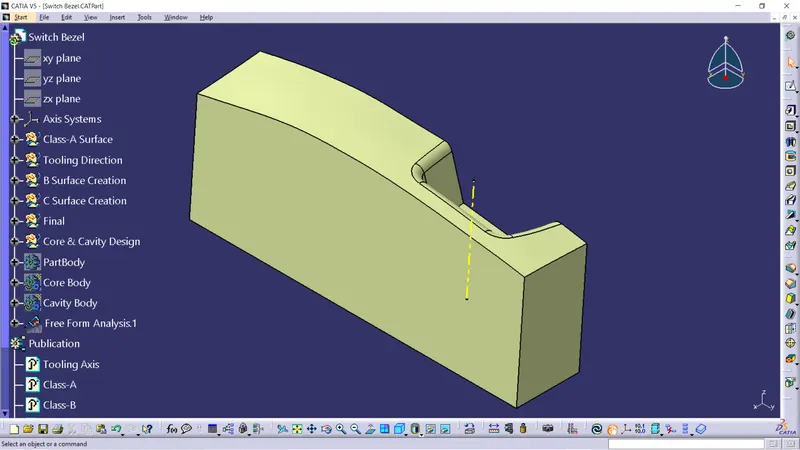
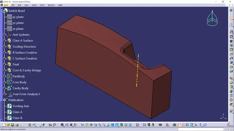
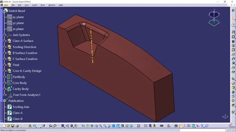
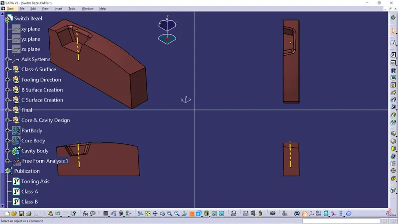
- Cavity Design of Switch Bezel: