Wiring harness design in CATIA V5 - 3D modeling Week 2 Challenge
In this Challenges we have create a Catalog and add the Electrically defined parts in the Catalog:
- What is a Catalog Document?
A catalog is a CATIA V5 document that keeps a list of references to other CATIA parts and features. In a wiringharness it means that we can store a set of electrically defined parts(like Connectors, Clamps, Clips etc.)in a document and insert into product assembly whenever they are required. - PROCEDURE FOR CREATING CATALOG DOCUMENT:
- When a CATIA software is started.
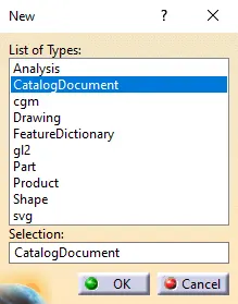
Click on File > New > In List of Types : Catalog Document, a small window like below pops up where the highlighted bluecoloured selection (Catalog Document) has to be selected. -
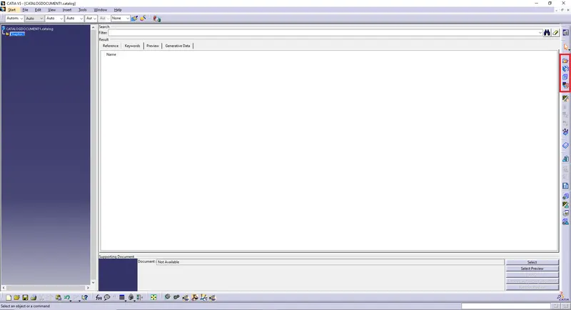
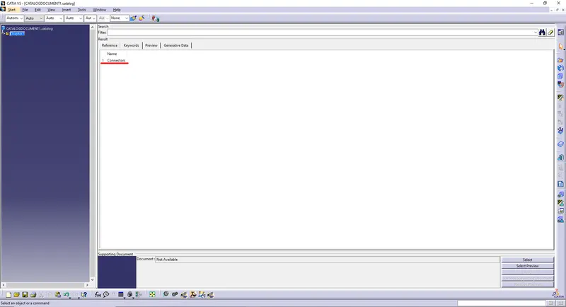
A new window opens up as shown below.
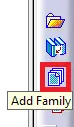
Towards right of the window you can find highlighted tab (chapter). - As shown in above tab select the Icon - add family.
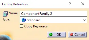
- Clicking on the above Icon > a small Family Definition window opens up.
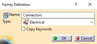
- So in this we are considering the creating a Connectors Catalog creation so in
Name > Connectors
Type > Electrical
At last, Click on OK.
- Family name : Connectors is created, shown below.
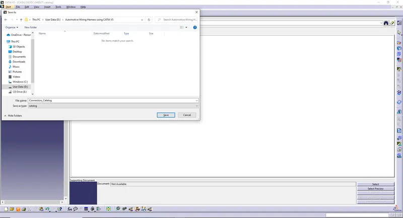
- For saving the file, press Ctrl + S on the keyboard and name it as Connectors_Catalog.
- Close the Catalog document created.
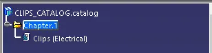
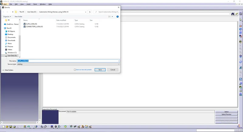
- Similarly create another catlog for Clips named as Clips_Catalog.
- When a CATIA software is started.
- DEFINING THE PARTS ELECTRICALLY:
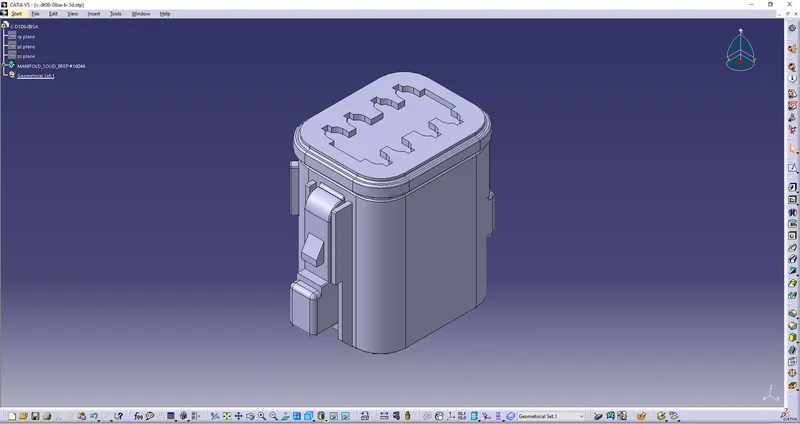
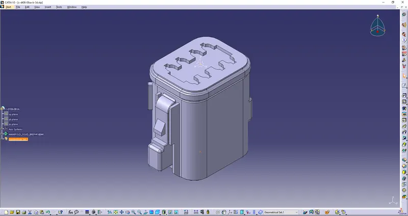
- Downloaded the Connectors Part from te.com.
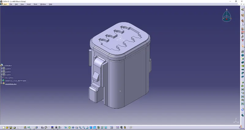
- Define the Point and Axis Sysytem.
- Switch into Electrical Part Design.
- Define a part as connector.
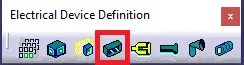
- For defining part as a Connector under Electrical Device Definition we have to select the connector.
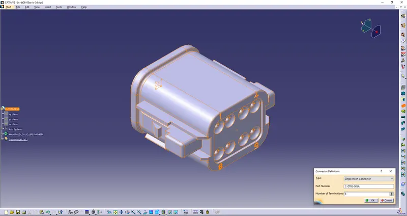
- Clicking on the above Icon > a small Connector Definition window opens up.
So in this we a defining the part as Electrically
Type > Single Insert Connector
No. of Terminations > 8 (Based on the Terminal Ports)
At last, Click on OK. - After defining the part electrically then we has to define the following:
- Connector Connection Point: This point is used for the connection of one connector to another connector.
- Harness Bundle Entry Point: This point defines where the harness bundle segment point will end when routed to the electrical connector.
- Cavity Connection Point (Optional): This point is used to define the connection of a connector to a connector clip. This only applies to connectors which have the mounting feature for a connector clip.
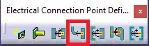
- For defining a Harness Bundle Entry under Electrical Connection Point Definition we have to select the Bundle Connection Point.
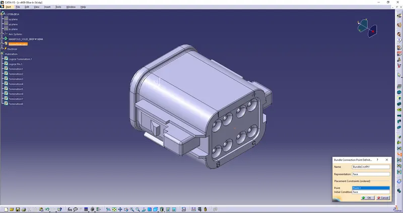
- Clicking on the above Icon > a small Bundle Connection Point window opens up.
So in this we a define the Bundle Connection Point
Representation >
Point >
Initial Condition >
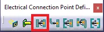
At last, Click on OK. - For defining a Connector Connection Point under Electrical Connection Point Definition we have to select the Connector Connection Point.
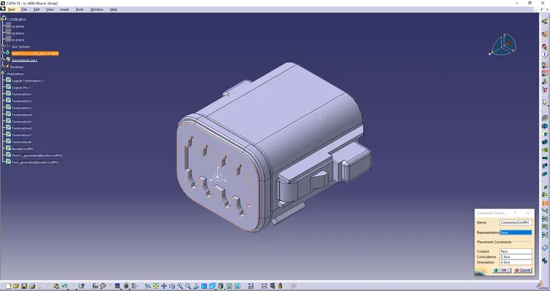
- Clicking on the above Icon > a small Connector Connection Point window opens up.
So in this we a define the Connector Connection Point
Representation > (Connector Connection Point)
Contact > (Connector Mating Face)
Coincidence > (Coincidence Axis)
Orientation > (Orientation Axis)
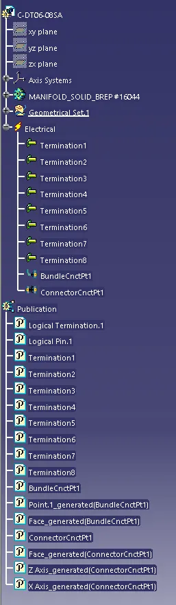
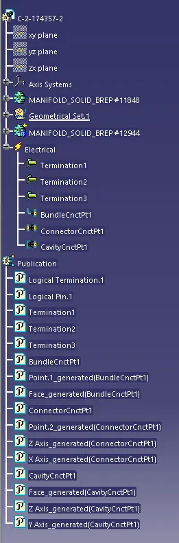
At last, Click on OK. - Here is the tree structure.
- Finally save the electrically defined part.
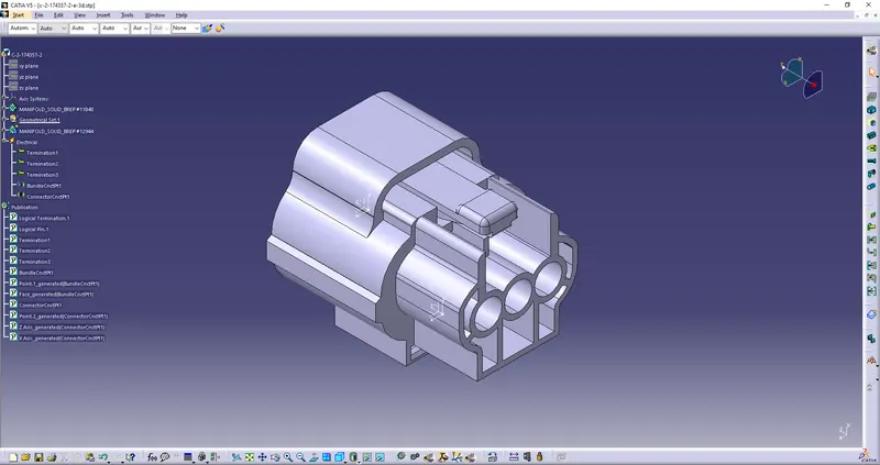
- For another part from (step1 - step13) the same way for other Connector in this we additionally add Cavity Connection Point.
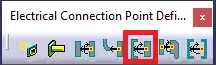
- For defining a Cavity Connection Point under Electrical Connection Point Definition we have to select the Cavity Connection Point.
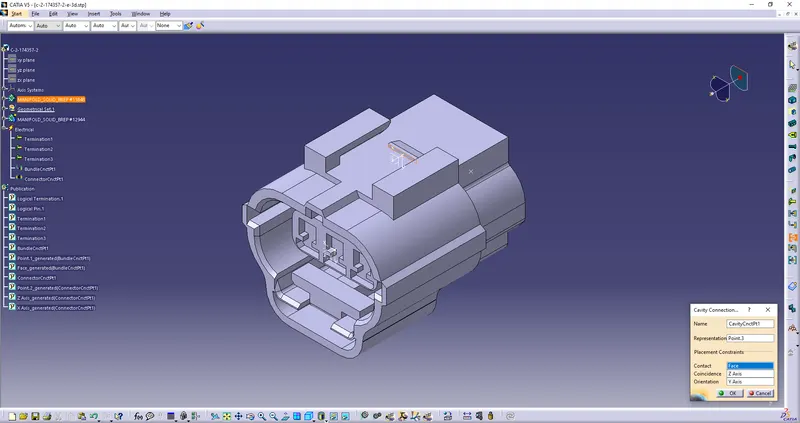
- Clicking on the above Icon > a small Cavity Connection Point window opens up.
So in this we a define the Cavity Connection Point
Representation > (Cavity Connection Point)
Contact > (Cavity Mating Face)
Coincidence > (Coincidence Axis)
Orientation > (Orientation Axis)
At last, Click on OK. - Here is the tree structure.
- Finally save the electrically defined part.
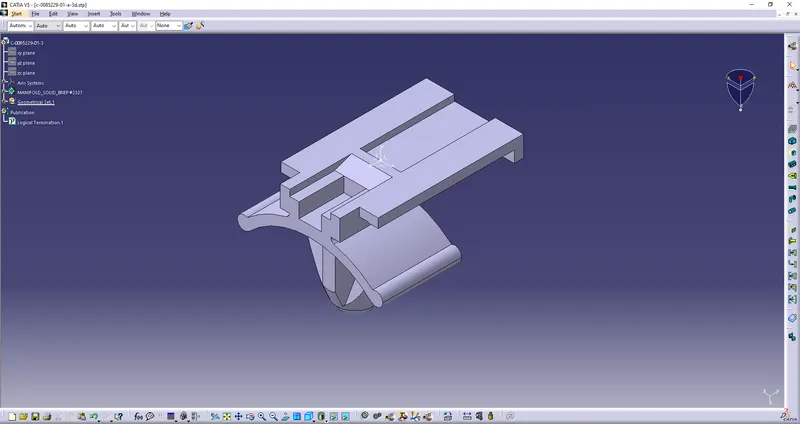
- Define another part as a Mounting Equipment and define the Cavity.
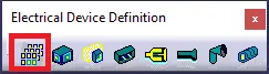
- For defining part as a Mounting Equipment under Electrical Device Definition we have to select the Mounting Equipment.
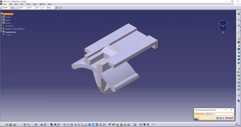
- Clicking on the above Icon > a small Mounting Equipment Definition window opens up.
Click on OK.
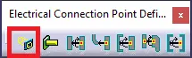
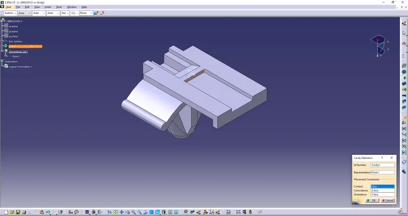
- For defining a Cavity under Electrical Connection Point Definition we have to select the Cavity.
- Clicking on the above Icon > a small Cavity Connection Point window opens up.
So in this we a define the Cavity Connection Point
Representation > (Cavity Connection Point)
Contact > (Cavity Mating Face)
Coincidence > (Coincidence Axis)
Orientation > (Orientation Axis)
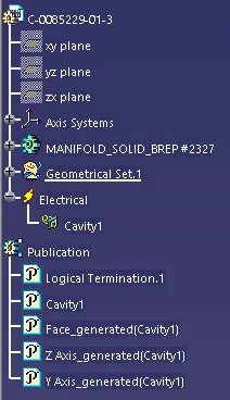
At last, Click on OK. - Here is the tree structure.
- Finally save the electrically defined part.
- Downloaded the Connectors Part from te.com.

- ADDING THE ELECTRICALLY DEFINED PART IN CATLOG:
- In the same window there is a symbol
 called a storage device where we can store the various Connectors, Clips, Clamps etc.
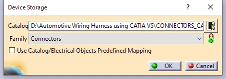
 - Selecting the above icon we have to add the Connectors to the Connectors_Catalog document - By clicking on the Icon shown below, navigate to the path where the Connectors_Catalog document is saved, also select the family (Connectors) which was created in step 5. Finally, Click OK , where the Connectors_Catalog is saved in Catalog.
-
- Similarly we add n number of Connectors, Clamps, Clips etc. are saved to the Catalog document.
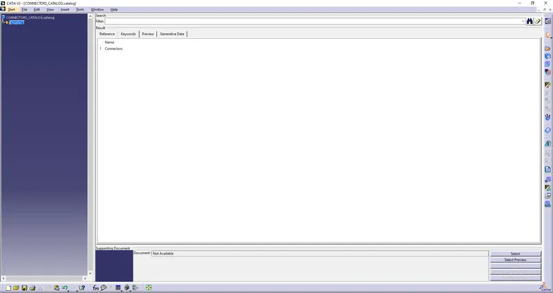
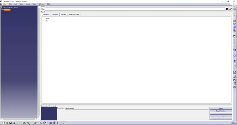
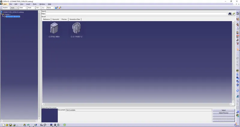
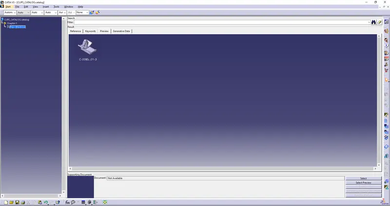
- To check whether all the Connectors & Clips are added into the Catalog,do follow the steps below.
- Navigate to the Connectors_Catalog & Clips_Catalog in the folder and open it in CATIA software.
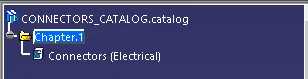
- Expand the chapter 1, Where the Connectors & Clips saved will open.
- Double Click on the Connectors & Clips in the feature tree, navigate & click on to the preview tab to view the Connectors & Clips saved in the Connectors_Catalog & Clips_Catalog document.
- Navigate to the Connectors_Catalog & Clips_Catalog in the folder and open it in CATIA software.
- In the same window there is a symbol