Fender Design Challenge
Aim:
To prepare Drip Area from the given master section and to create Sill, Bumper, Baffle(Splash), and A-Pillar mount as per standard.
Input Given:
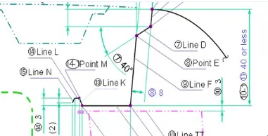
Master Section of Drip region:
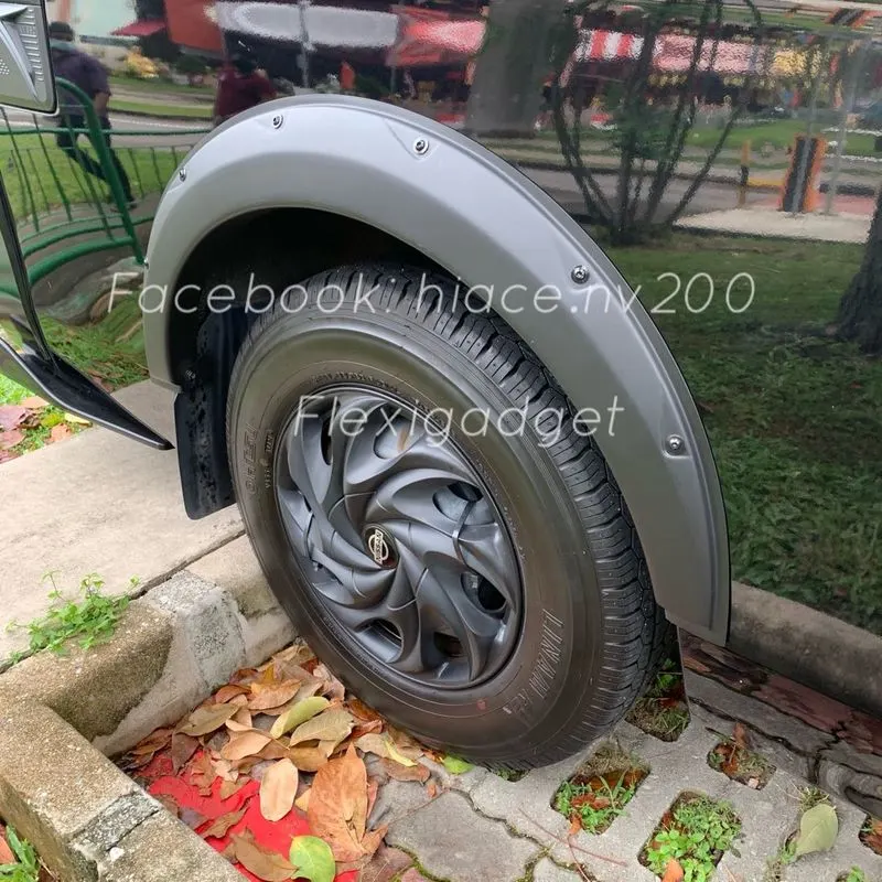
Fender:
Fender is an part the Body which primary purpose is to prevent sand, mud particles, rocks which is carried out and thrown in a direction due to the kinetic energy developed by the tires. Its basic purpose is to prevent any injuries to pedestrians and contain motion of particles to engine cabin.
Two types of fender
- Full bumper
- Half bumper
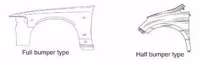
Half bumper type is commonly used now due to material saving and weight saving which is an important factor for fuel economy.
Mounting Points :
The fender is mainly mounted in following ,
- Bumper mount area.
- Drip region mounting
- A pilllar mount Region
- sill mounting region
The mounting can be done using fastners as these parts would not be visible outside.
The mounting region design is very important in order to hold the part with mating part and to withstand forces.
The main aim of fender is to protect engine cabin and pedestrian safety, if the moving vehicle throws the stone or some foreign particle,
it might hit a pedestrian and cause injury. To avoid this there are various regulation designed that the gap between wheel arch and edge of wheel should be of minimum 5mm as per European regulation and the minimum gap varies for different regulation of different countries.
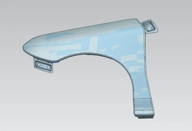
Drip Region:
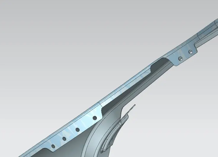
The drip region is created based on the master section provided, the drip region is used to mount the fender in the engine cabin, the position of drip is very important as we need clearence from the front and rear side. this clearence is mainly because infront the headlight projection and corresponding mountings are provided and the clearence is required, its normally around 150mm, and in rear side the wiper motor is fixed , inorder to mount it,the necessary clearence is provided near cowl, normally around 200mm and max 300mm mostly.
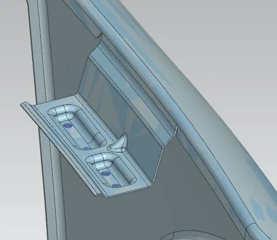
Based on master section, the first draft of 3° is provided for easy ejection of tool and the next of 40° is provided inorder to obstruct the direct view of cabin to customer,it would be weird, this inclination will obstruct the view and the next 5° and total length is maintained as per master section. this drip region is created using law extension with necessary dimensions. and an additional dart is created in the surface to improve strength.The edge region of drip with u shape is created using the face blends with necessary lengths and the three surfaces has been face blended with dimension as per master section. The edges have been blended using the edge bend tool with necessary radius as in master section.
The depth of the drift should be between 40 to 60mm. If the depth exceeds from 60mm then forming is not feasible due to spring back and wrinkles.Embosses and ribs are given to drip area to improve strength.
These are the major dimensions which has been given in master section and completed , the other mounting regions are A-Pillar , baffle,sill, bumper.
A-Pillar mounting:
A-pillar is the point of reference used to indicate the name of the pillar on which the both the sides for front windshield is fixed, following which the B,C Pillars has been named.
in fender design the rear end of the fender is mounted with the A-pillar, in the designed fender , the A-pillar mounting region is created using Law of extension tool and extended to 40 mm and corresponding embossing is created to improve strength with edge blends in emboss, the sketch has been made in datum plane and project curve tool is used to project curve on the flange created for pillar mounting. and the hole is created in the embossed faces using the trim sheet tool. This mounting is done using fasteners. The edges betweeen the A pillar mounting and the flange in fender is blended with minimum radius using face blend tool and the excess edges of blend has been trimmed off using the bridge curve or trim sheet command.
Sill mounting Region:
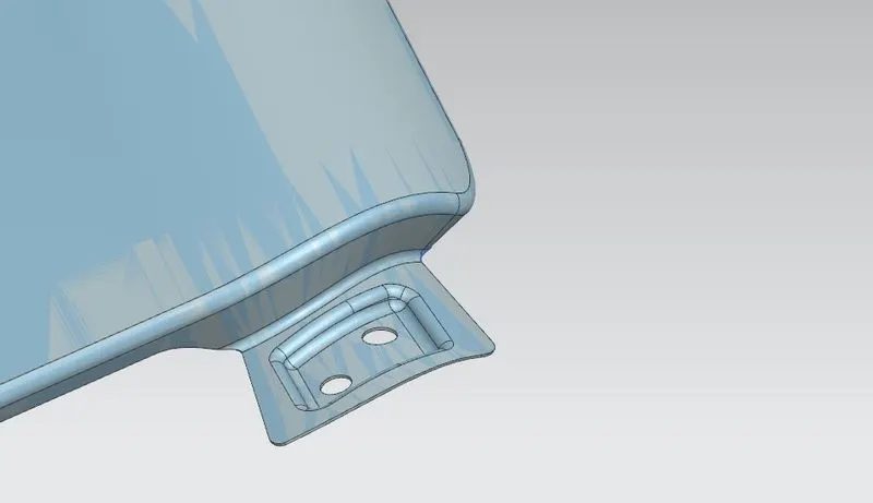
Sill mounting region is the bottom side of fender, which is used to mount parallel to the front doors. The fender is fastened using fasteners as its invisible and covers inside. The edges have created and made a smooth surface wherever required using curve on surface command and Trim sheet to trim off the unneccesary support. the flange is created using the extend sheet command and its extended to 40mm and the corresponding sketch has been made and the emboss is created and the hole is made using trim sheet for mounting.
Bumper mounting:
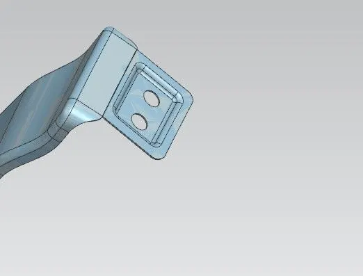
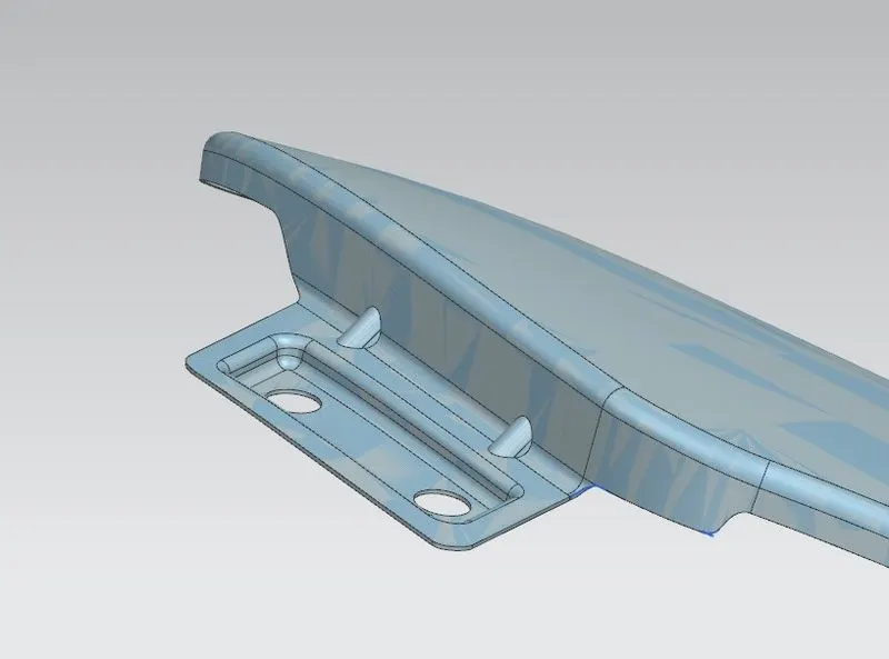
Bumper is the horizontal part fixed connecting both sides , and fixed front and rear of the vehicle , which is used to absorb in front of collision. this is created very similar to A-pillar mounting, in addition we have created additional darts in the bumper mounting to increase the strength. mounting region is created using Law of extension tool and extended to 40 mm and corresponding embossing is created to improve strength with edge blends in emboss, the sketch has been made in datum plane and project curve tool is used to project curve on the flange created for bumper mounting. and the hole is created in the embossed faces using the trim sheet tool. This mounting is done using fasteners. The edges betweeen the A pillar mounting and the flange in fender is blended with minimum radius using face blend tool and the excess edges of blend has been trimmed off using the bridge curve or trim sheet command, the additional ribs are created using dart tool and the angle and depth is fixed ,considering the sufficient gap is provided between emboss edges and the rib edges, considering the manufacturing feasibility.,
Baffle or splash mounting:
To increase the efficiency of NVH, the baffle is provided, inorder to mount it, the hole has been created directly in the flanges, the baffle mounts are created in two sets in the arch region , the hole is created using the trim sheet command.
Production Process:
The manufacturing process firstly, unfolding the sheet metal from roll.
Shearing is carried out on a plate- ie the process of cutting metal into sizes.
Then the oil pressing and punching are carried out, wherein the iron plate is extended at first, then side shearing and punching are conducted on the iron plate.
Folding and shaping is done as necessary
Finally reshaping is carried out on the iron plate.
the iron plate is punched to a needed outer contour blank,
The manufacturing process for the car fender is simple and high in production efficiency.
Conclusion:
The fender drip mounting region has been created as per master section provided and the other mounting regions has also been designed as per requirements.