Section Modulus calculation and optimization
Aim:
To use the Section from Hood design and calculate the Section Modulus and to create a new section that has an improved Section Modulus compared to the previous one and mention what changes you made which resulted in the increased strength.
Section Modulus:
Its defined as the ratio of moment of inertia of a section about its centroidal axis to the distance of the extreme fiber form the neutral axis.
Z= I/Y
Where I is moment of inertia
Y is distance of extreme fibre from the neutral axis.
(I)-Moment of inertia: Moment of inertia of a cross section of beam is the measure of stiffness of beam. The higher the moment of inertia, the lesser would be the deflection of beam in load condition, its a cross section property that is inversly proportional to the deflection of beam.
Its also called as second moment of area, area moment of inertia and in torsional its called as polar moment of inertia. It can also be defined as , The sum of the second moment of area of all the infinitesimally small
areas of the cross section about the centroidal axis of the cross section.
The section modulus varies depending on the cross section of the part, the basic shapes are of as follows, which is derived already.
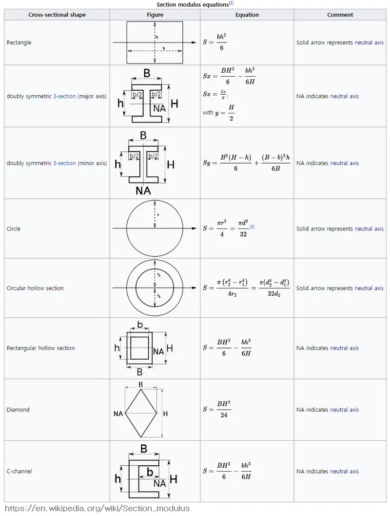
The above are few basic shapes, which is used to calculate S.
Considering the front hood design, The middle region has been used as a cross section of hood and corrresponding section modulus has been found as follows,the outer panels puter region has been taken and the inner panels outer region has been taken, and the two has been sketched and connected to form a closed cross section of area.
The Moment of inertia has been calculated using a tool called section inertia analysis in NX.to activate the section inertia analysis ,the sketch has to be of closer section as a basic requirement.
Case 01:
The actual hood design has been taken without any modification in cross section and corresponding Section modulus is calculated as follows, here our aim is to improve the minimum strength.The cross section has been created and the section modulus is calculated as follows,
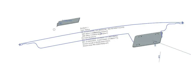
in the above cross section the Moment of inertias are
M(Max)-1.6088*10^7 mm^4
M(Min)-1.9790*10^5 mm^4
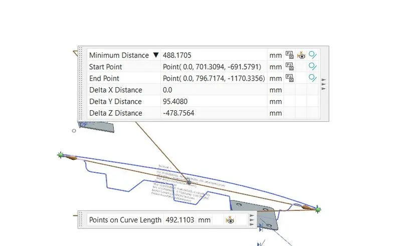
and the distance (y) is 492.11/2= 246.05
S=I/Y
Moment of inertia minimum is considered,
s=1.9790*10^5 mm^4 divided by 246.05 mm
= 1.9790*10^5 mm^4 / by 246.05 mm
=804.30 mm^3.
Lets consider Section modulus for case 1 as S1 =804.30mm^3.
Case 2 :
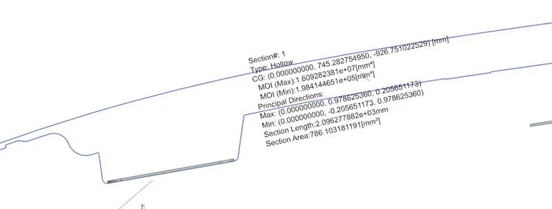
in case 2, the cross section has been varied slightly by creating a offset by 0.5mm , like an emboss in the inner panel and corresponding results are as follows.
in the above cross section the Moment of inertias are
M(Max)-1.6092*10^7 mm^4
M(Min)-1.9841*10^5 mm^4
nd the distance (y) is 492.11/2= 246.05
S=I/Y
Moment of inertia minimum is considered,
s=1.9841*10^5 mm^4 divided by 246.05 mm
= 1.9841*10^5 mm^4 / by 246.05 mm
= 806.38 mm^3
Lets consider Section modulus for case 2 as S2 =806.38 mm^3.
Case 3 :
in case 3, the cross section has been varied slightly by creating a offset by 1mm , like an emboss in the inner panel and corresponding results are as follows.
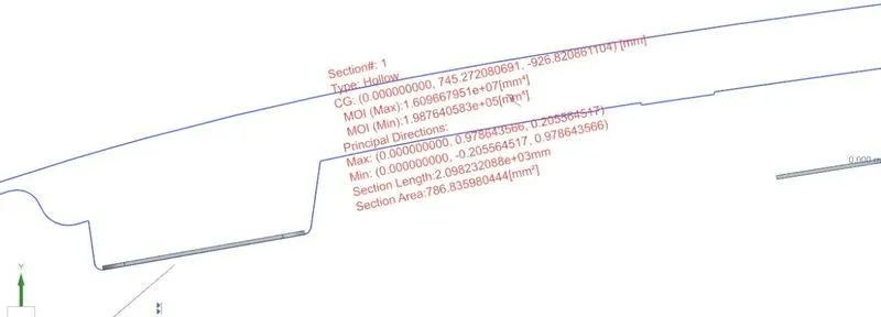
In the above cross section the Moment of inertias are
M(Max)-1.6096*10^7 mm^4
M(Min)-1.9876*10^5 mm^4
nd the distance (y) is 492.11/2= 246.05
S=I/Y
Moment of inertia minimum is considered,
s=1.9876*10^5 mm^4 divided by 246.05 mm
= 1.9876*10^5 mm^4 / by 246.05 mm
= 807.80 mm^3
Lets consider Section modulus for case 3 as S3 =807.8 mm^3.
Case 1=Section of modulus S1- 804.30 mm^3.
Case 2=Section of modulus S2-806.38 mm^3.
Case 3=Section of modulus S3-807.80 mm^3.
Conclusion:
When we compare the three sections,
a) the case 3 is better than case 2 and 1.
b) the case 2 is better than 1.
This shows that the varying in design ie in cross section ,the corresponding moment of inertia increases and that improves the section modulus. This helps in improving strength.
----------------END-------------------
Case 4 only for study (x):
Other than this also tried to create an emboss similar to the striker region and checked for the section modulus of the same.
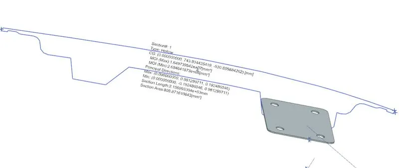
In the above cross section the Moment of inertias are
M(Max)-1.6497*10^7 mm^4
M(Min)-2.6946*10^5 mm^4
nd the distance (y) is 492.11/2= 246.05
S=I/Y
Moment of inertia minimum is considered,
s=2.6946*10^5 mm^4 divided by 246.05 mm
=2.6946*10^5 mm^4 / by 246.05 mm
= 1095.14mm^3
Lets consider Section modulus for study (X)=1095.14 mm^3.
When we compare the case 01 and the studY(X) the section modulus has improved drastically from 804.30 to 1095.14 mm^3, as in front hood panel, this new cross section might not be feasible, we didnt consider, this is done just for section modulus study.