Week 8 - Challenge 1 - Base Bracket Design
Aim:
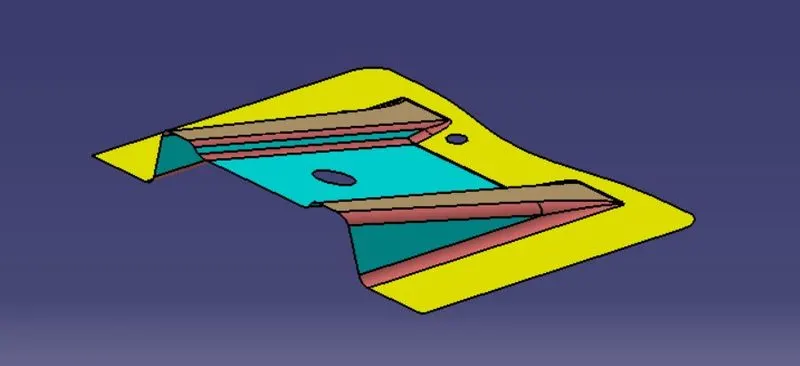
To Create the Base Bracket Plastic component through the given Class-A surface. To begin with, the tooling axis for the given Class-A Surface should be created meeting the requirements of the draft angle and at the end perform the Draft analysis on the model.
Procedure:
The base bracket design is to be carried out using the given class A surface.
Tooling axis:
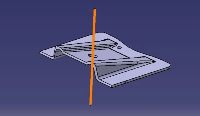
First intially created a dummy tooling axis along z axis in class A surface for intial draft analysis and checked,
then the overall shape is considered and the slope is considered and corresponding bisecting line near hole and plane is created. The new tooling axis line is created from the two bisecting lines.
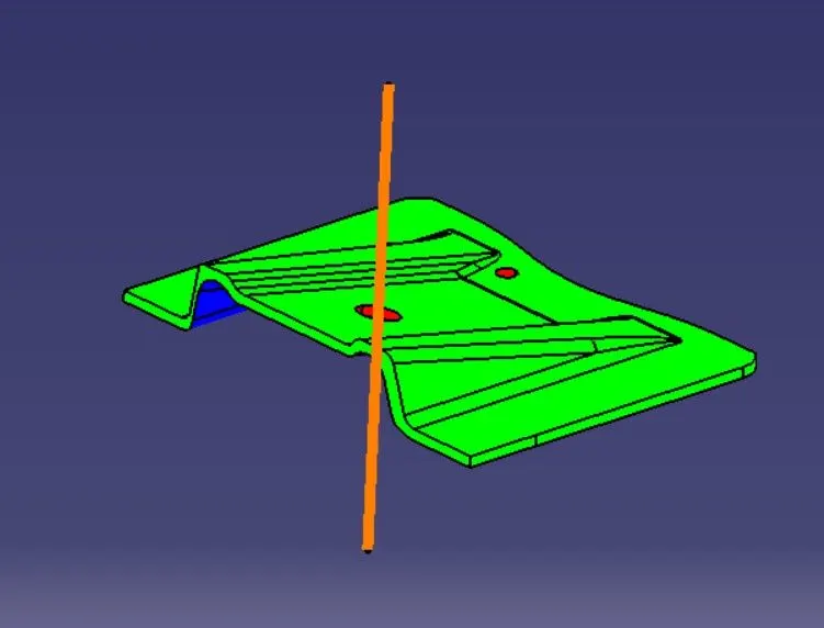
(The above image is shown for tooling axis alone)
CLASS B SURFACE:
The class B surface is created using the offset command of Class A, though it is created considering three main parts that is base surface , RIB1 RIB 2 and slope region. The holes shall be considered later.
It cant be offsetted directly as the fillet regions are there in Class A Surface, the radial surfaces are extracted and untrimmed and joined with perpendicular parts and the final radius is given based on the class A radius and offset distance.
Class C Surface :
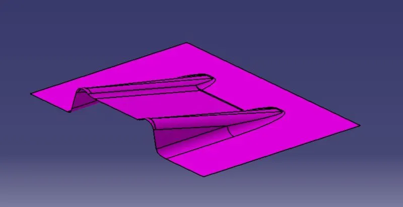
The class C surface is created using the boundary of class A, in which due to connexity constraints , the boundaries are split into two . the split boundaries are swept perpendicular to B surface passing it. as we need to create the closed surface. The c surface is created considering the draft direction ie tooling axis in swept operation.
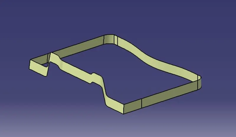
Final Trims of Surface:
The holes are created in c -surface considering the draft direction and the angle and swept and trimmed with B surface.
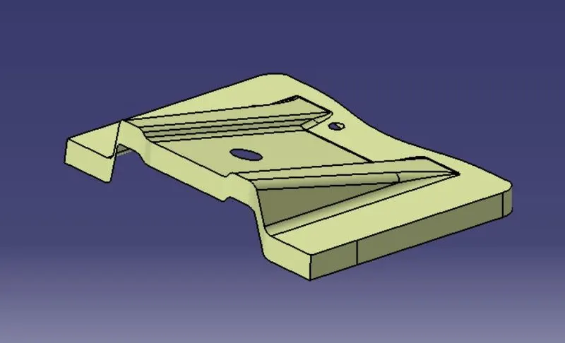
The C surface is joined with the class A surface before trimming it with B surface.
Once joined the joined surface is trimmed with B surface , inorder to create the final product.
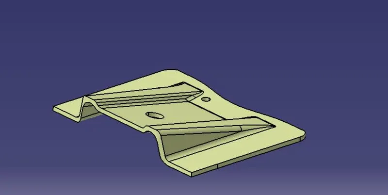
Once completed the surface part is checked for any boundaries, and if its okay its been converted into part body using close surface command,
Draft analysis is performed in the final part and the corresponding results are as follows,
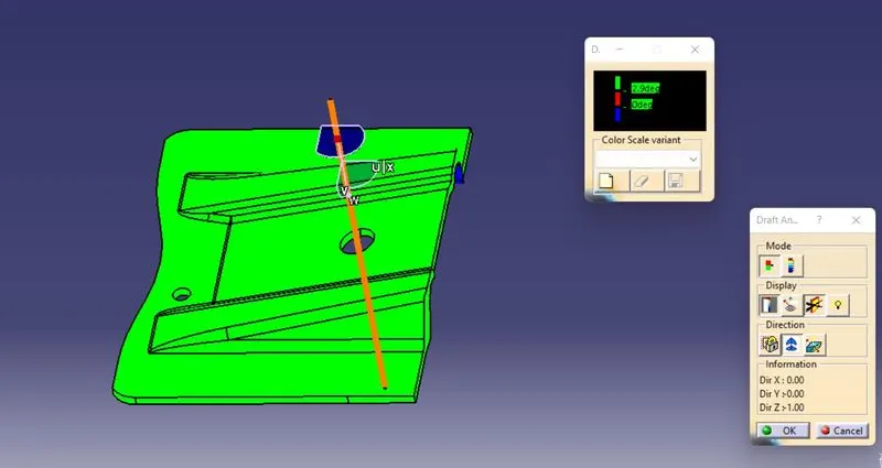
all parts can be ejected from tool easily based on draft analysis.
Tree structure and geometrical sets:
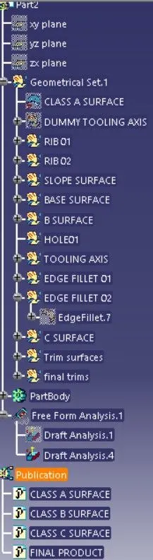
Proper tree structure is maintained for ease of acess and the neccessary surfaces has also been published.