Design of backdoor
BACK DOOR
AIM:
Design of the car back door.
OBJECTIVE:
1. From the given styling surface, develop a back using appropriate design methodologies.
2. Provide the neccessary reinforcements and emboss defenitions.
SOFTWARE USED:
CATIA V5
INTRODUCTION:
"Back Door" is a door or door system on the back end of a motor vehicle through which passengers can enter or depart the vehicle or cargo can be loaded or unloaded. It does not include:
(a) A trunk lid; or
(b) A door or window that is composed entirely of glazing material and whose latches and/or hinge systems are attached directly to the glazing material.
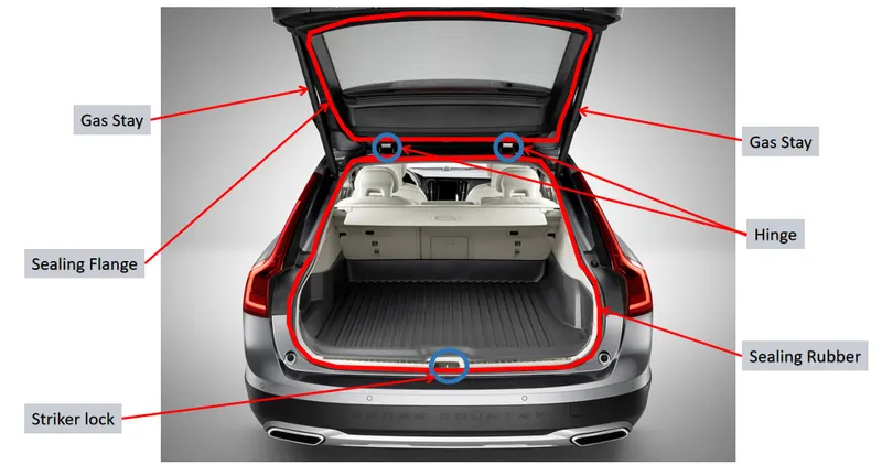
In most of the cars, these back doors are operated with help of gas stay which in turn reduces the effort required to lift the door. Some luxury cars have a powered backdoor which in turn is driven by an electric motor. This kind of system is also hatch back or station wagons are sold as 3 doors or 5 doors models. In this case, the rear hatch is classified as door this is because it enters the passenger compartment. The naming is mainly usedin european countries. In the case of safety, backdoor designed should meet the safety requirement of rear collision.
The door or opening of cargo area may be hinged at the top, side and bottom. If the door hinged in the bottom it is called a tailgate.
1.Top Mounted
2.Side-Mounted doors
3.Bottom type
"Latch" is a device employed to maintain the door in a closed position relative to the vehicle body with provisions for deliberate release (or operation).
“Hinge” is a device used to position the door relative to the body structure and control the path of the door swing for passenger ingress and egress.
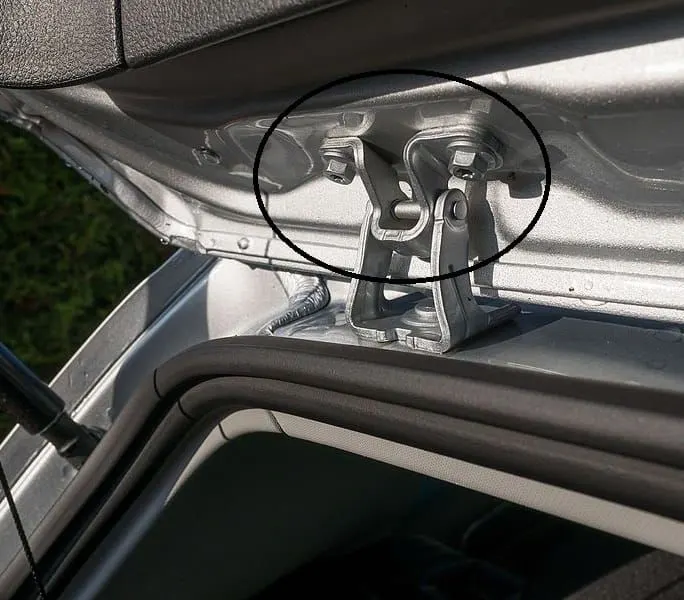
"Gas Stay" type backdoor is an ideal and most commonly used tailgate mechanism from lower segment car to luxury car segment. The ideal components of the tailgate consist of a hinge, door, gas stay, and some rubber beadings for sealing of the door.
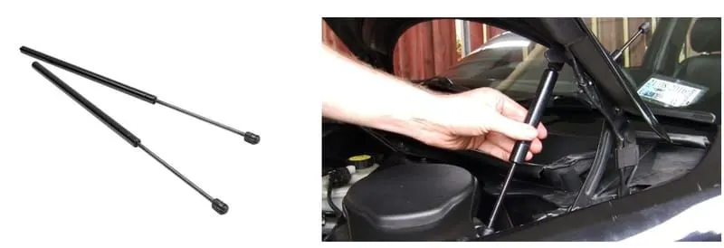
PROCEDURE
1.checking the Geomtry:
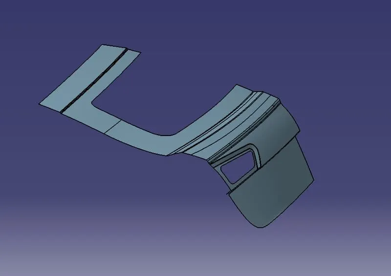
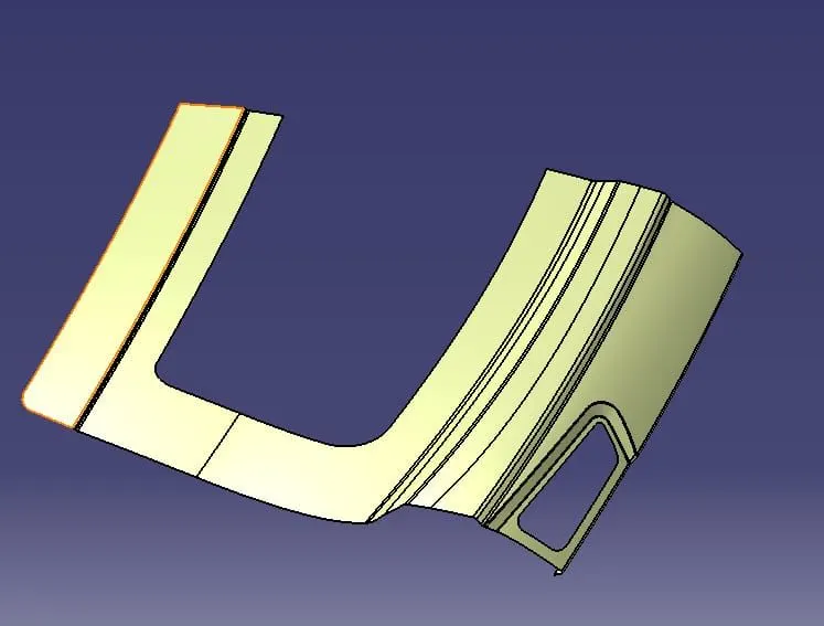
- The above class A styling surface is an input for designing the backdoor panel.
- The styling surface for the upper panel needs to be checked to have the proper connectivity with no gaps between them. As seen here the surfaces are not connected.
- To create the upper panel we use the trim, extrapolate, andd blendtools to join the styling surfaces.
- Especially the tail lamp area is the surfaces were first extrapolated trimmed and then given the fillets.
2.Creating The Tooling Axis:
- Click on the line option and select the Bisecting option.
- Now, Right Click on the 1stLine option to create a line. Select the point from the Vertex of the Upperside of the corner to the position where the declination starts. Click ok and the line is created.
- Now, click on the Second Line and follow the same procedure but from the lower surface. Click Ok and the line is created.
- After clicking ok, the bisecting line is created.
- You can also use a Point and direction method to create a tooling axis.
- The line created is the main tooling Axis.
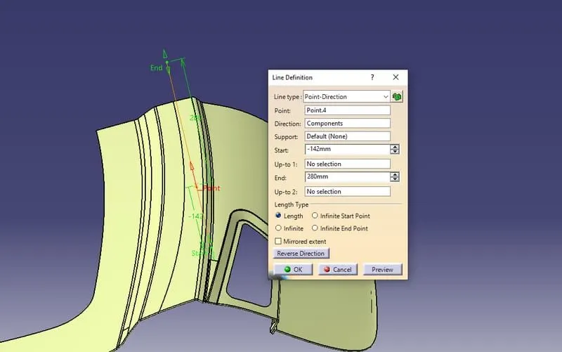
3.Creating The Outer Panel Upper Surface:
- To create the upper panel, the areas that are created before need to be joined together. Once those are joined the hemming needs to be done.
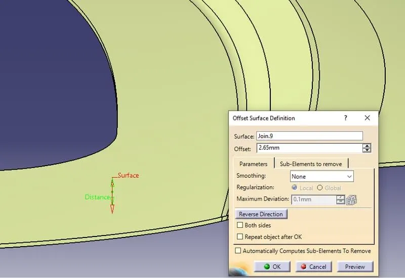
- To perform Hemming, offset the present surface to 2.56mm( Outer Surface Thickness-0.75gap between outer and Inner panel-0.2mm, Hemming area bent region -0.75mm, the gap between hem and inner panel -0.2mm).
- Use the parallel curve option to 10mm to create the surface.
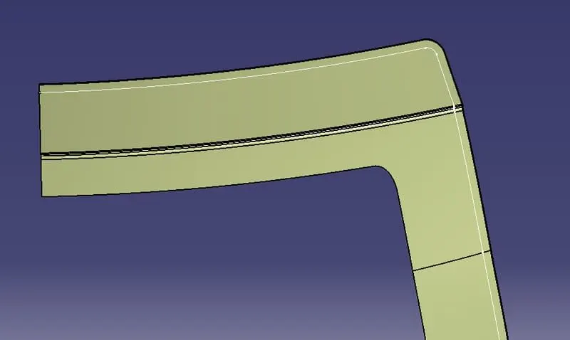
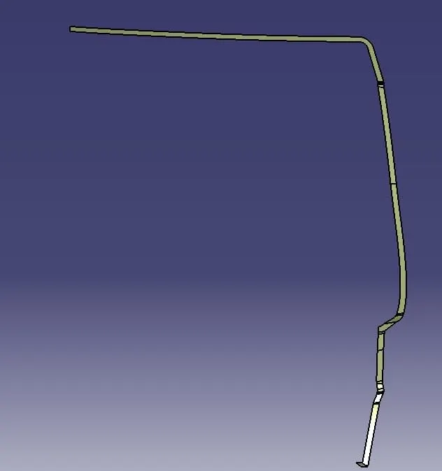
- Use the connect option to create the curved line. We can use the spline option as well.
- Select the point and the support lines with a tangency of 2.
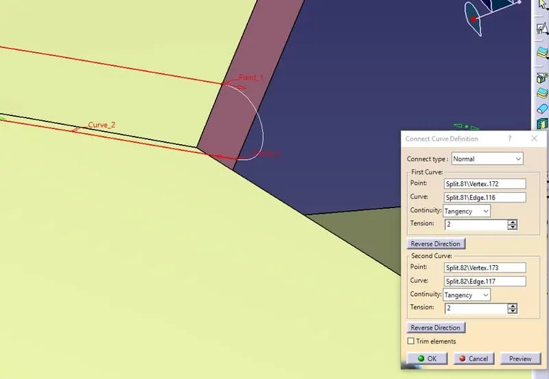
- use the multi-section surface option to fill the surface and join the surfaces.
- Near the corner , areas create the sketch to perform a acut-out of those sections.
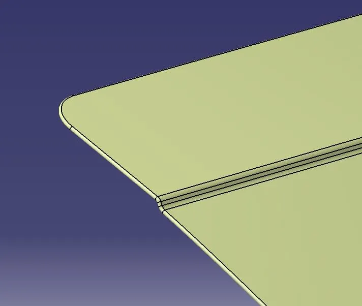
4.Creating The Outer Panel Lower Surface:
- To create the lower panel, extration of the lower end of the upper part need to be done.
- Offset it to 0.2mm and extrapolate the lower panel and the 2 surfaces.
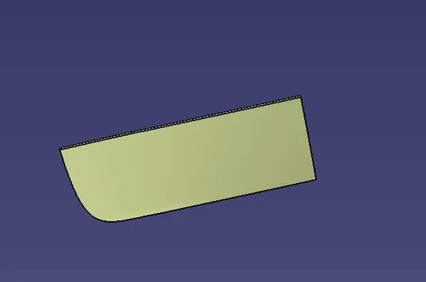
- Now give an edge fillet of 3.5mm.Offset the created surface to 2.65 to perform hemming.
- To perform Hemming, offset the present surface to 2.65mm (Outer Surface Thickness- 0.75mm, Inner panel thickness- 0.75 gap between Outer and Inner panel – 0.2mm, Hemming area bent region- 0.75mm, the gap between hem and Inner panel- 0.2mm)
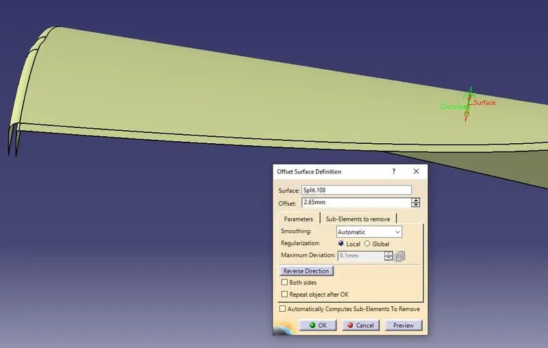
- Use the parallel curve option to 10mm to create the surface.
- Use the connect option to create the curved line. We can use the spline option as well.
- Select the points and the support lines with a tangency of 2.
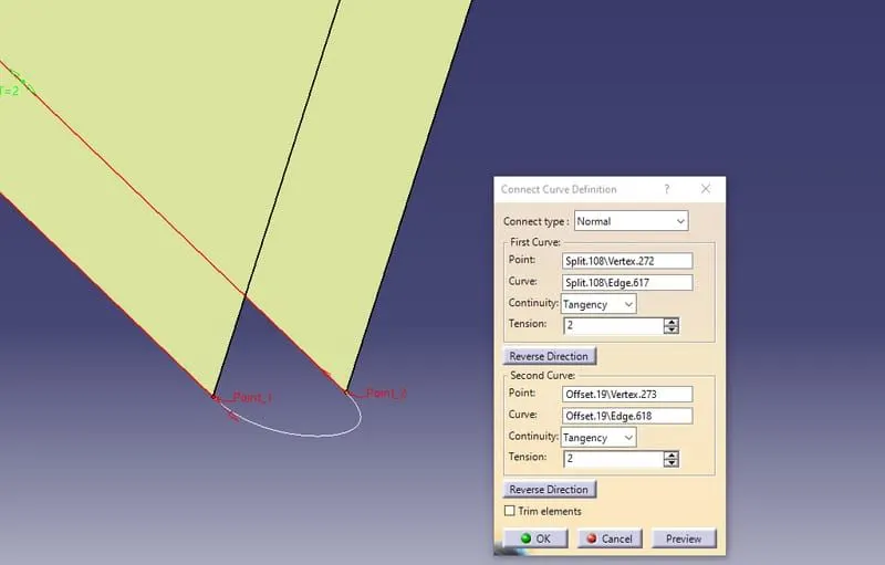
- Use the sweep option to fill the surfaces with help of two guide curves and join the surfaces.
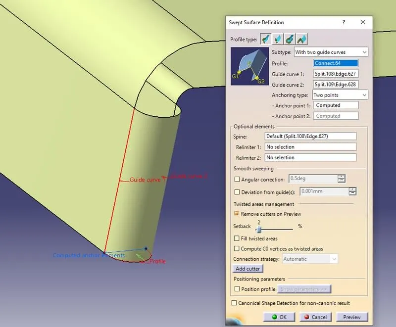
- Near the corner, areas create the sketch to perform a cut - out of those sections.
5.Creating The Inner Surface:
- To create the inner surface, first select the upper and lower surface and join them together with the fillet of the 3mm.
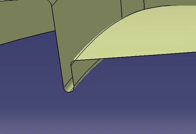
- Now, create the offset of 1.7mm and again offset it 25mm downward.
- Use the parallel curve option to cut the elements.
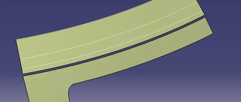
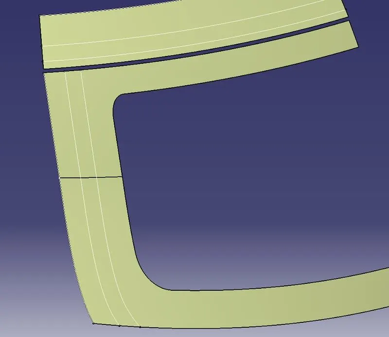
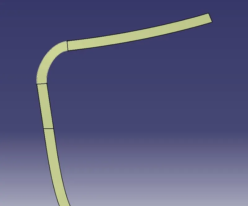
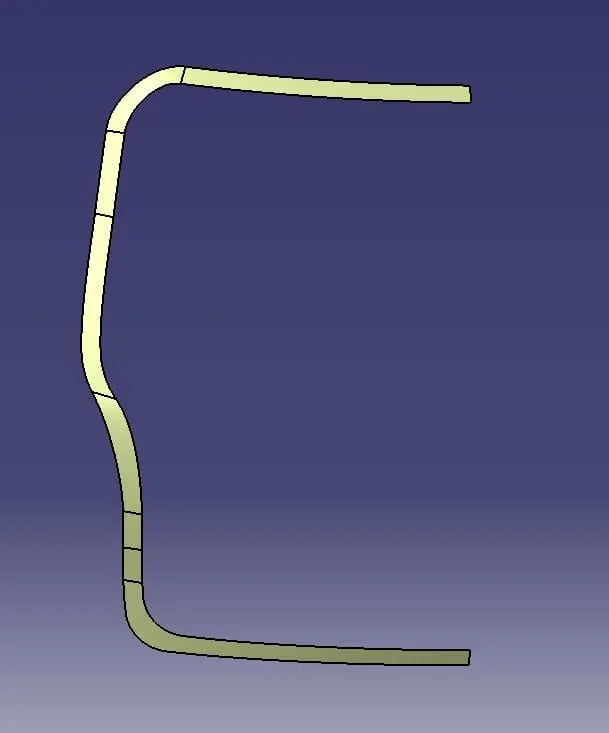
- Use the Sweep option to create a sweep with an angle of 25 degrees with the tooling axis.
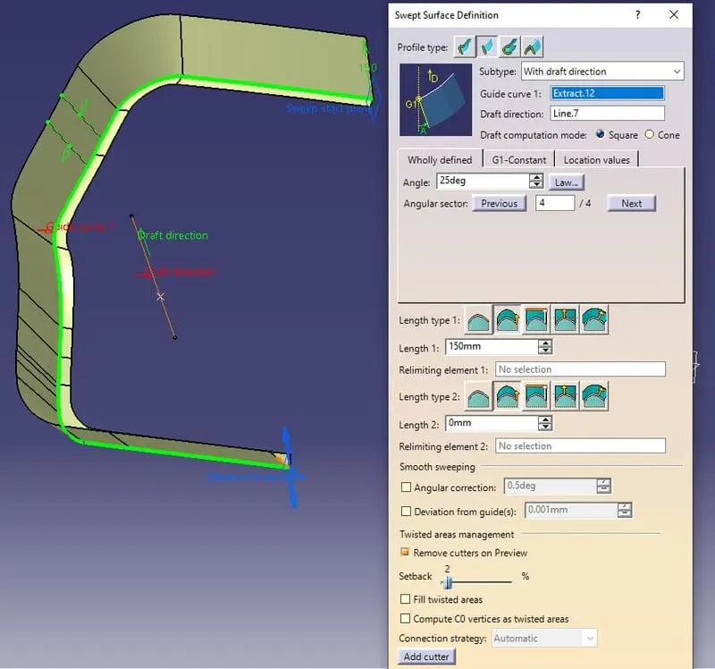
- Now, use the offset of 1.7 to trim the sweep and creating a surface.
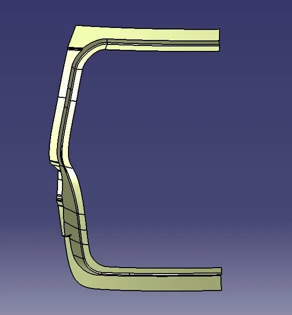
- After creating the boundary surface of the inner surface, extract windshield area and extract it.
- Now create a sweep inside with an angle of 25 degrees and trim it with windshield extract.
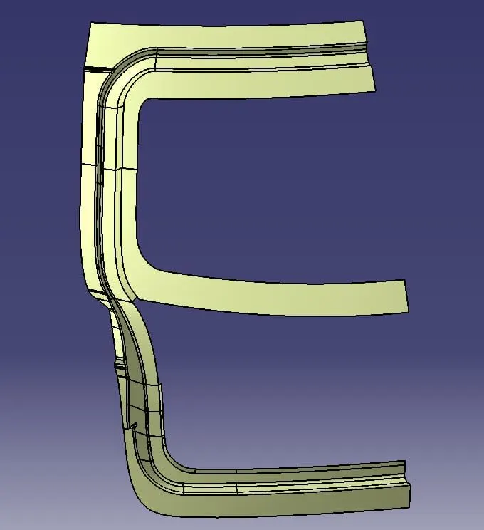
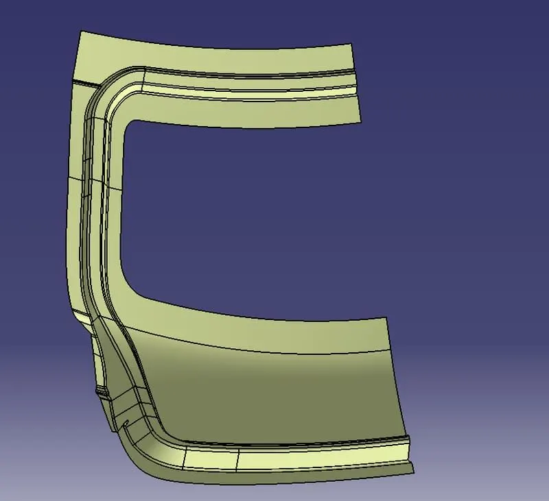
- Similarly, create the lower side surfaces using the connect option and trim.
- Give the fillet value of 5mm to the corner surfaces.
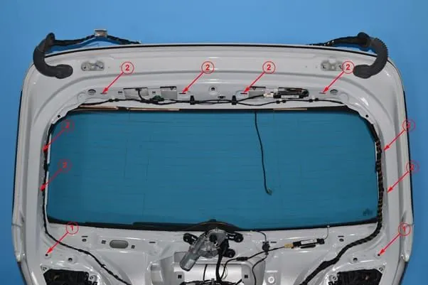
6.Making Hinges And Gas stays on the Inner Surface:
- The hinges are created at the top of the inner panel using the parallel curves and corner option.
- Use the split option to cut the elements and perform a sweep with an angle of 10 degrees.
- Offset the surface to 4mm and trim it with the sweep surface. Give the fillets of 4mm to it.
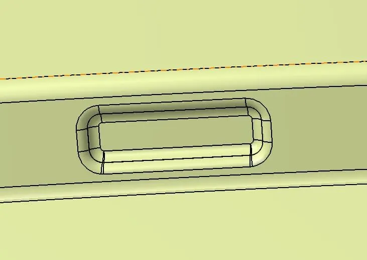
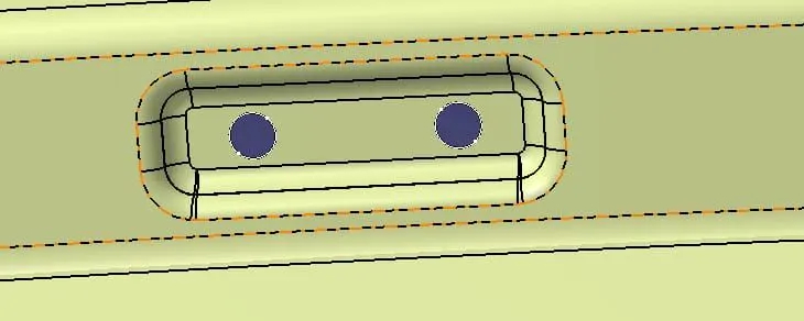
- The gas stays part is created at the side of the inner panel. Follow the same process as the hinge part to create the gas stay embossment.
7.Creating the Reinforcements:
- To create the reinforcements, select the surfaces with the nearby areas and extract them. Use the line option to create the line on the surface.
- Split the surface and select the surface and offset it to 0.75mm.
- Follow the same procedure for the gas stay and latch parts as well.
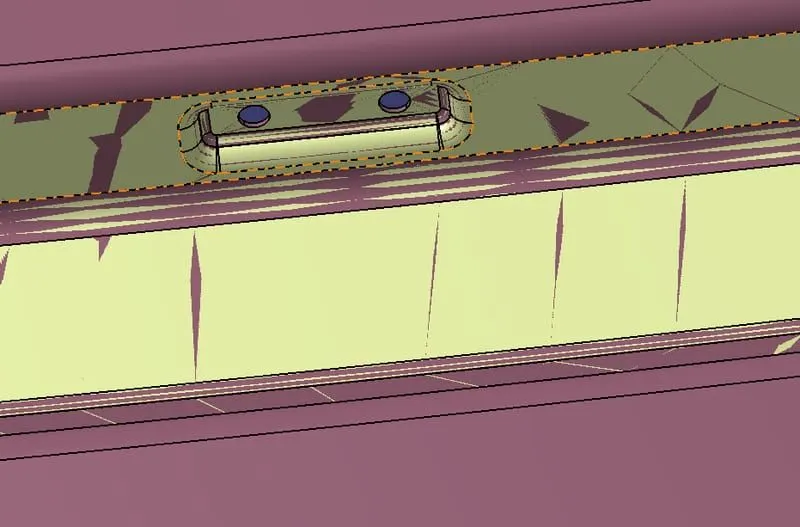
8.Generating a solid:
- Go to the Part design, Create a New Part Body for the Upper part, Lower part, Inner panel, and reinforcements (each for Hinges, Latch, and Gas stay).
- Use the Thick surface option to create the solid with thick of 0.75mm for back door parts and 1mm for reinforcements.
RESULT:
The back door of a car is created along with the necessary reinforcements that help to improve the strenth and stability of the back door.
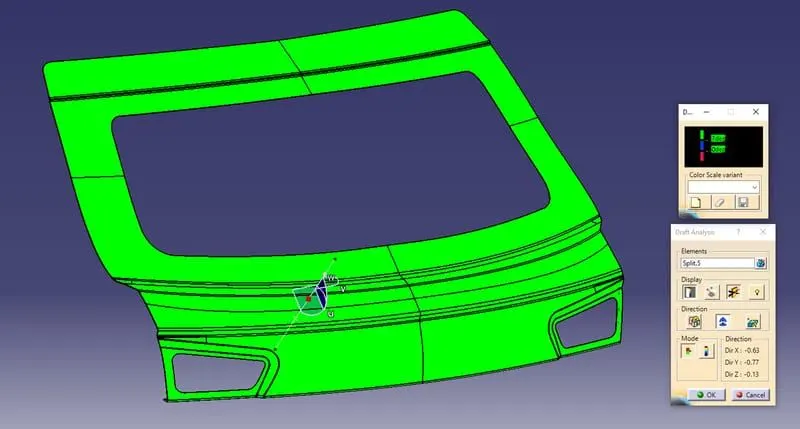
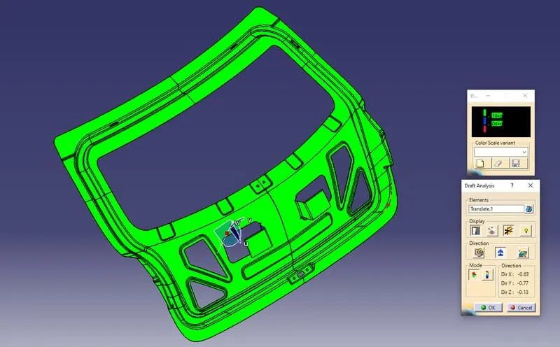
DRAFT ANALYSIS: