Fender Design
FENDER DESIGN
INTORDUCTION
Fender is a BIW component used as a frame for the wheel, th main purpose od afender in an automobile is to protect the engine compartment from sand, dust, small stones, etc which are thrwon into the air by the tire grip. These can cause damage to the car body and hence we use a fender to guard the tire. We havefront as well a arear fender in acar, the rear fender is integrated with the body side. The fender is a seperate closure commodity.
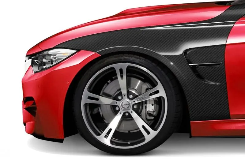
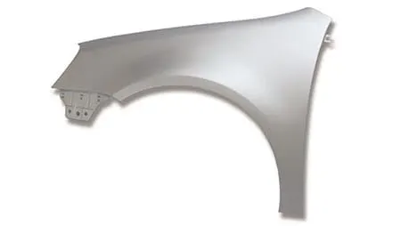
There are two types of the fender in general:
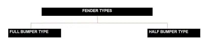
- Full bumper type
- Half bumper type
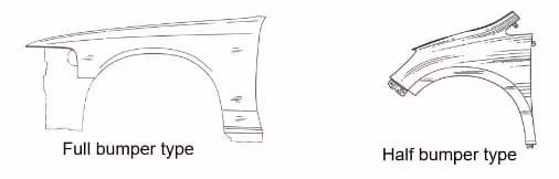
- Presently we are using the half bumper type, the reason for choosing the half bumper type the blank used for creating it is very large and also has a lot of wastage, but in the case of the half bumper type we have the possibilty to reduce the scrap.This is what we called as scrap management.
- In half bumper type we reduce the usage of the steel material and uses the lots of plastic on the bumper which inter decreases the cars weight and increase the performance.
FENDER WHEEL ARCH
- Fender wheel arch is having some standard specification, for example if you see the car from the front, if yo see the wheel outside the front. if you see the whole outside fender it does more chipping and it causes lots of damages to the pedestrians and aslo to the car.
- In order to maintain the pedestrians safet we have to position the tire wheel inside the fender.
- for the European requiremnet the clearance between the wheel and fender outer most skin is mm.
- This requireents changes from country to country based upon the road conditions.
ASSEMBLY
There are two types if assembly they are
- Bottom up assembly
- Top down assembly
Bottom up assembly: The bottom-up assebly is the most preferred approach for creating assembly models. In this type of the assembly the components are cratedd in part design work bench files. Parts are conconceived in assembly design work bench using product structure tools. After inseting each components, constraints are applied to positon them properly in the D space with respect to the other components. This assembly is preffered for large assemblies, especially those having inticate individual components.
Top-down assembly:In the top assembly design approach, componnets are created inside the assembly design workbench. Therefore, there is no need to create seperate part files of the components. This design approach is completely different from the bottom-up design approach. Here you have to create the product file first and then one by one create all the components. Note that even then the parts are created the product file, they are saved and opened idnividually one by one when they are needed. Here the construction and the assembly takes place simultaneously.
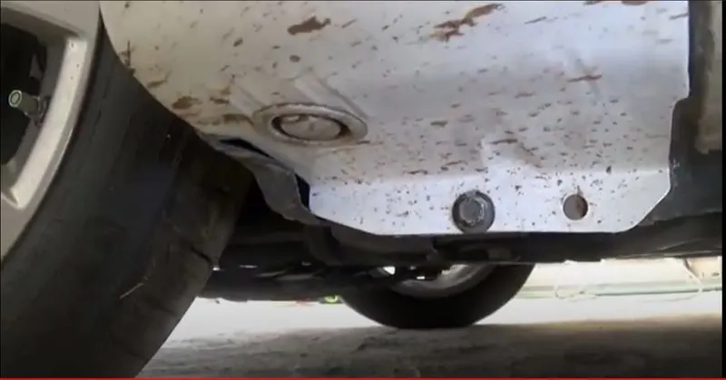
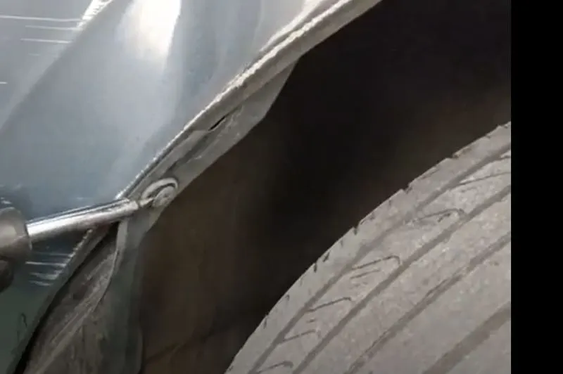
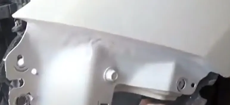
Mounting Regions On Fender
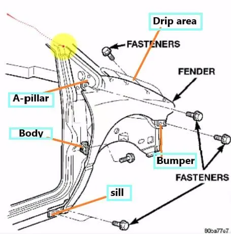
- Still Mounting
- Splash Cover Mounting
- Bumper Mounting
- Drip Area
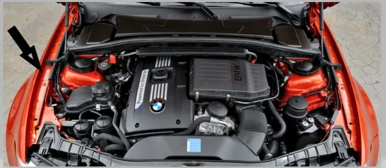
- A-PIllar Mounting
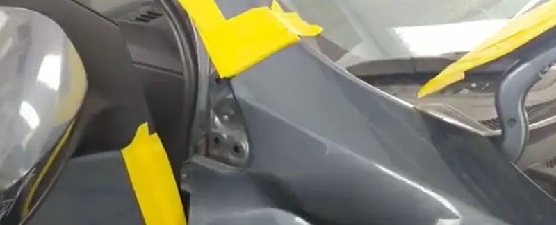
DESIGN
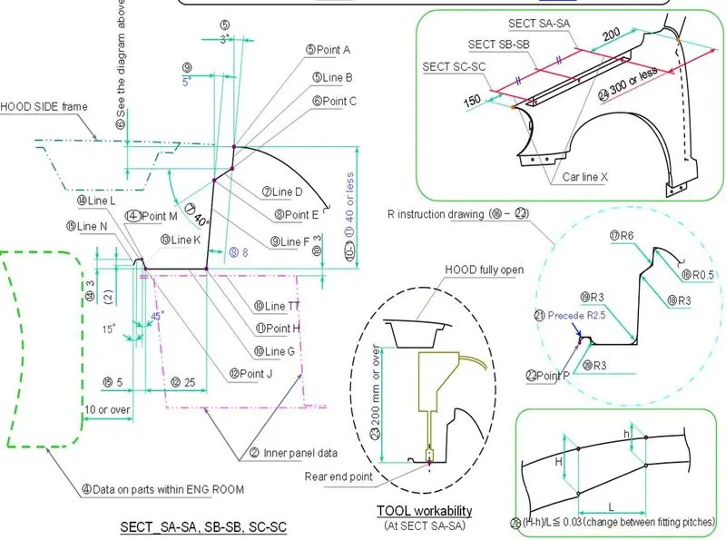
Given Data:
DESIGN PROCEDURE
Drip Area: It is the most important mounting unit of a fender. It is connected with the engine compartment and therefore a lot of design constraints are to be followed while designing the drip area.It should have sufficiwnt clearance from to accommodate the cowl mounting region and the Headlamp housing unit respectively.The master sketch provides the linear and angular measurement for designing the drip mount after talking into considerations various factors like Hood Opening, Tool workability, Aesthetics, Spring Back effect due to exceed lenght etc.
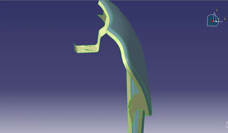
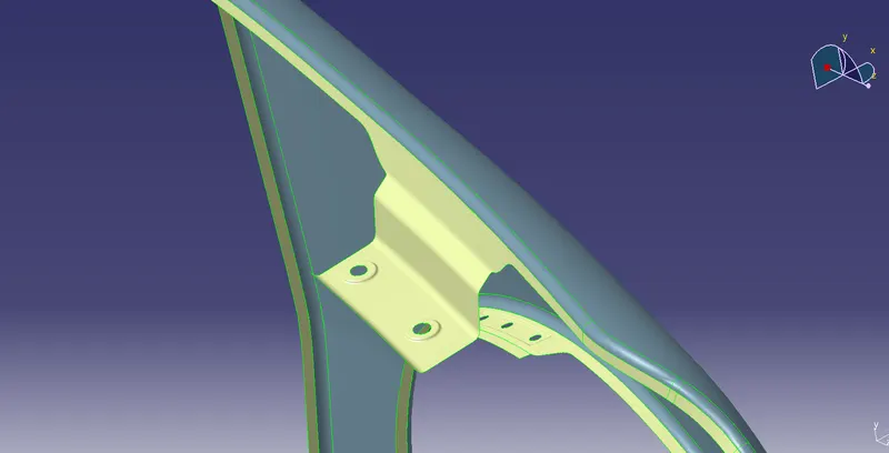
Fig.Side View Fig. Top View
Other Mountings
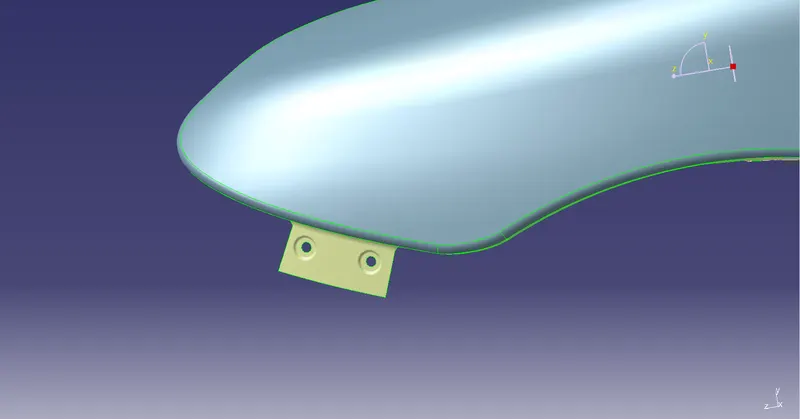
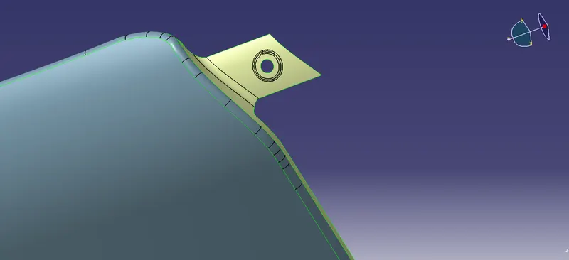
The mountings for Bumper, A-Pillar Flush and still area were designed according to engineering standards by providing adequate relief producibilty.
Bumper Mount Region:
A-Pillar Mount Region:
Flush Mount Region:
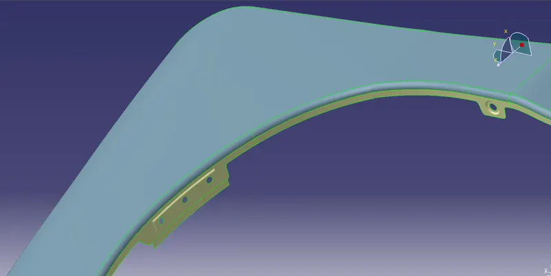
Sill Mount Region:
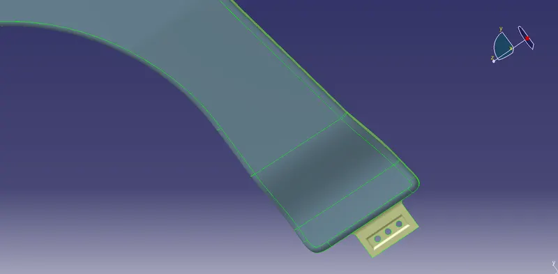
Embossing was provided on the mounting to strenthen them during fastening.
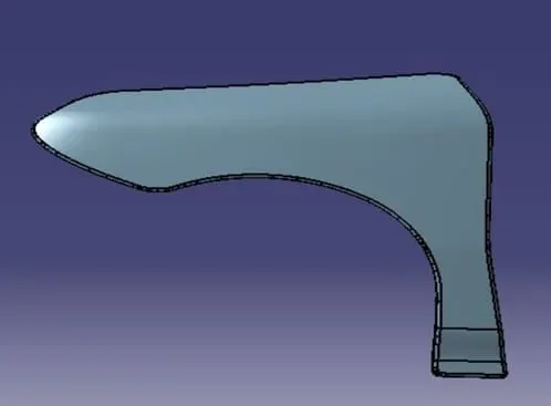
Commands under GENERATIVE SHAPE DESIGN workbench of CATIA V5 were used extensively for various operations along with Part Design workbench commands. Industry standard Fillets, reliefs and design constraints were applied to ensure productibility.
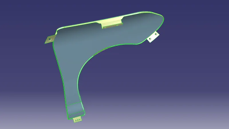
Fender with all Mounting
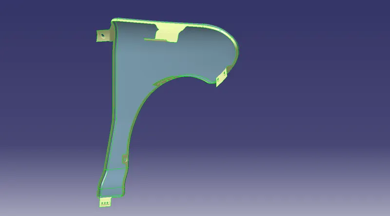
Fender Front View:
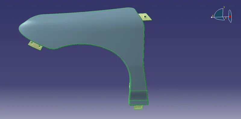
Fender Rear View:
CONCLUSION
Thus the Drip Area, Bumper mount region, A-pillar mount region, Sill mount area were designed for the Fender from the given Master section and inputs with the help of Catia V5.