Section Modulus calculation and optimization
AIM
Use the section from the Hood Design and calculate the Section Modulus, come up with a ne section that has improved the section modulus of the previous section and mention what change you made that has increased the strenght.
SECTION MODULUS
Section modulus is a geometric property for a given cross section used in the design of beams or flexural members. Other geometric properties used in design include area for the tension and shear, radius of gyration for the compression, and moment of inertia and polar moment of inertia for stiffness.
There are two types of section moduli, the elastic section modulus and the plastic section modulus.It is termed as the ratio of second moment of area and distance from N>A ( Neutral Axis )to the extreme fiber. Also it is the measure of streth of given member. The stress in outermost section of beam is computed with the help of section modulus. It is indicated by S.
Section modulus is indicated as follows:
S = I/y
Where,
S = Section Modulus
I = Moment of Inertia
y = distance between the neutral axis and the extreme end of the object
Unit of section modulus is in (mm^3 ).
Section modulus depends only on the cross section shape of the beam. Cross section shape of the beam. Cross section shape like rectangualr, square, circular, I section and T, composite section etc.
For symmnetric sections, the value of section modulus is both above and below of centroid of the fiber. Due to different distance from mdistance from centroid to the top and bottom of the material, the maximum section modulus is S max and the minimum section modulus is S min.
Section modulus is also expressed as the ratio of bending moment to the bending stress of a given object with elastic limit.
SIGNIFICANCE OF SECTION MODULUS
The Section modulus of the cross section al shape is of significant importance in designing beams. It is a direct measure of the strenth of the beam. A beam that has a larger section modulus than another will be stronger and capapble of suporting greater loads.
- Section Modulus is the important factor for design of beam and flexural member.
- Higher the value of section modulus, higher will be the resistance of member to bendng.
- It is required to calculate stresses in beams.
- It is required to calculate stresses in beams.
- It is used to calculate strenth of the steel structure.
- More the section modulus, it can withstand more load and it is also considered to be more tougher.
IMPORTANCE OF SECTION MODULUS:
- It is significant for beam and fluxural member design.
- More the section modulus, more the member is ressistant to bending of the beam.
- It is easier to calculate streses in beam and an exact measure of strenth of steel.
- if two beams are made of same material and comparing the Section Modulus of two beams, the beam with bigger section modulus will be tougher and more capable to withstand larger loads.
PROCEDURE
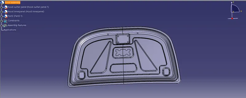
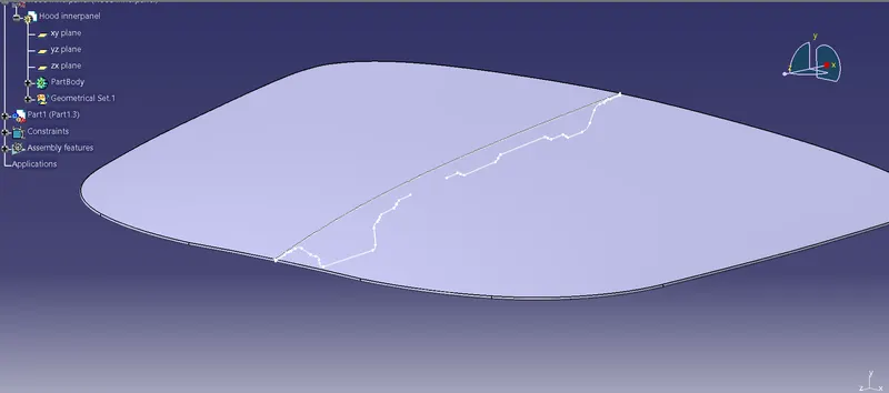
Taking out the intersection of the inner panel and outer of the model shown below:
CASE 1
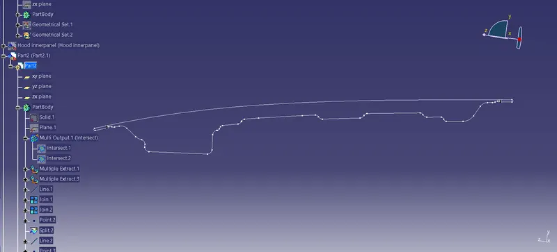
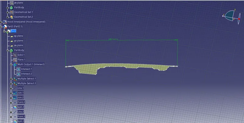
The above shown Fig. refers the 2D sketch of th Hood intersection part. By this we can calculate the hood section modulus.
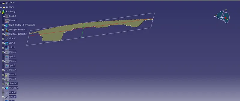
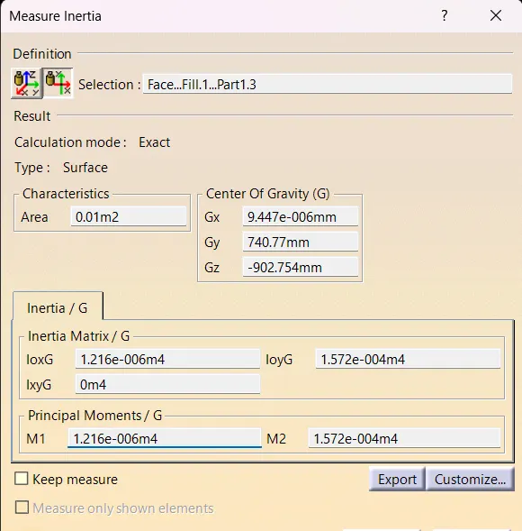
IN NX or CATIA V5 software we have a command called Section Inertia, by this we can automatially get the Moment of Inertia values.
----------------------------------------------------------------------------------------------------------------------------------------------------------------------------------------------------------------------------
Component | Sub-Component | Area[m2] | Gx[mm] | Gy[mm] | Gz[mm] | M1[m4] | M2[m4] | IoxG[m4] | IoyG[m4] | IxyG[m4] |
----------------------------------------------------------------------------------------------------------------------------------------------------------------------------------------------------------------------------Face...Fill.1...Part2.1 | | 0.010 | 9.44686e-06 | 740.770 | -902.754 | 1.21645e-06 | 0.000157174 | 1.216e-006 | 1.572e-004 | -1.626e-019 |
----------------------------------------------------------------------------------------------------------------------------------------------------------------------------------------------------------------------------
The above mentioned is the Moment Of Inertia ( Max. and Min. ) values of Hood part.
MOI(max) : 1.572e-004 *10^5 (mm^4)
MOI(min) : 1.216e-006 *10^5 (mm^4)
The Fig. below refers to the distance between hood from one end to extreme end.
The total distance of the hood
Y=487.411
CALCULATION
Let, the moment of inertia ( max & min ) values of Hood part be
MOI(max) : 1.572e-004 *10^5 (mm^4)
MOI(min) : 1.216e-006 *10^5 (mm^4)
The total distance of the hood Y=487.411mm
Distance between the nuetral axis to the extreme end= (487.411/2)=243.7mm
For asymmetric has two values for the top and bottom of the centroid that is Smax and Smin.
Section modulus is the ration of second moment of area and the distance from the nuetral axis(NA) to the extreme end, it is given by
S = I/y
therefore,
Smax= I(max)/Y = (1.572*10^5)/(243.7) = 645.055mm^3
Smin= I(min)/Y = (1.216*10^5)/(243.7) = 499mm^3
CASE 2
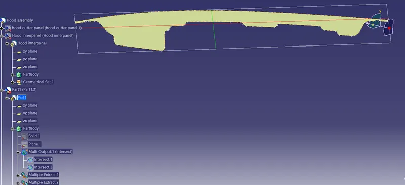
In this case 2 we are offsetting the hood inner panel about 0.5mm downwards. Why because Higher the value of section modulus, higher will be the resistance of member to bending so thats why the hood inner section is increased.
Below Fig. refers that 2D sketch of the inner panel is offset by 0.5 mm downwards as shown.
----------------------------------------------------------------------------------------------------------------------------------------------------------------------------------------------------------------------------
Component | Sub-Component | Area[m2] | Gx[mm] | Gy[mm] | Gz[mm] | M1[m4] | M2[m4] | IoxG[m4] | IoyG[m4] | IxyG[m4] |
----------------------------------------------------------------------------------------------------------------------------------------------------------------------------------------------------------------------------
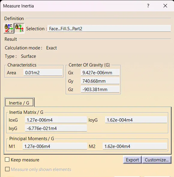
Face...Fill.5...Part2.1 | | 0.010 | 9.42721e-06 | 740.668 | -903.381 | 1.2697e-06 | 0.000161974 | 1.27e-006 | 1.62e-004 | -2.507e-019 |
----------------------------------------------------------------------------------------------------------------------------------------------------------------------------------------------------------------------------
After offsetting the inner panel about 0.5 mm then got MOI of this particular section
MOI(max) : (1.62e-004*10^05)mm^4
MOI(min) : (1.27e-006*10^05)mm^4
The total distance of the hood Y = 487.411mm
Distance between the nuetral axis to the extreme end= (487.411/2)=243.7mm
S = I/y
therefore,
Smax= I(max)/Y = (1.62*10^5)/(243.7) = 664.75 mm^3
Smin= I(min)/Y = (1.27*10^5)/(243.7) = 521.13 mm^3
Comparing CASE 1 and CASE 2
CASE 1
S(min) = 499mm^3
CASE 2
S(min) = 521.13 mm^3
Increasing the gap between the outer and the inner panel leads to the increament in the section modulus, so the resistant to bending will also be get increased due to this strength of the hood will increase.
Now the change % will come as ,
S=[(664.75 mm^3)-(521.13 mm^3)/(521.13 mm^3)]*100=27.55%(inc.)in the section modulus.
CONCLUSION
The section Modulus in the second case is higher than the first one. Similarly the Yield Moment also increases proportionately, thereby corresponding to greater strenth of the Hood. This was achieved due to an increased area by adjusting the position of the outer hood, without altering any standard safetly design constraints.