Design of backdoor
Aim: To design the back door assembly from the given Class-A surface.
Back Door: The trunk (North American English) or boot (British English) of a car is the vehicle's main storage or cargo compartment, often a hatch at the rear of the vehicle. It is also called a tailgate.
In Indian English the storage area is known as a dickey and in South-East Asia as a compartment.
The trunk or luggage compartment is most often at the rear of the vehicle. Early designs had an exterior rack on the rear of the vehicle to attach luggage trunk. Later designs integrated the storage area into the vehicle's body, and eventually became more streamlined. The main storage compartment is normally provided at the end of the vehicle opposite to which the engine is located.
Some mid-engine or electric cars have luggage compartments both in the front and in the rear. Examples include the Volkswagen Type 3, Porsche 914, Porsche Boxster, and Toyota MR2. The mid-engine Fiat X1/9 also has two storage compartments, although the rear one is small, easily accessible, and practically cuboid in shape.
Rear-engine cars like Volkswagen Beetle or Porsche 911 have the trunk in front of the passenger compartment.
Sometimes during the design life of the vehicle the lid may be restyled to increase the size or improve the practicality and usefulness of the trunk's shape. Examples of this include the Beetle redesign to the 1970s 'Super Beetle' and the pre-war and 1950s post war Citroën Traction Avant.
The door or opening of a cargo area may be hinged at the top, side, or bottom. If the door is hinged at the bottom it is called a tailgate, particularly in the United States. They are used on station wagons and pickup trucks, as well as on some sport utility vehicles (SUV). Traditional drop-down station wagon and pickup tailgates can also serve as a mount for a workbench.
Traditional U.S. station wagons included a roll down window retracting into the tailgate to load small items or to allow the tailgate to be opened down on its bottom mounted hinges. Because of the potential for carbon-monoxide fumes, the tailgate window on station wagons should be closed whenever the engine is running.
Two-way station wagon tailgates may be hinged at the side and the bottom so they can be opened sideways like a regular door, or drop downwards as load platform extenders. They are designed with special handle(s) for opening in the selected direction on special hinges after the window is lowered.
A three-way design that was also used by Ford allows for the tailgate to be opened like a door with the window up. General Motors developed a clam shell style "disappearing" design where the rear window rolls up into the roof and the tailgate slides down and beneath the load floor. If the door is hinged at the top it is termed a hatch, and is used on a hatchback. A bottom opening door is now common on SUVs.
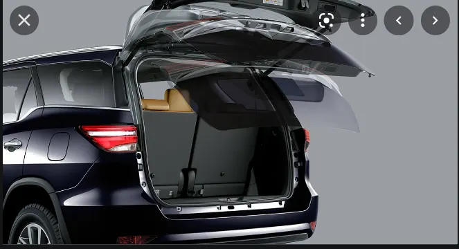
Fig. 1: Car back door.
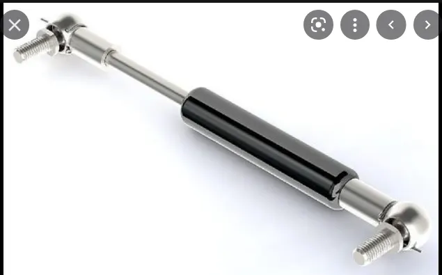
Fig. 2: Gas stay used in a back door of a car.
Design considerations for back door design:
- Functional requirement of hinge and gas stay.
- Rear visibility criteria.
- Crash analysis.
- Luggage volume.
- Gap and flushness requirement.
- Resistance to bending, torsion and endurance.
- Resistance to the denting test.
Components of Back Door Assembly:
- Outer panel upper half: The outer panel of the door assembly is the given Class-A surface for the project. It is the surface visible to the customer and hence needs to be smooth and styled appropriately. There are certain cut-out portions to fix the rear light assembly and handle to grab and open or close the back door.
- Outer panel lower half: The lower half of the back door covers the remaining part of the boot opening of the car. It is not mandatory to design the outer panel in multiple parts, but it is done to give the styling effect on the rear door.
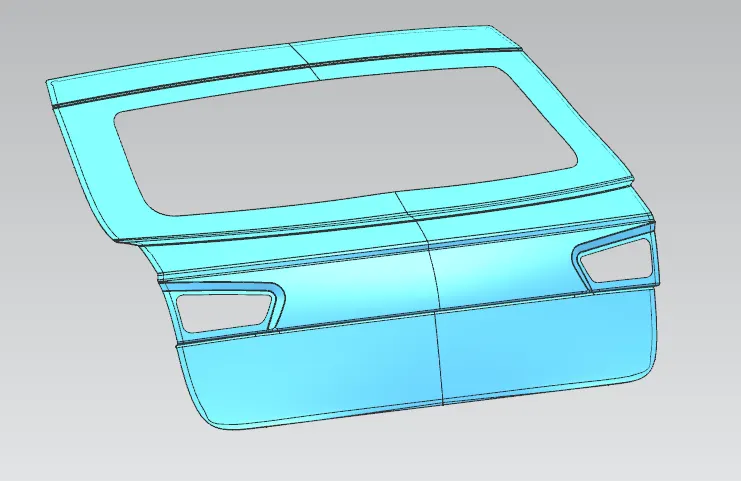
Fig. 3: Outer panel of the back door
- Inner panel: Inner panel is designed to accommodate all the necessary engineering features required for proper functioning of the back door, such as hinge mounts, gas stay mounts and latch mounts. These features should not be visible from the outside, hence they are designed on the inner panel. Inner panel also forms the support to the outer panel and gives strength to the back door assembly.
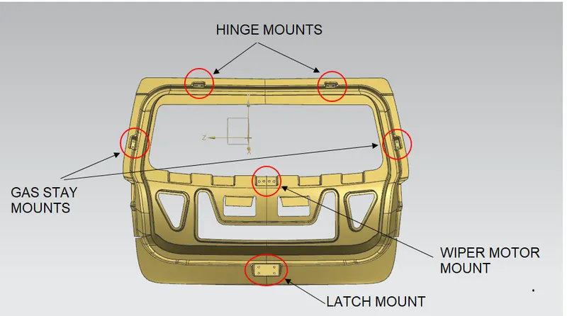
Fig. 4: Inner panel of Back Door Assembly.
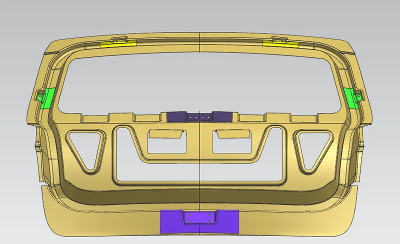
Fig. 5: Inner panel with reinforcements placed appropriately.
- Hinge reinforcements (LH & RH): The hinges are to be mounted on the inner panel as shown above. But the thickness of the inner panel is not sufficient to hold on to the forces acting on the hinge during the operation of door. Hence, to provide local strength, we use reinforcements as shown:
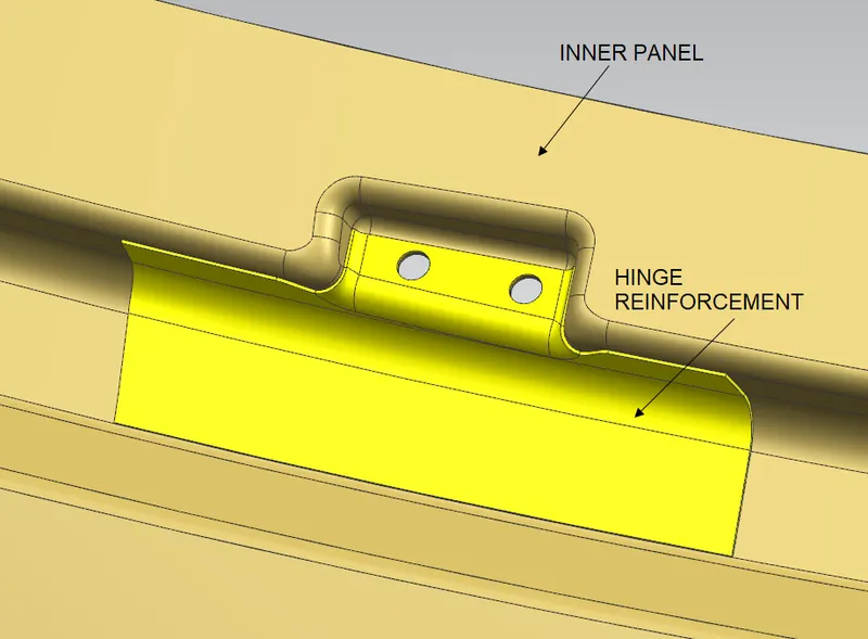
Fig. 6: Hinge reinforcements on the inner panel.
- Gas stay reinforcements (LH & RH): The gas stay are to be mounted on the inner panel as shown. But the thickness of the inner panel is not sufficient to hold on to the forces acting on the gas stay during the operation of door. Hence, to provide local strength, we use reinforcements as shown:
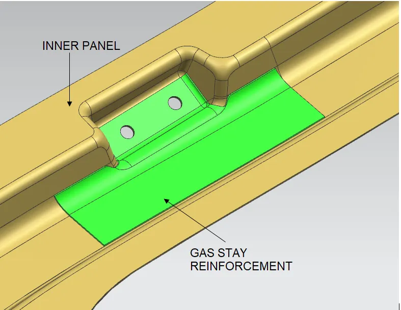
Fig. 7: Gas stay reinforcement on inner panel
- Wiper motor reinforcement: The wiper motor is to be mounted on the inner panel as shown. But the thickness of the inner panel is not sufficient to hold on to the forces acting on the wiper motor during the operation. Hence, to provide local strength, we use reinforcements as shown:
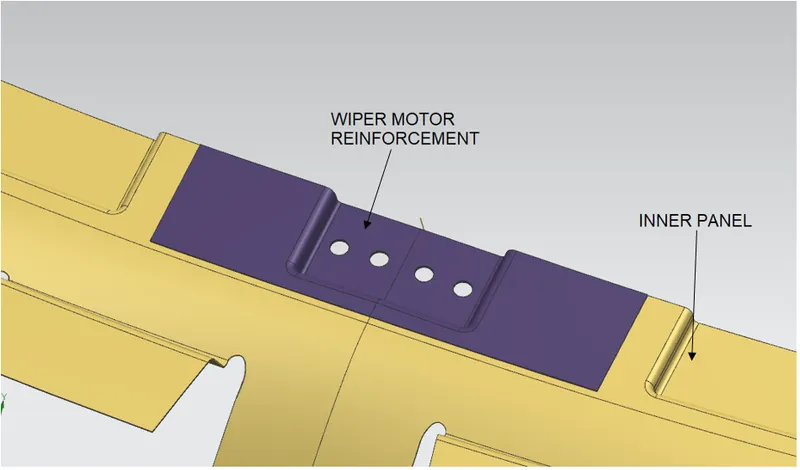
Fig. 8: Wiper motor reinforcement on the inner panel.
- Striker reinforcement: The striker is to be mounted on the inner panel as shown. But the thickness of the inner panel is not sufficient to hold on to the forces acting on the striker latch during the operation of door. Hence, to provide local strength, we use reinforcements as shown:
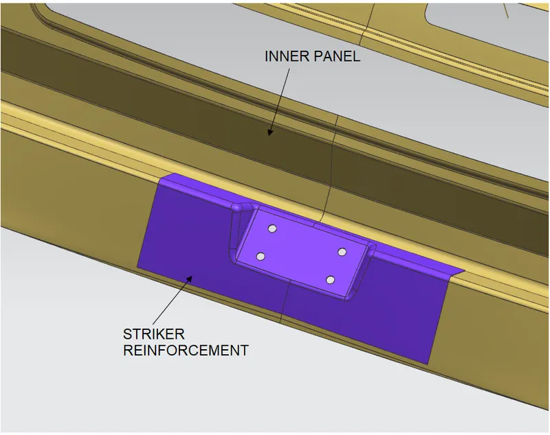
Fig. 9: Latch reinforcement on the inner panel.
There are numerous possible manufacturing process for the above parts, but when it comes down to the volume of the parts to be manufactured and the extent of the costs required to produce the parts on large scale, casting and sheet metal processing are generally employed.
In this case, the material used for manufacturing the back door assembly is steel, so we can use the sheet metal processing operations as mentioned below:
Sheet Metal Processing:
- Shearing: It uses a machine called power shear. Blanking and Punching are the shearing processes. When a closed profile is discarded, it is called punching, and when a closed profile would be used for further processing, it is called a blank and the process of cutting a blank from raw material is called blanking.
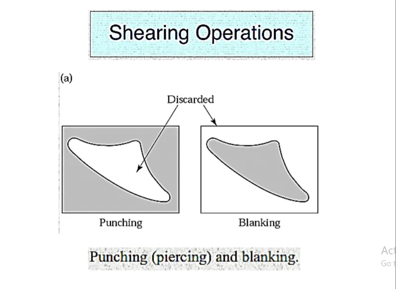
Fig. 10: Shearing operations on sheet metal.
- Bending: Sheet bending is defined as straining of the metal around a straight axis. During bending operation, the metal on the inner side of the neutral plane is compressed and the metal on the outer side of the neutral plane is stretched.
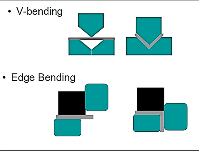
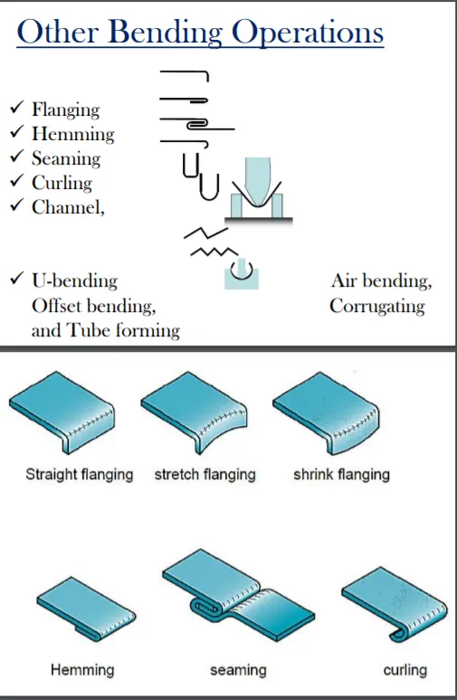
Fig. 11: Sheet metal bending operations
- Deep Drawing: Drawing is a metalworking process that uses tensile forces to stretch (elongate) metal, glass, or plastic. As the metal is drawn (pulled), it stretches to become thinner, to achieve a desired shape and thickness. The success of forming is in relation to two things, the flow and stretch of material. As a die forms a shape from a flat sheet of metal, there is a need for the material to move into the shape of the die. The flow of material is controlled through pressure applied to the blank and lubrication applied to the die or the blank. If the form moves too easily, wrinkles will occur in the part. To correct this, more pressure or less lubrication is applied to the blank to limit the flow of material and cause the material to stretch or set thin. If too much pressure is applied, the part will become too thin and break. Drawing metal requires finding the correct balance between wrinkles and breaking to achieve a successful part.
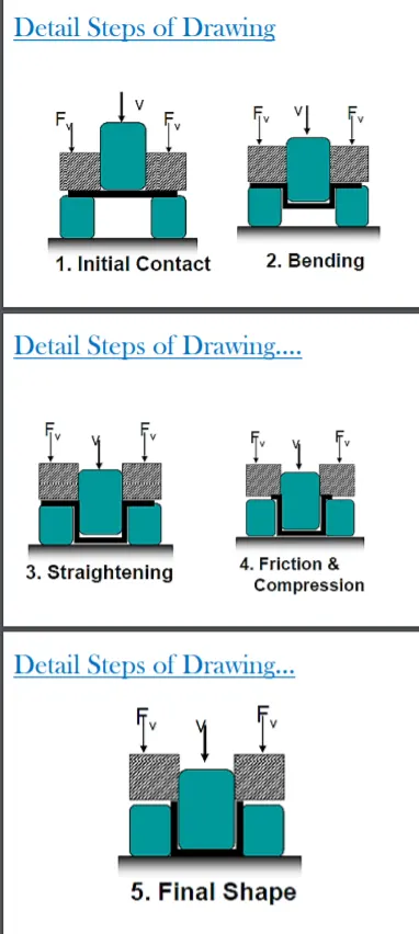
Fig. 12: Details of sheet metal drawing operation.
- Embossing: Sheet metal embossing is a stamping process for producing raised or sunken designs or relief in sheet metal. This process can be made by means of matched male and female roller dies, or by passing sheet or a strip of metal between rolls of the desired pattern.
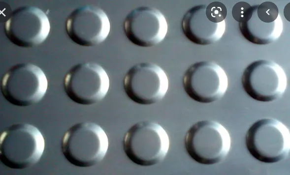
Fig. 13: Embossing a sheet metal
- Hemming: Hemming is a sheet metal forming process in which sheets are joined by bending it usually to 180°. Automotive body panels and automotive parts such as deck-lids, trunk-lids, doors, hoods and tailgates are formed by hemming process. Various grades of high strength sheets, aluminium alloys, recycle-friendly aluminium alloys, magnesium alloys, light weight alloys are used as work piece materials in hemming process. Classical hemming, roller hemming, robot assisted roller hemming, laser assisted roller hemming and hemming with electromagnetic forming processes are the experimental different approaches utilized for performing sheet metal hemming operations.
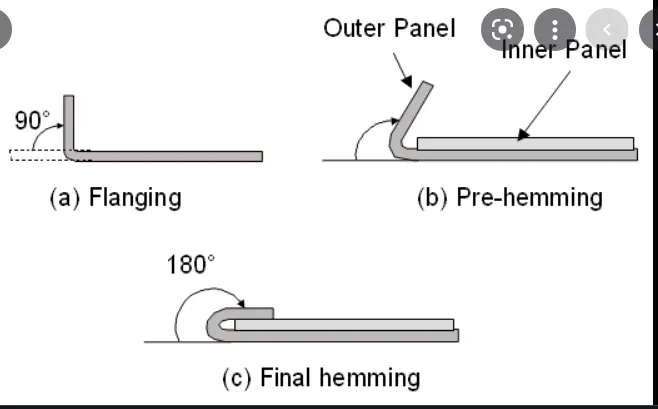
Fig. 14: Hemming of sheet metal.
Draft Analysis: The sheet metal processing operations require a minimum draft of 7 degrees w.r.t. tooling direction for manufacturing of parts without defects. The draft analysis of inner panel is shown below:
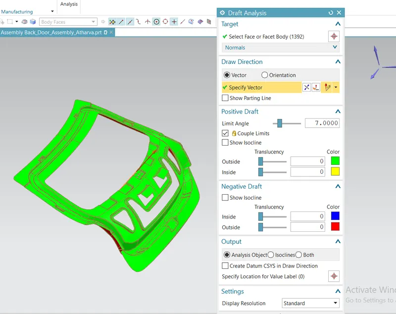
Fig. 15: Draft Analysis of Inner Panel.
Joining process of back door assembly:
- The reinforcements to be mounted on the inner panel would be spot welded and the accessories such as hinges, gas stays, wiper motor and latch will be fastened on the inner panel.
- The lower and upper half of the outer panels would be spot weld together along their common edge and since the common edge is inside the car, it is not visible to the customer and welding can be done easily.
- To join the inner panel and the outer panel, hemming process would be carried out along the outer edges of the outer panels.
- The central part of the inner panel would be joined to the outer panel using the mastic sealant.
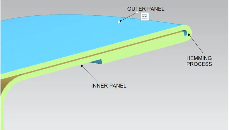
Fig. 16: Hemming of inner and outer panel of back door.
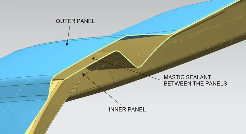
Fig. 17: Mastics to be used between inner and outer panels.
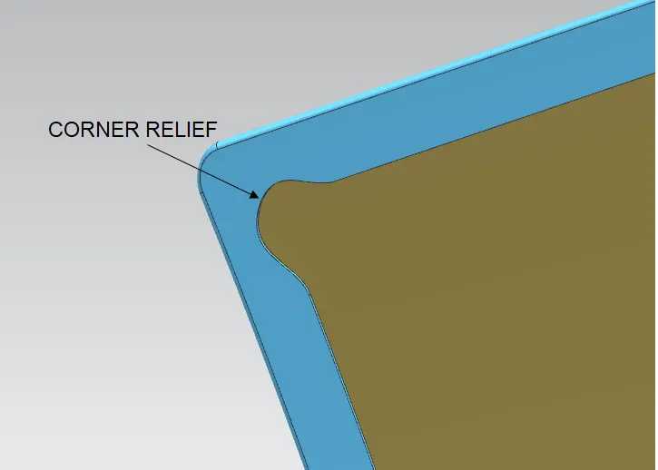
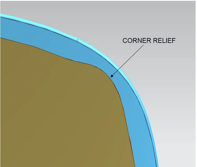
Fig. 18: Corner relief provided for hemming process.
The back door assembly is shown below:
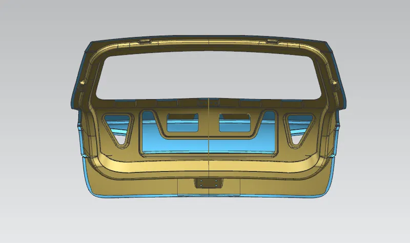
Fig. 19: Front View of Back Door Assembly.
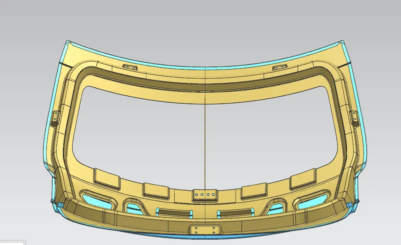
Fig. 20: Top View of Back Door Assembly.
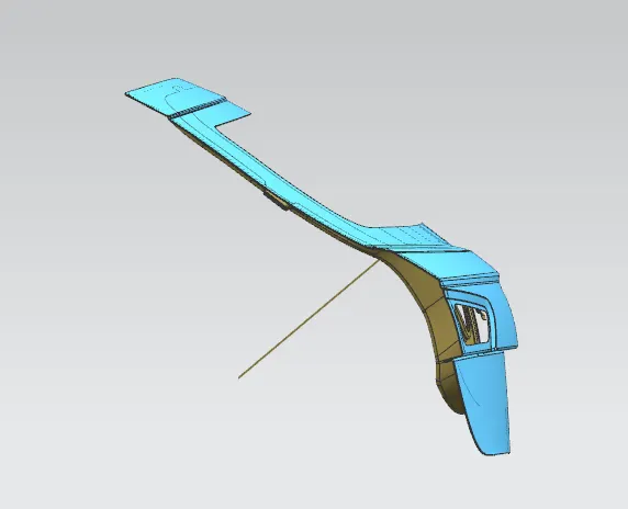
Fig. 21: Right Side View of Back Door Assembly.
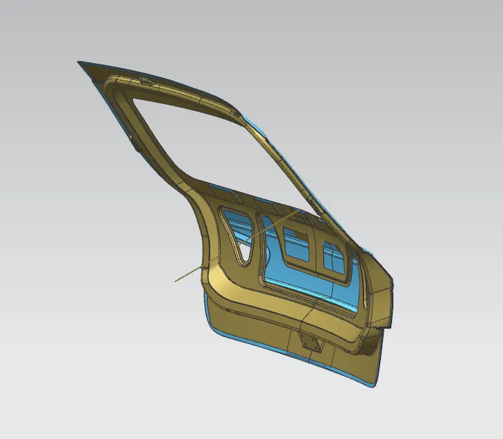
Fig. 22: Isometric View of Back Door Assembly.
Conclusion: The design of back door assembly was completed successfully.