Creating Conceptual mass in REVIT and Creation of Sinusoidal curve and a Parametric stadium using Dynamo
1.ans.:) Aim:- Using Dynamo creating a set of sinusoidal points and creating a curve and creating a surface out of the curve.
Tools used:- Revit software, Manage tab, Dynamo, Code blocks, Point by coordinates block, Sliders, Sin curves, Nerbscurves by control points etc.
Dynamo is an open source visual programming language for Revit, written by designers and construction professionals. It is a programming language that allows you to type lines of code; while also creating an algorithm that consists of nodes.
Using Dynamo, we can work with enhanced BIM capabilities in Revit. Dynamo and Revit together can be utilized to model and analyze complex geometries, automate repetitive processes, minimize human error, and export data to Excel files and other file-types not typically supported by Revit. Dynamo can make the design process more efficient, with an intuitive interface and many pre-made scripting libraries available as well.
For creating a set of sinusoidal points, creating a curve and creating a surface out of the curve in Dynamo:-
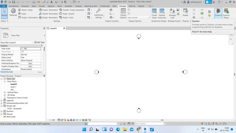
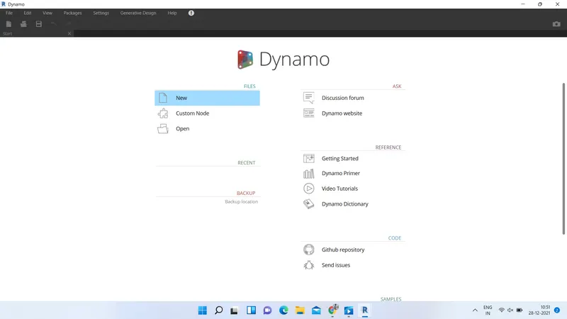
- Open the Revit software and go to Manage tab. Go to Dynamo and open New Dynamo window.
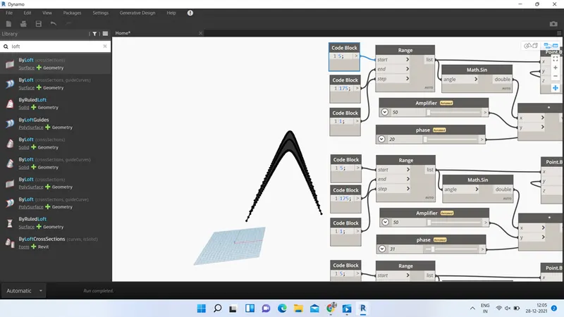
- Search and Enter Codeblocks,Range,Point by coordinates. Assign start,end,step values and Join it to points by coordinates. Sinusoidal points will be created.
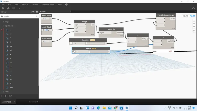
- Now we have to create a curve using these points. For that, enter sin function, sliders for amplifier and phase and Nurbscurve block. Enter product function to increase phase angle.Enter values and connect blocks. A Curve will be created.
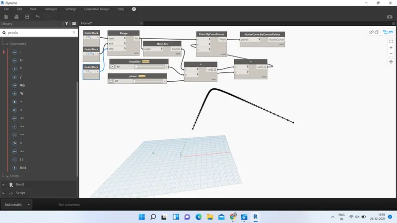
As we have to create surface now we will copy entire group as created first and paste it two times.Adjust the curves by sliding phase value. We can see three curves.
- Enter list block and add 3 items to that. Link three curves to list items repectively.
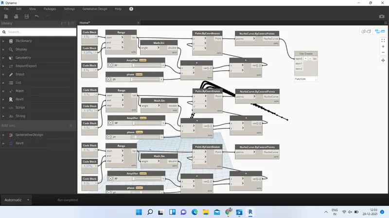
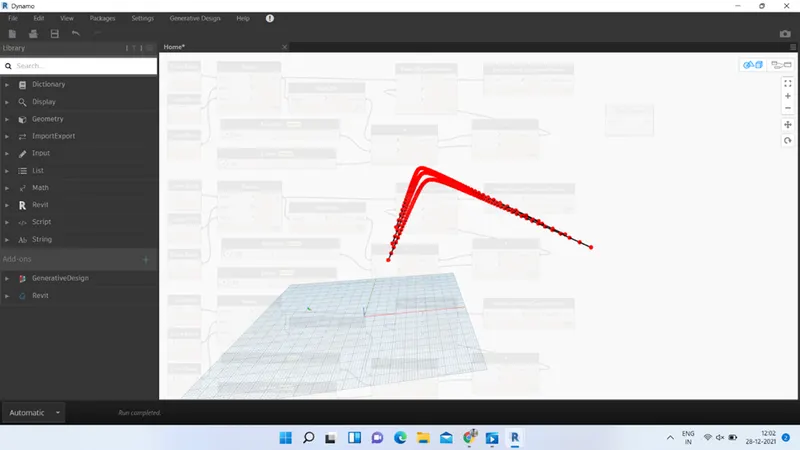
- Now search and enter the Surface by loft and link list block to surface block. Our surface will be created as shown below.
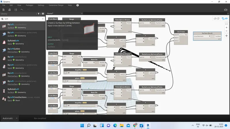
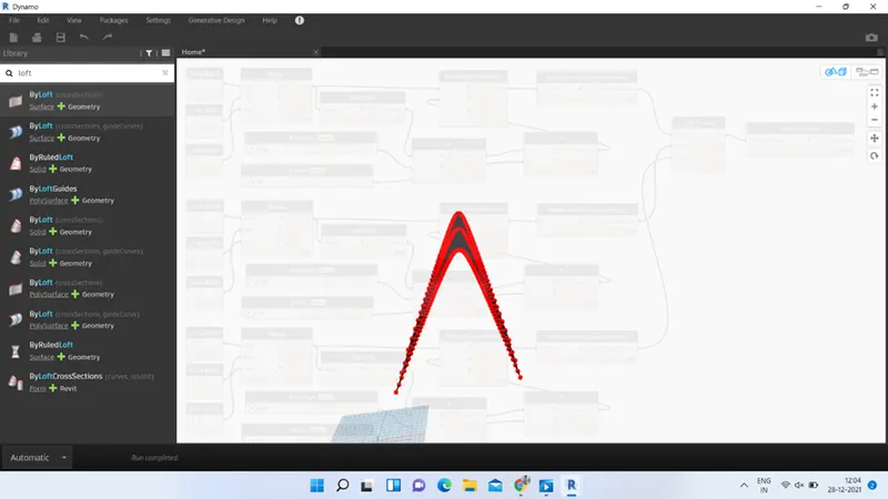
Results:-
Our sinusodial curve and surface are created as desired.
2.ans.) Aim:- Creating a conceptual layout of floor plan in dynamo and Using the tools available in dynamo linking the lines to appropriate model elements in Revit by choosing the wall types and wall parameters.
Tools used:- Revit software, Manage tab, Dynamo, Code blocks, Point by coordinates block, Sliders, Wall types, wall by curve and height, floors etc.
Dynamo is an open source visual programming language for Revit, written by designers and construction professionals. It is a programming language that allows you to type lines of code; while also creating an algorithm that consists of nodes.
Using Dynamo, we can work with enhanced BIM capabilities in Revit. Dynamo and Revit together can be utilized to model and analyze complex geometries, automate repetitive processes, minimize human error, and export data to Excel files and other file-types not typically supported by Revit. Dynamo can make the design process more efficient, with an intuitive interface and many pre-made scripting libraries available as well.
For Creating a conceptual layout of floor plan in dynamo:-
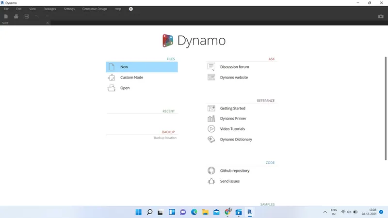
- Open revit and open dynamo from manage tab.
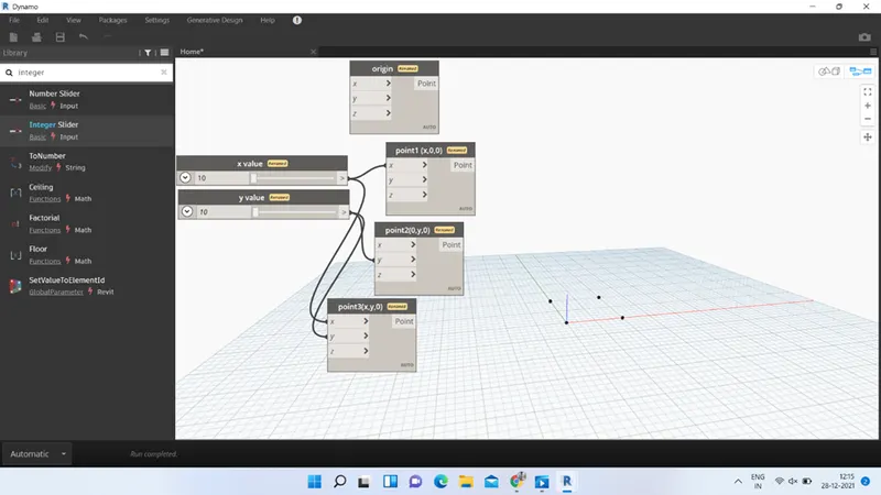
- Enter sliders for X and Y values and enter pointbycoordinates blocks for Cartesian ordinates. Enter values and link them. Coordinate points will be fixed.
- Now enter Linebystartpointendpoint block and draw lines by linking coordinate points.
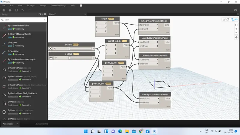
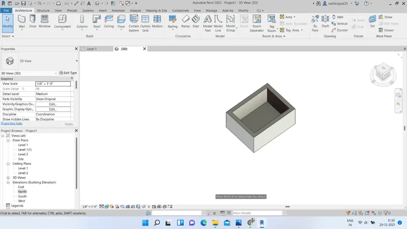
- Thus plan for outer wall boundary will be created. Create a list using lines created. Now search and enter wallbycurveand height block. Enter wall types and levels block. Enter a slider and rename that as height.
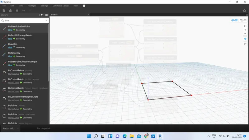
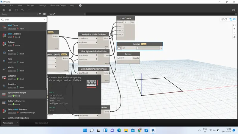
- Select the level and wall types and Connect all parameters to wall block. Wall will be created.
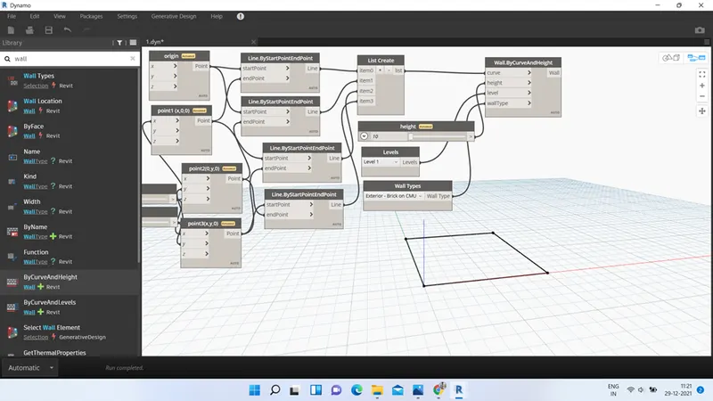
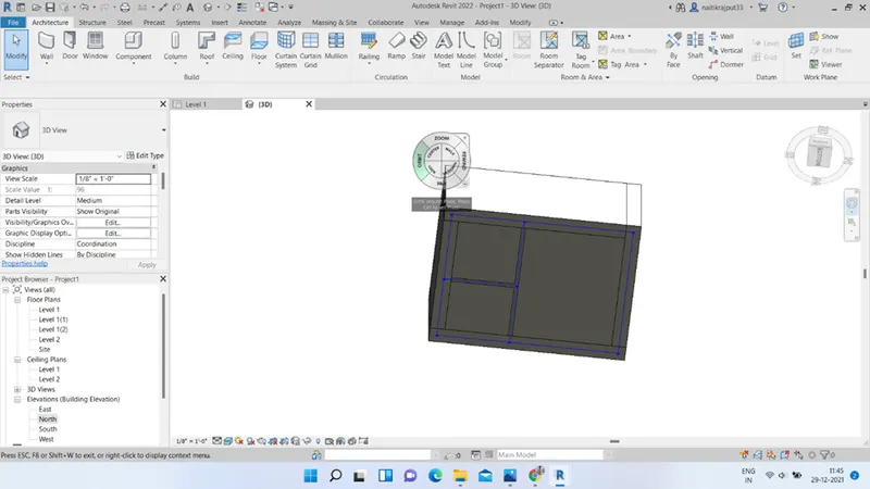
- Go to Revit 3D view to visualise wall created. Using Sliders we can vary length and breadth of walls.
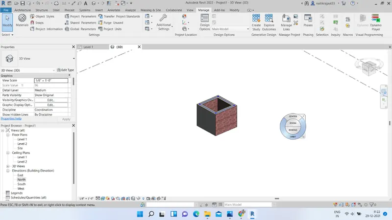
- Vary the length and breadth using sliders and Add floor using floor types.
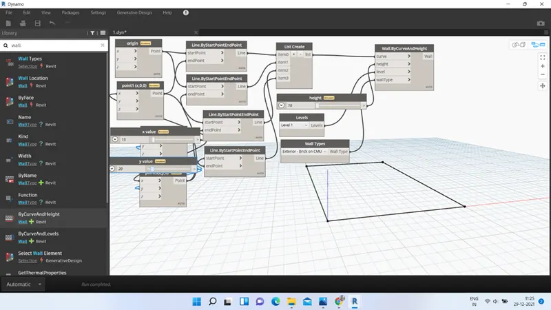
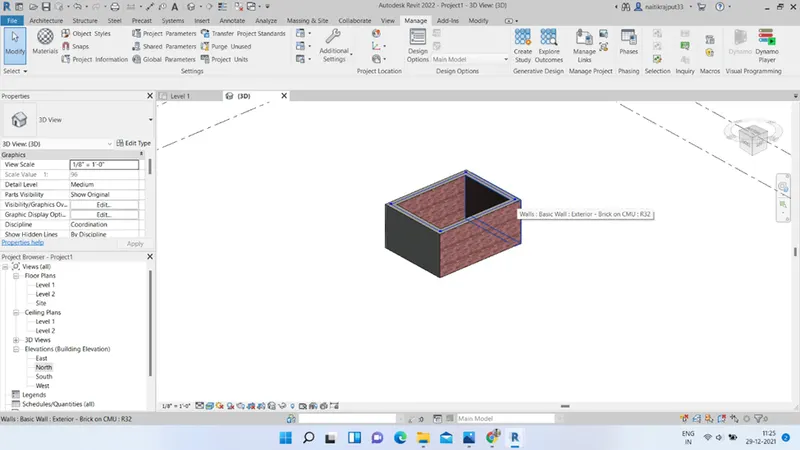
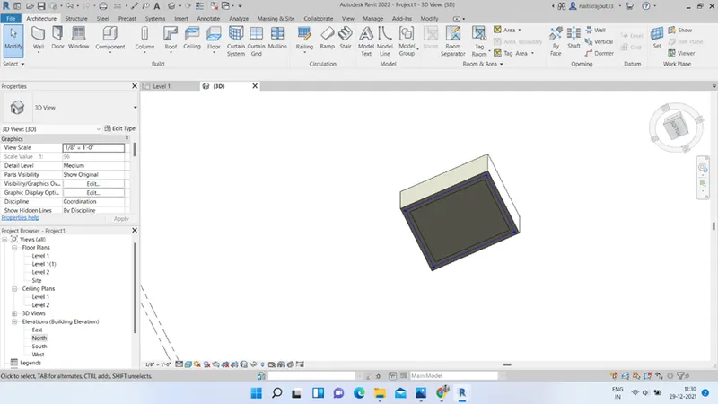
- Go to Dynamo and repeating above steps create inner partition walls using codeblocks, coordinates blocks, sliders and wall types.
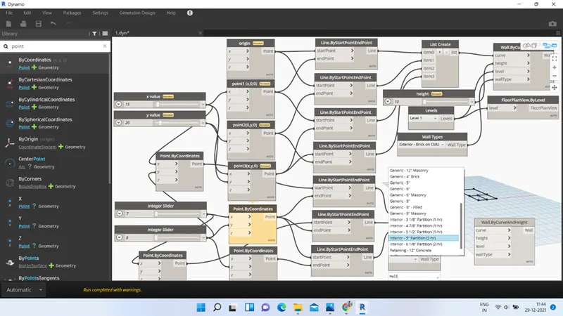
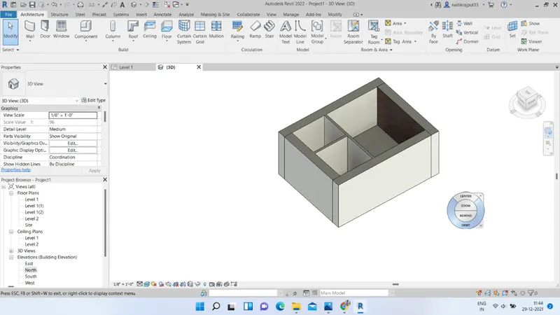
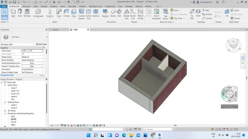
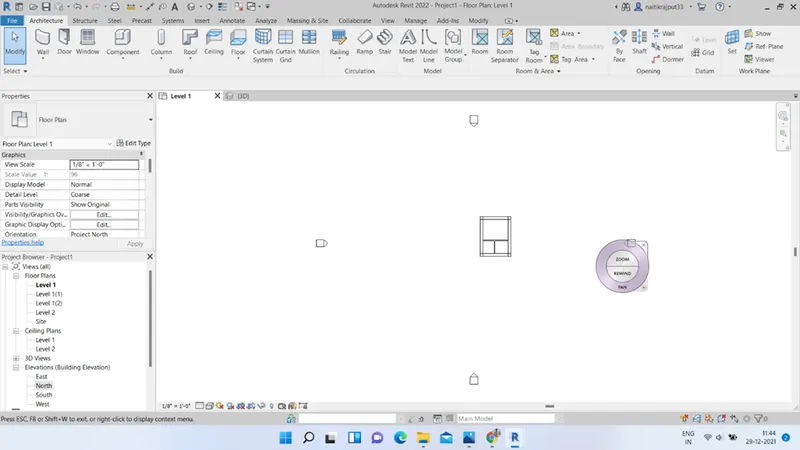
Results:-
Our desired conceptual floor plan is created and can be visualised in Revit 3D view.
3.ans.) Aim:- Creating an array of model elements in Revit. Using dynamo varying the properties of model elements by using the slider or code block.
Tools used:- Revit software, Architecture tab, Column, Manage tab, Dynamo, Code blocks, Sliders, Selectmodelelements block, rotation block etc.
Using Dynamo, we can work with enhanced BIM capabilities in Revit. Dynamo and Revit together can be utilized to model and analyze complex geometries, automate repetitive processes, minimize human error, and export data to Excel files and other file-types not typically supported by Revit. Dynamo can make the design process more efficient, with an intuitive interface and many pre-made scripting libraries available as well.
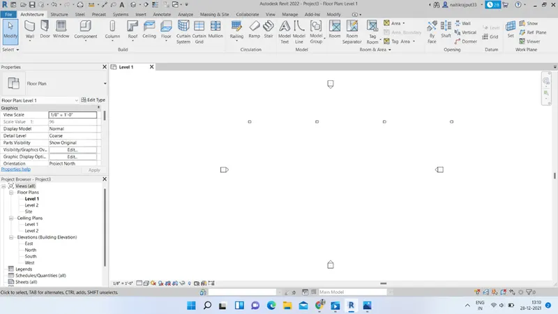
- Open Revit and go to architecture tab. Using columns create an array of columns.

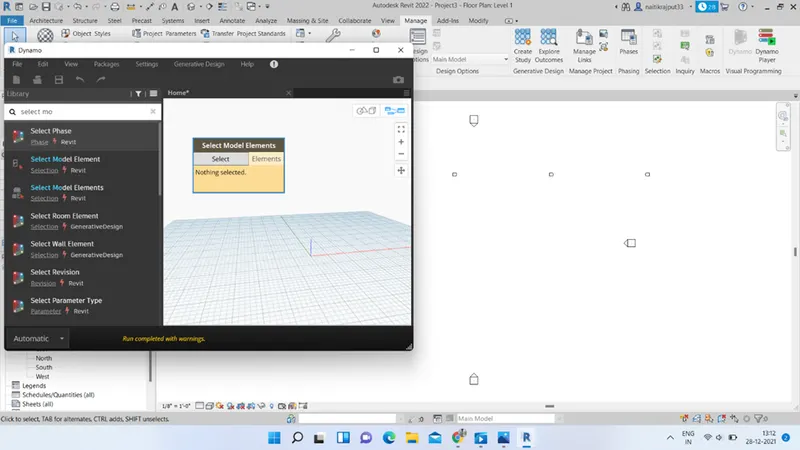
- Now, goto manage tab and open Dynamo. Enter selectmodelinstance block and a slider for rotation degree. Now enter set rotation block for rotation.
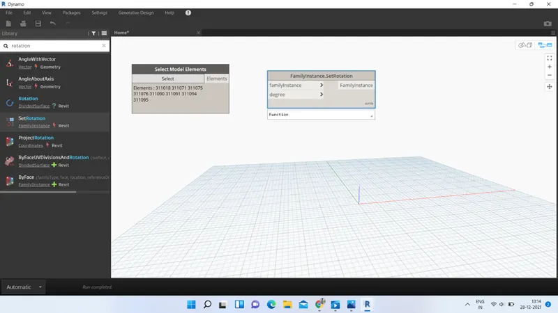
- Click on Select option in selectmodelinstance block and Select all columns from revit window. Provide a set of values for rotation in slider and link both blocks to set rotation block.
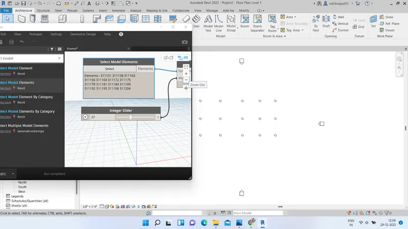
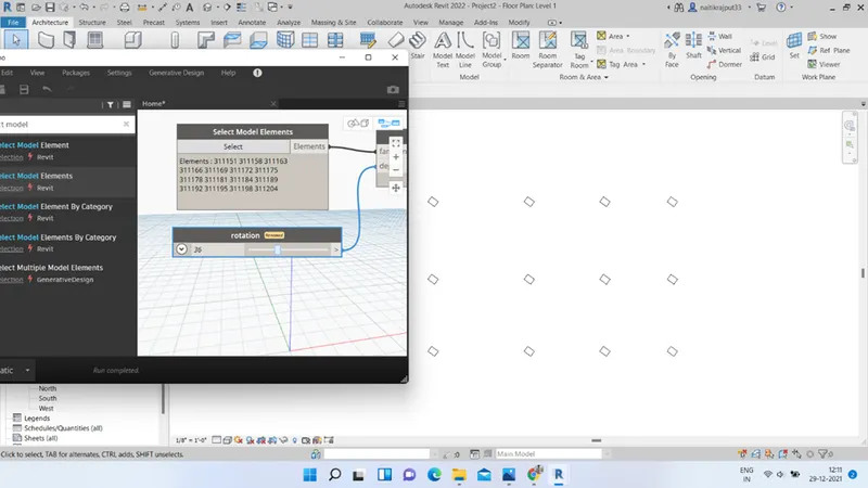
- As we will slide through various values our selected model element will be rotated through in Revit window.
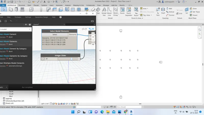
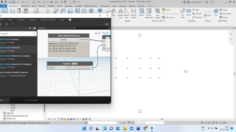
Results:-
Properties of model element is varied using sliders of Dynamo.
4.ans.:) Aim:- Creating a conceptual mass in Revit and developing a parametric column by dividing the surfaces.
Tools used:- Revit, Family model, Modify tab, Set planes etc.
Creating conceptual mass families means that the mass is external to the project. It uses the same tools to create the mass family, which is then saved and loaded into the project.
- Open Revit and select New under Family option. Select Conceptual Mass template and then Metric mass and click OK.
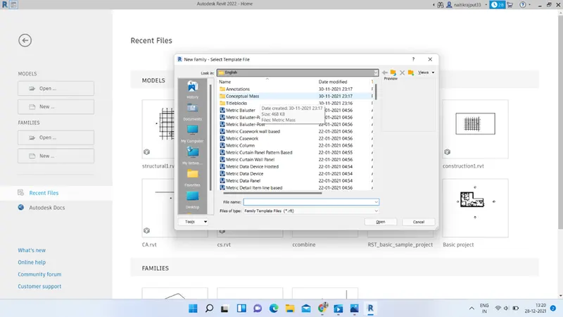
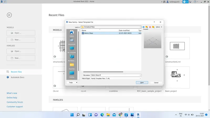
- Create different levels at desired height and Draw a reference polygon at all levels using Draw toolbar.
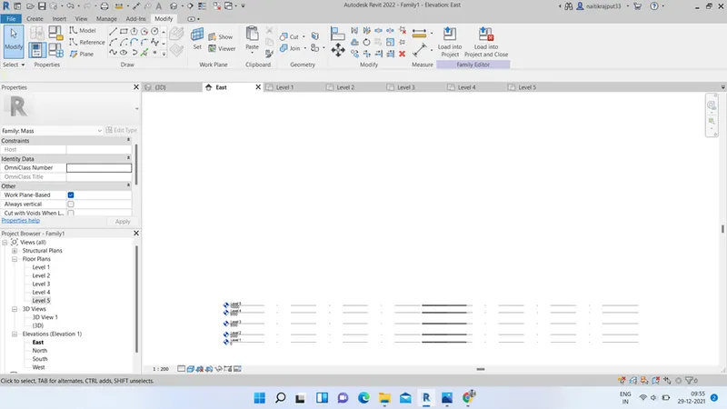
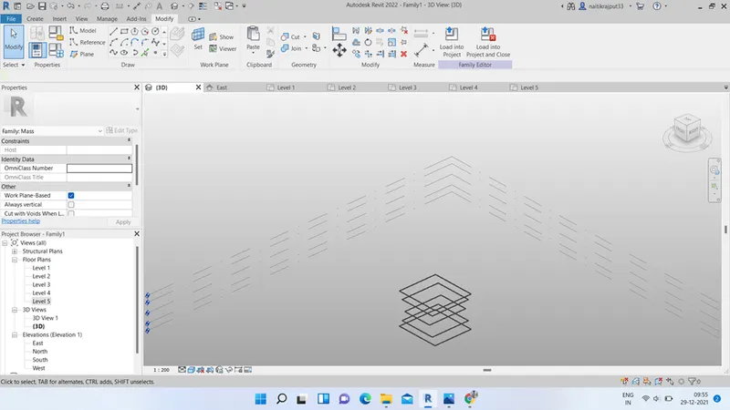
- Now select a Polygon at desired level and Set plane. Now using Draw toolbar draw a polygon of desired sides horizontal to reference polygon in that level.
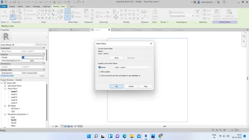
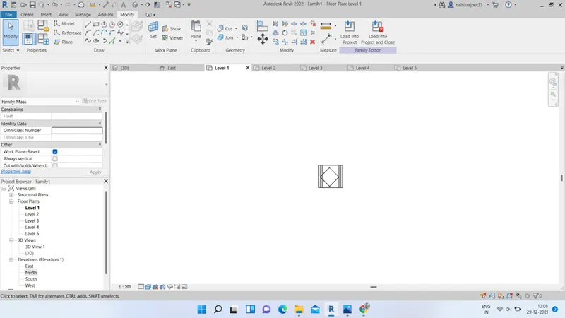
- Repeat the step to draw horizontal poygons in all levels by setting plane.
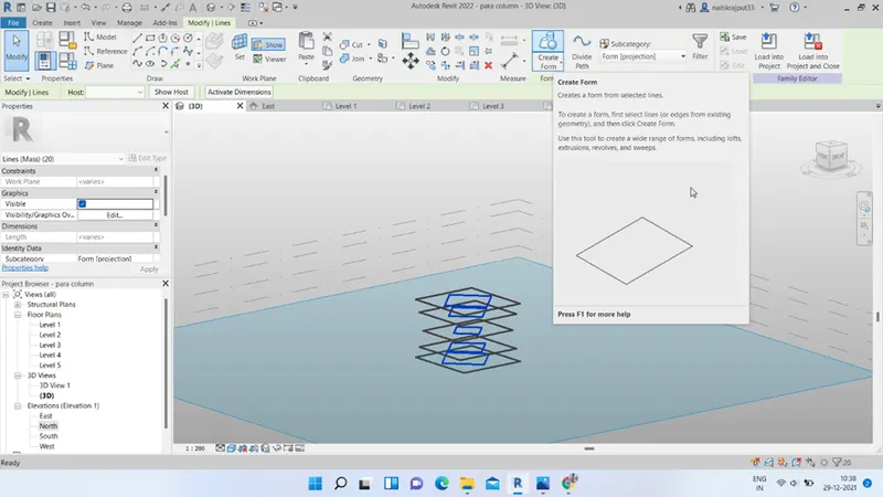
- Now select all drawn polygons and click on Create Form option from modify tab.
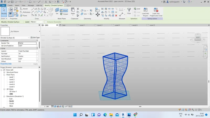
- A form for column will be created.
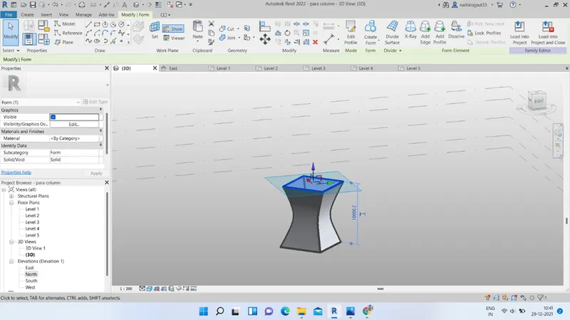
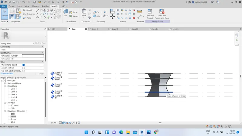
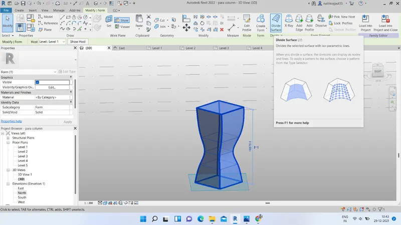
- Now select the form and Click on divide surface. We can see in properties browser that there is no pattern added. Add triangular bent pattern via property browser and click Apply.
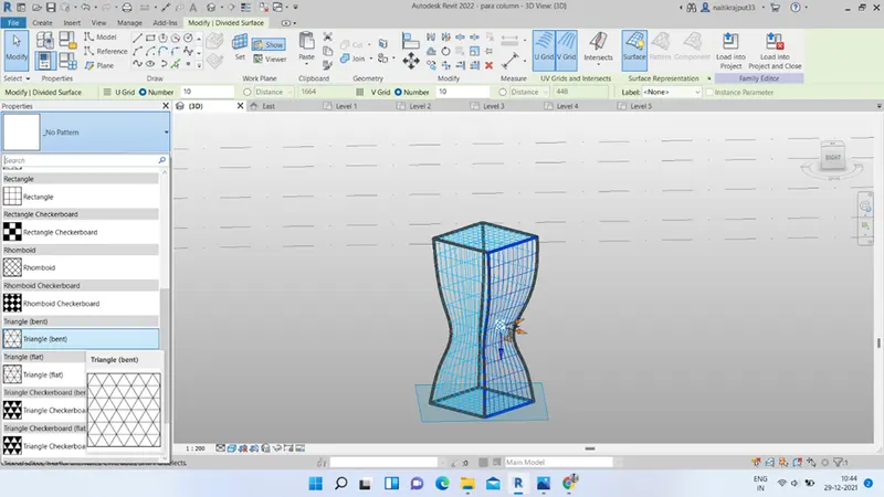
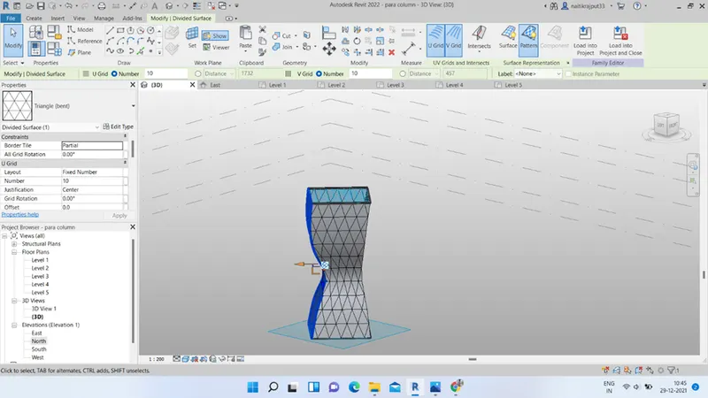
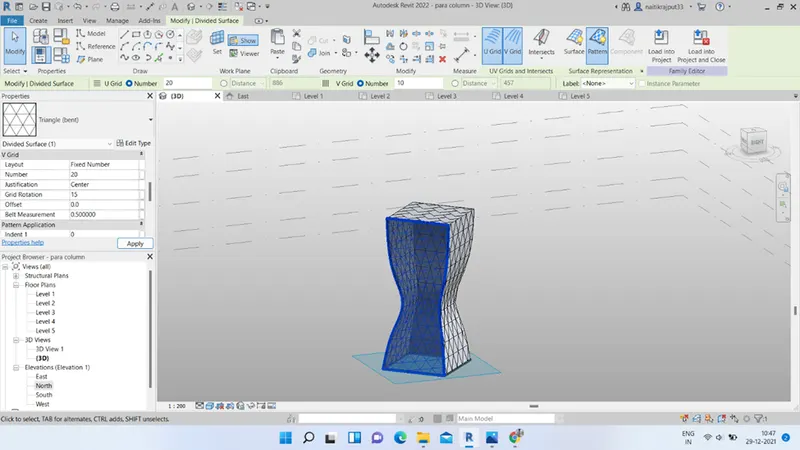
- Our Parametric Column is ready. We can adjust U, V grids parameters for better finish. Select a face and alter the parameters as desired.
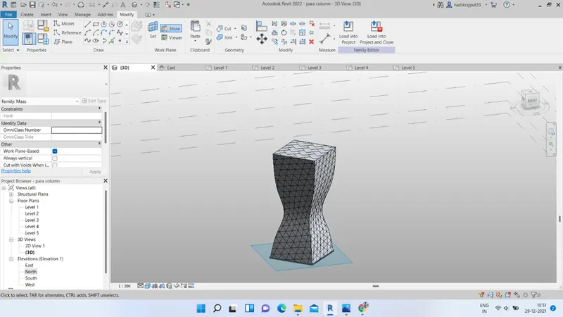
Results:-
A Parametric Column is modelled as seen below:-

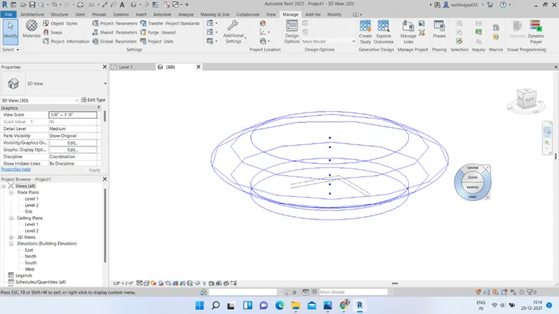
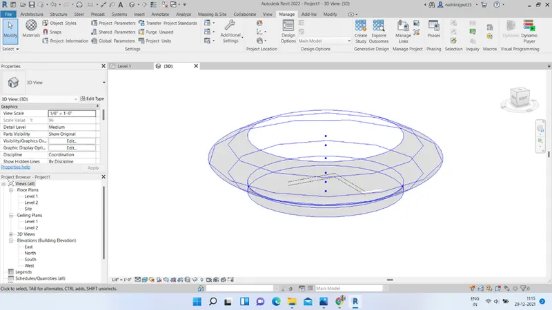
5.ans.:) Aim:- Developing a Parametric Stadium using Dynamo.
Tools used:- Revit software, Manage tab, Dynamo, Code blocks, Point by coordinates block, Integer Sliders, circlebycentreandradius block, Listcreate lock, Surfacebyloft block etc.
Dynamo is an open source visual programming language for Revit, written by designers and construction professionals. It is a programming language that allows you to type lines of code; while also creating an algorithm that consists of nodes.
Using Dynamo, we can work with enhanced BIM capabilities in Revit. Dynamo and Revit together can be utilized to model and analyze complex geometries, automate repetitive processes, minimize human error, and export data to Excel files and other file-types not typically supported by Revit. Dynamo can make the design process more efficient, with an intuitive interface and many pre-made scripting libraries available as well.
For creating a Parametric stadium in Dynamo:-
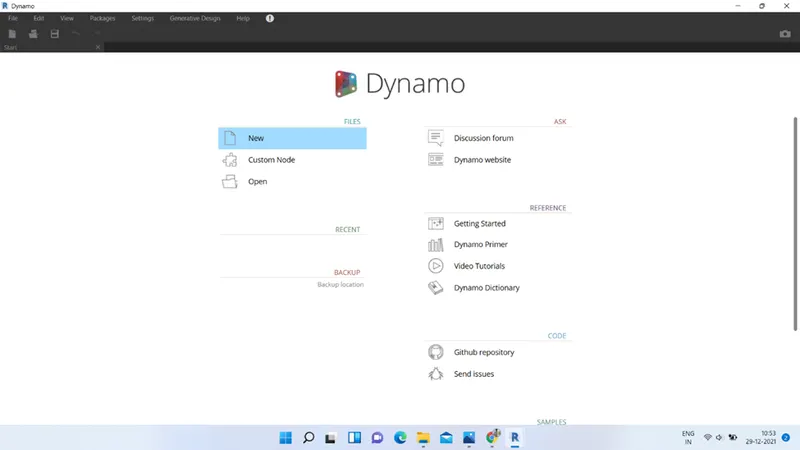
- Open the Revit software and go to Manage tab. Go to Dynamo and open New Dynamo window.
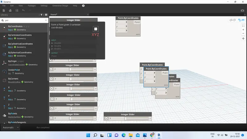
- Search and Enter Integer Sliders, Point by coordinates. Assign name as height and radius to sliders and Join height to points by coordinates. Coordinate point will be created.
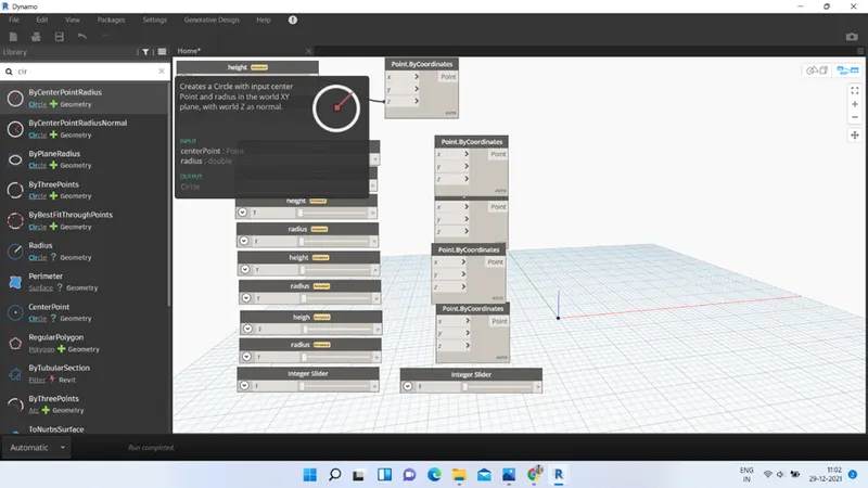
- Now we have to create a circle using this point. Enter circlebycentreandradius block. Join coordinate to centre and radius to radius. A Circle will be created.
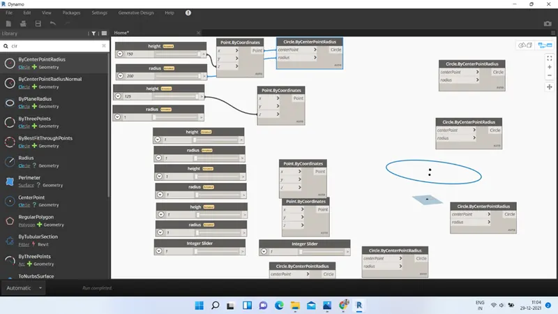
- Similarly create a number of circles with varying height and radiuses.
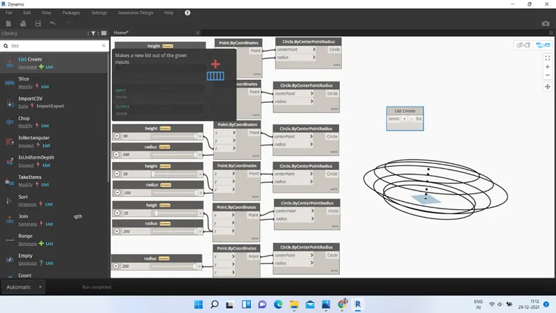
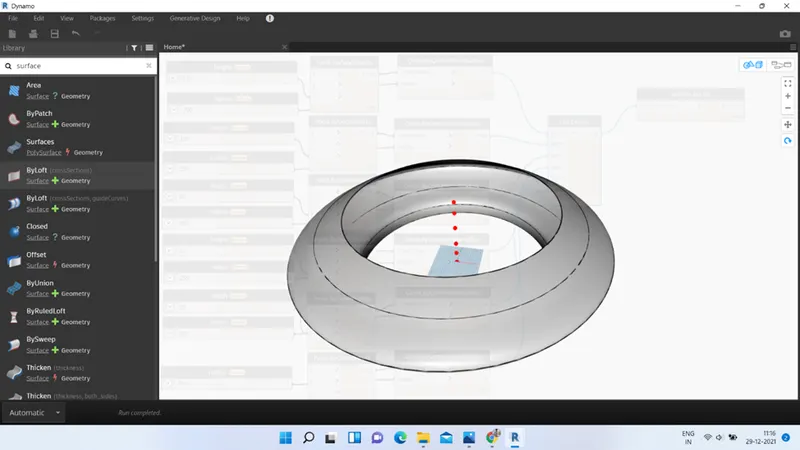
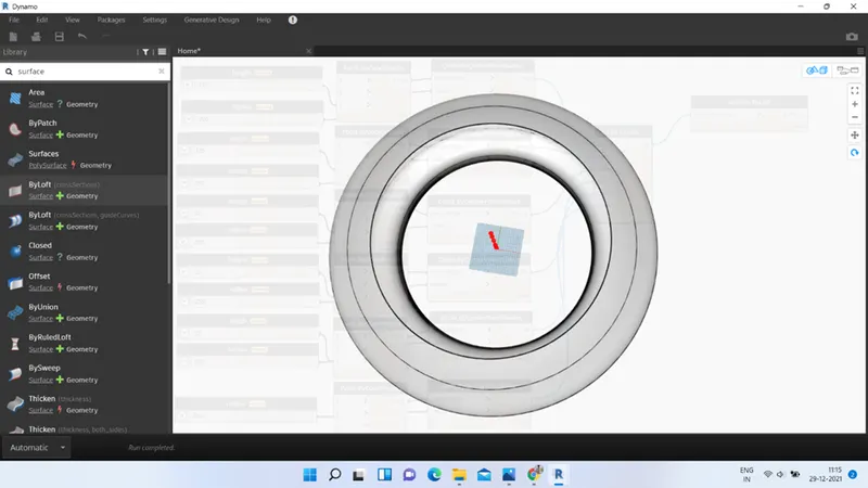
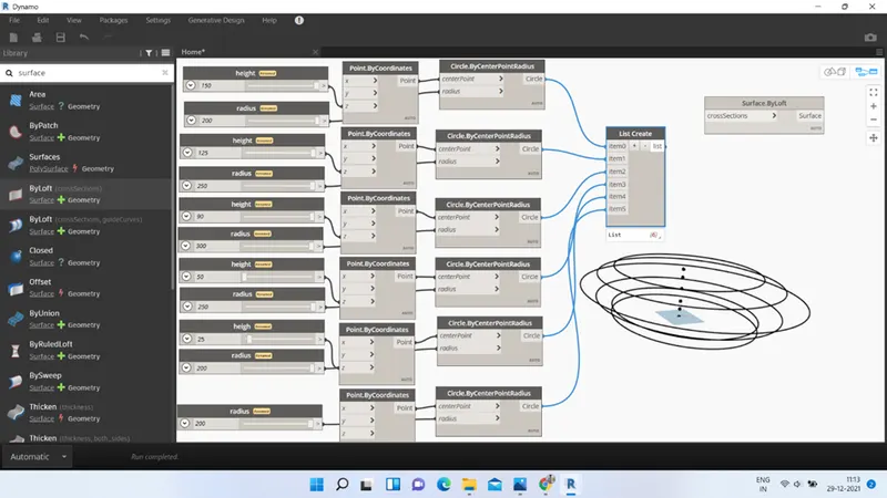
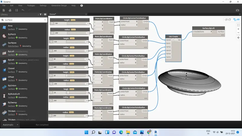
- Enter listcreate block and add all circle items to that. Search and enter surface by loft block. Join listcreate to surface block. Our desired parametric stadium is created.
Results:-
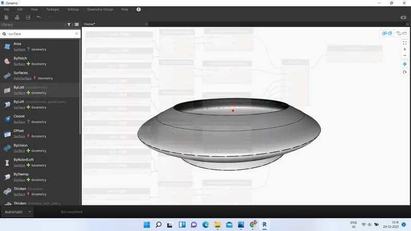
Our desired parametric stadium is created and can be visualised by Revit 3D view too.