Creating a Floor plan, Footing detail and Isometric view using AutoCad
AIM:
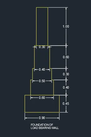
Create a cross section of load bearing wall foundation in AutoCAD
INTRODUCTION:
The geometry of cross section load bearing wall foundation is created by using polyline and line command. The coordinate is used direct distance method. The dimension of each geometry shown in figure.
PROCEDURE:
In AutoCAD create new drawing a dialog box open for unit and template setting, select metric through start from scratch and select acadiso.dwt through template.
Open unit setting by giving command UN select precision 0.00 and select meters.
Grid mode off (F7), Ortho mode on (F8) and snap mode on (F3) we can also do with status bar
Type PL for polyline, click left button of the mouse and move cursor right enter 0.9(because the direction of line anti-clock wise)
Move cursor up side enter 0.45
Move cursor left side enter 0.15
Move cursor up side enter 0.40
Move cursor left side enter 0.05
Move cursor up side enter 0.30
Move cursor left side enter 0.05
Move cursor up side enter 0.60
Move cursor left side enter 0.05
Move cursor up side enter 1
Move cursor left side enter 0.3
Move cursor down side enter 1
Move cursor left side enter 0.05
Move cursor down side enter 0.6
Move cursor left side enter 0.05
Move cursor down side enter 0.3
Move cursor left side enter 0.05
Move cursor down side enter 0.4
Move cursor left side enter 0.15
Move cursor down side enter 0.45 or C enter and press Esc
L enter pick 4th point from start and move cursor left to create horizontal line.
L enter pick 10th point from start and move cursor left to create horizontal line.
go to annotation tool select linear command and represent the dimension of the drawing.
RESULT:
Result obtained from given data is shown in picture
AIM:
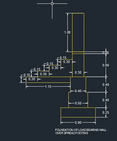
Create a cross section of load bearing wall for spread foundation in AutoCAD
INTRODUCTION:
The geometry of cross section load bearing wall foundation is created by using polyline and line command with direct distance method. The dimension of each geometry shown in figure. The drawing is in previous model.
PROCEDURE:
Type PL for polyline, left click and move cursor right enter 0.9(because the direction of line anti-clock wise)
Move cursor up side enter 0.25
Move cursor left side enter 0.2
Move cursor up side enter 0.40
Move cursor left side enter 0.05
Move cursor up side enter 0.40
Move cursor left side enter 0.05
Move cursor up side enter 0.60
Move cursor up side enter 0.05
Again, move cursor up side enter 1
Move cursor left side enter 0.3
Move cursor down side enter 1.65
Move cursor left side enter 0.05
Move cursor down side enter 0.4
Move cursor left side enter 0.05
Move cursor down side enter 0.4
Move cursor left side enter 0.2
Move cursor down side enter 0.25 or C enter and press Esc
L enter pick top left side of 3rd step of the rectangle from bottom
Move cursor left side 0.85 enter
move cursor up side enter 0.15
move cursor right side enter 0.3
move cursor upside enter 0.15
move cursor right side enter 0.3
move cursor up side enter0.15
move cursor right side enter 0.3 and press Esc
L enter pick 1st point of the stairs move left cursor enter 0.3
Move cursor down side enter 0.15
Move cursor left side enter 1.15
L enter create horizontal line between
Track first vertical line of 0.05 move cursor left to create horizontal line
And press Esc to end the line
L enter track 2nd vertical line of 0.05 move cursor left to create horizontal line
go to annotation tool and represent the dimension of the drawing.
RESULT:
Result obtained from given data is shown in picture
AIM:
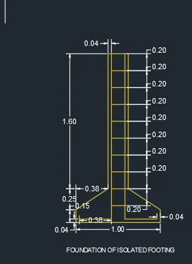
Create a cross section of isolated footing in AutoCAD
INTRODUCTION:
The cross section of the isolated footing is to created by the help of draw tool, modify tool and annotate tool. The coordinate is used direct distance method. The dimension of each geometry shown in figure. The drawing is in previous model.
PROCEDURE:
Type PL for polyline, left click and move cursor right enter 1 (because the direction of line anti-clock wise)
Move cursor up side enter 0.15
Move cursor up side enter @ -0.38, 0.25
Move cursor up side enter 1.6
Move cursor left side enter 0.24
Move cursor down side enter 1.6
Move cursor down side enter @ -0.38, -0.25
Move cursor down side enter 0.15 or C enter
O enter for offset specify offset distance 0.04 enter
Pick line anywhere move cursor inside of the drawing and left click
Press Esc, Now trims the unnecessary line inside of the drawing
TR enter left click anywhere of inside line, enter
Left click for both incline line and top horizontal internal line enter
Now extend the internal vertical lines to top and bottom
EX double enter for extend lines
Left click one by one vertical line, top and bottom
TR double enter move cursor bottom between vertical lines select (left click) horizontal line to trim
Press Esc, L of the bar is extra, so we move the cursor upon the line left click
Pick top grip of line and drag down to mid of the line then left click apply both side press Esc
Now provide stirrup, L enter move cursor top corner of the footing
Left click create horizontal line till left or right side of the vertical bar left click enter
Then trim the extra line TR double enter left click on the extra bar press Esc
CO enter select horizontal line enter
Specify base point left click (right or left side of the line)
A enter specify the number of items 8 enter
Keep cursor upside and specify fit 0.2 enter press Esc
One balance stirrup offset downside
O enter Specify offset distance 0.2 enter
Select first line of the stirrup and move cursor down side left click press Esc
go to annotation tool and represent the dimension of the drawing.
RESULT:
Follow this procedure to obtained the drawing of cross section of the isolated footing.
AIM:
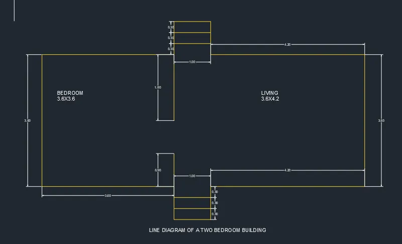
Create a line diagram of two bedroom building in AutoCAD
INTRODUCTION:
The diagram is created by the help of tools like draw tool, modify tool and annotation tool. Direct distance method coordinate is used to draw the diagram. Last drawing model are used to draw the diagram. Each and every dimension shown in the drawing.
PROCEDURE:
L enter, left click and move cursor right enter 3.6 (direction of line is anti-clock wise)
Cursor move down 0.3 enter
Cursor move down 0.6 enter
Cursor move right 1 enter
Cursor move up 0.9 enter
Cursor move right 4.2 enter
Cursor move up 3.6 enter
Cursor move left 4.2 enter
Cursor move up 0.9 enter
Cursor move left 1 enter
Cursor move down 0.9
Cursor move left 3.6 enter
Cursor move down 3.6 enter or C enter
L enter, track the end point of 0.3 left click
Move cursor right attach to vertical line, left click and Esc
O enter specify offset distance 0.3 enter
Left click the object move cursor down side and left click, enter
Now opposite side same stairs make with mirror command
MI enter select both line (left click move cursor right to left-down both line in region then left click) enter
Move cursor 1st vertical line of 3.6, left click at mid-point of the line and move cursor opposite vertical line mid-point, left click
Erase source object no enter
L enter track 1st horizontal line of 3.6, pick end point of the line (left click)
Move cursor upside 0.9 enter Esc
L enter pick opposite side of the 1st horizontal line (left click)
Move cursor down side 1.8 enter Esc
go to annotation tool and represent the dimension and text of the drawing.
RESULT:
Followed step by step procedure to obtain the result
AIM:
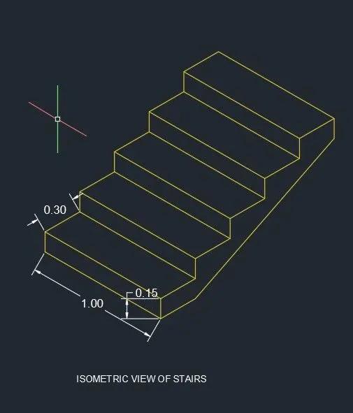
Create an isometric view of stair case (steps) in AutoCAD
INTRODUCTION:
The view of stair case looks like 3D due to isometric drafting, but not 3D drawing. The drawing is 2D made by the help of isometric drafting, draw tool, annotation tool and modify tool. Direct distance method coordinate is used to draw the diagram. All the drawings made in single model. Each and every dimension shown in the drawing.
PROCEDURE:
Keep on isometric drafting in status bar and select isoplane left by pressing Fn+F5
L enter left click move cursor north west 1 enter
Move cursor north 0.15 enter
Move cursor east south 1 enter
Move cursor south 0.15 enter or C enter
Change isoplane right
L enter pick top north west corner point
Move cursor north east 0.3 enter Esc
L enter pick top east south corner point
Move cursor north east 0.3 enter Esc
Select whole object (left click move cursor right to left-down or up all object in green region then left click)
CO enter pick bottom south point
A enter specify number of items 5 enter
Pick top north east point Esc
Change isoplane left
L enter track top north west point of the diagram left click
Move cursor east south 1 enter
Move cursor south 0.15 enter Esc
Change isoplane right
L enter track bottom south point of the diagram left click
Move cursor north south 0.3 enter
Move cursor north bottom point to connect the line Esc
go to annotation tool and represent the dimension and text of the drawing.
RESULT:
The final result obtained by followed procedure
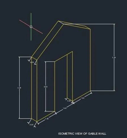
AIM:
Create an isometric view of Gable wall in AutoCAD
INTRODUCTION:
The view of wall looks like 3D due to isometric drafting, but not 3D drawing. The drawing is 2D made by the help of isometric drafting, draw tool, annotation tool and modify tool. Direct distance method coordinate is used to draw the diagram. All the drawings made in single model. Each and every dimension shown in the drawing.
PROCEDURE:
Keep on isometric drafting in status bar and select isoplane left by pressing Fn+F5
L enter left click move cursor north west 0.3 enter
Move cursor north 3 enter
Move cursor east south 0.3 enter
Move cursor south 3 enter
Change isoplane top
Move cursor north east 1 enter
Change isoplane left
Move cursor north 2.42 enter
Move cursor north east 1 enter
Move cursor south 2.42 enter
Move cursor north east 1 enter
Move cursor north 3 enter Esc
Change isoplane right
L enter create temporary line at bottom side between the opening Esc
L enter track midpoint of the temporary line left click
Move cursor north 4 enter
Line continues connect with south-west, north-east and end Line at start point Esc
Select temporary lines and delete
Change isoplane left
L enter pick top north point
Move cursor north west 0.3 enter
Connect south west point Esc
L enter pick north east point 0.3 enter
Move cursor left to connect top north point
go to annotation tool and represent the dimension and text of the drawing.
RESULT:
The final result obtained by followed procedure