Centrifugal pump simulation project
Introduction:
- The hydraulic machine which converts mechanical energy into hydraulic energy is called a pump. The hydraulic energy is basically in the form of pressure energy.
- If the mechanical energy is converted into pressure energy, by means of centrifugal force acting on the fluid, the hydraulic machine is called a centrifugal pump.
- The mechanical energy in the centrifugal pump is basically the rotational kinetic energy which typically comes from an engine or electric motor.
Working of a centrifugal pump:
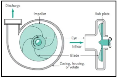
Figure 1:Centrifugal pump
The most important part of the centrifugal pump is the impeller. The impeller is the rotating part of the centrifugal pump which is responsible for pumping the fluid. The impeller consists of radial vanes which extend into the impeller body. The impeller is connected to the shaft of an electric motor. When the impeller rotates, centrifugal force pushes the fluid outwards and into the casing of the impeller. This creates a low pressure at the suction port of the impeller. This low pressure is to suck the water into the pump as the water hits the wall of the casing the kinetic energy is converted into potential energy this potential energy is responsible to drive the water out of the casing. The casing of the impeller is designed in the manner of the increasing area along the direction of flow. This type of casing is called a volute & this is the most common design.
Types of impeller:
They are three types of the impeller are there which are as follows:
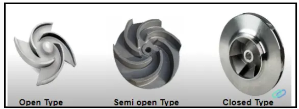
Figure 2:Types of the impeller
- Open type impeller
- Semi-open type impeller
- Closed type impeller
The impeller type is chosen based on the liquid. If the working liquid is cloggy and has a lot of sediments in it, an open type impeller is used. If the working fluid is clean with no impurities in it, a closed type impeller is used. If a closed type impeller is used in murky water, the impurities in the water can clog the impeller and prevent it from functioning properly. Open type impeller is inefficient when compared to closed type impeller.
Advantage:
The centrifugal pump is the most commonly used type of water pump because of the following reasons:
- Ease of manufacturing
- Lightweight
- Easy to maintain & repair
Disadvantage:
Below are the two main dis-advantage of centrifugal pump:
- Priming:
- Priming in centrifugal pumps is required when the elevation of the pump is more than the elevation of the liquid.
- In this case, the impeller is not able to generate sufficient suction pressure to lift the water against gravity from its resting surface this is because a centrifugal pump works by pushing the water through centrifugal force instead of sucking it because of this the impeller needs to be primed this is normally done by filling the casing & the pipes of the pump with the working liquid an external priming port is provided to do this.
- Cavitation:
- Cavitation includes the formation of vapour bubbles of the flowing liquid & collapsing of the vapour bubbles.
- Formation of the vapour bubbles of the flowing liquid take place only whenever the pressure in any region falls below the vapour pressure.
- When the pressure of the flowing liquid is less than the vapour pressure, the liquid starts boiling & vapour bubbles are formed this vapour bubbles are carried along with the flowing liquid to higher pressure zone where these vapours condense & bubbles collapse.
- Due to sudden collapsing of the bubbles at the metallic surface, high pressure is produced & metallic surfaces are subjected to high local stress which basically damages the impeller and drastically reduces its life span of the pump.
NPSH: In order to see or to avoid the cavitation the most important term i.e NPSH is used. The term NPSH( Net Positive Suction Head) is very commonly used in the pump industry. The Net positive suction head is defined as:
NPSH=absolute pressure head at the inlet of the pump-Vapor pressure head+velocity head
In the mathematical equation,
NPSH=`frac{punderset(1)()}{rhog}-frac{punderset(v)()}{rhog}+frac{vunderset(s)()^2}{2g}`
By deriving and substituting the value of absolute pressure head we get,
NPSH=`Hunderset(a)()-hunderset(s)()-hunderset(f)()-Hunderset(v)`.....(1)
where,
`Hunderset(a)()`=Atmospheric pressure head
`Hunderset(v)()`=Vapour pressure head
`hunderset(s)()`=maximum suction height
`hunderset(f)()` =Friction head
The right side of the equation is the total suction head. Hence NPSH is equal to the total suction head. Thus NPSH can be defined as the total pressure head required to make the liquid flow from the suction pipe to the pump impeller.
For any pump installation, a distinction is made between available NPSH & required NPSH. The required NPSH will be provided from the pump manufacturer while available NPSH can be calculated from the equation(1) in order to avoid cavitation the available NPSH should be greater than the required NPSH.
Objective:- To simulate the fluid flow through the Centrifugal pump for the following 3 different outflow mass flow rate:
- 130 kg/s
- 156 kg/s
- 180 kg/s
Geometry:
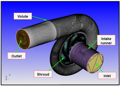
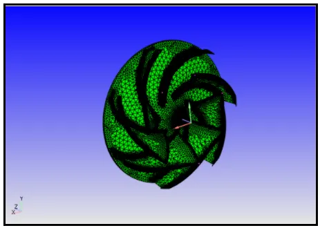
The pre-modelled geometry was imported into Converge and the geometry was inspected for surface error or other errors. After fixing all the errors & the boundaries were flagged & case was set up.
Centrifugal pump
Impeller
Case Setup:
- Application: General Flow
- Solver: Transient solver
- Simulation Type: Liquid
- Material: Air
- Species: H2O
- Simulation mode: Full hydrodynamic
Simulation time parameters:
- Start time:0 sec
- End time:0.2 sec
Region & Initialization:
In this step, we have created a region of the fluid and initialize the species value as: H2O=1
Boundary Conditions:
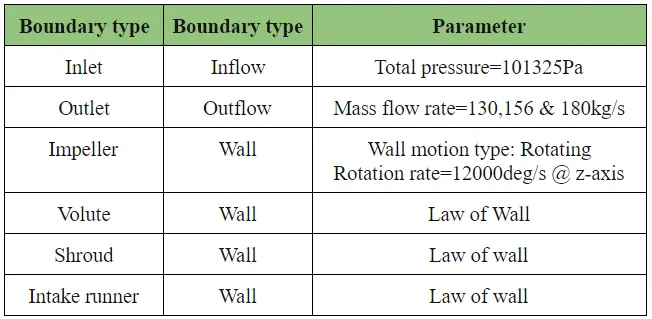
All the boundary conditions are defined at temperature=300K.
Physical Model
Turbulence model:k_e-epsilon
Grid Control:
- Element size:dx = 12e-3m, dy = 12e-3m & dz = 12e-3m
Fixed Embedding
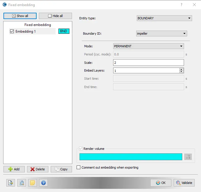
- Fixed embedding is a method which is used to refine the mesh at a particular area.
- In our case, we are more concerned about the area near the Impeller, so for this, we need a more refined mesh for that we used a fixed embedding method.
- Converge uses below formula to refined the mesh:
- Refined mesh=`frac{Base grid}{2^{SCALE)}`
Output Files:
- The time interval for writing 3D output data files: 0.002 sec (So, that we get at least 100 3D output files)
- The time interval for writing text output:1e-6 sec(So, that we get every minute )
- The time interval for writing restarting output:0.001sec
- Maximum number of restart file saved:3
Post-Processing
Mesh:
From the above mesh animation, we can see that the mesh continuously changes around the impeller which is because of the rotation of the impeller
Plots:
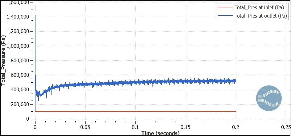
Total pressure plot for 130 kg/s mass flow rate
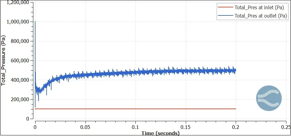
Total pressure plot for 156 kg/s mass flow rate
Total pressure plot for 180 kg/s mass flow rate
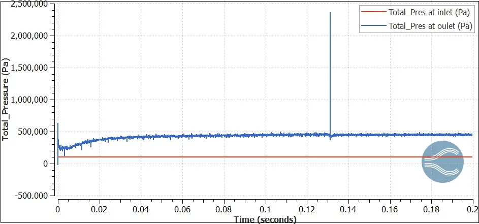
From the above pressure plots, we can see that pressure at the inlet is constant this is because we have provided the pressure boundary condition at the inlet while at the outlet instead of pressure boundary condition we have provided the mass flow rate boundary condition because we need to find out the maximum pressure at the outlet for different mass flow rate & this is what the aim of the centrifugal pump that to increases the pressure at the outlet.
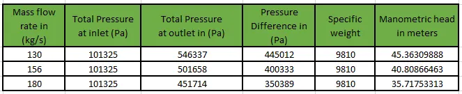
Also, from the above plots, we can calculate manometric Head which is basically the difference in total pressure (in metres) between the pump inlet and outlet.
`Hunderset(m)()=frac{Delta P}{rhog}`
By tabulating the data of the above plot & by using the above formula we can calculate the manometric head which as follows:
Performance plot:
Total Pressure ratio vs Mass flow rate
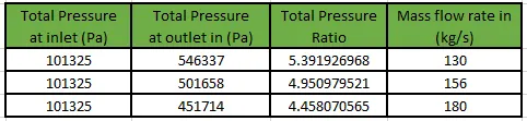
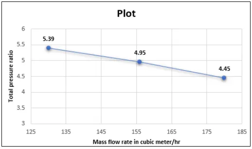
From the above plot, we can see that as the mass flow rate increases the pressure ratio decrease this is because as the mass flow rate increases the friction will increase in the system. This increase in friction will reduce the amount of total pressure that the pump can produce. In fact, as the flow increases, friction increases and the total pressure at the outlet continues to decrease.
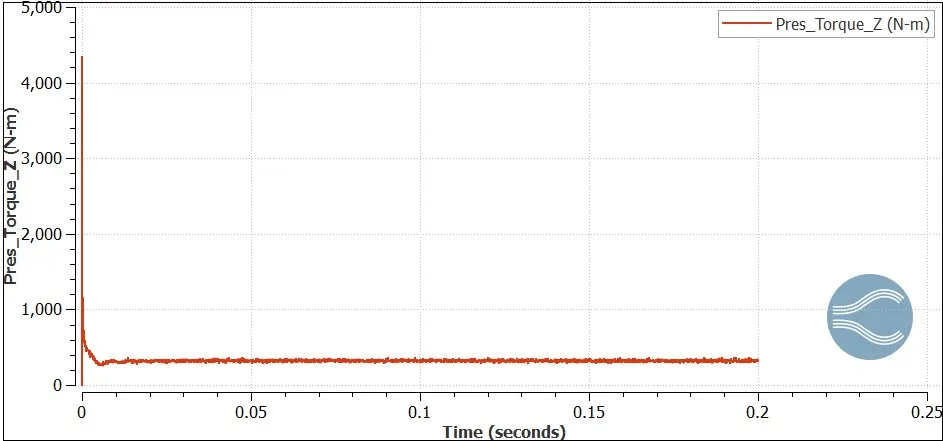
Torque plot for 130 kg/s mass flow rate
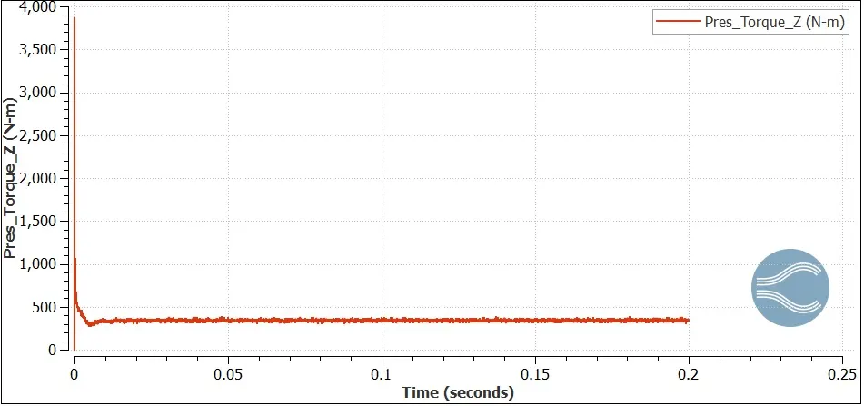
Torque plot for 156 kg/s mass flow rate
Torque plot for 180 kg/s mass flow rate
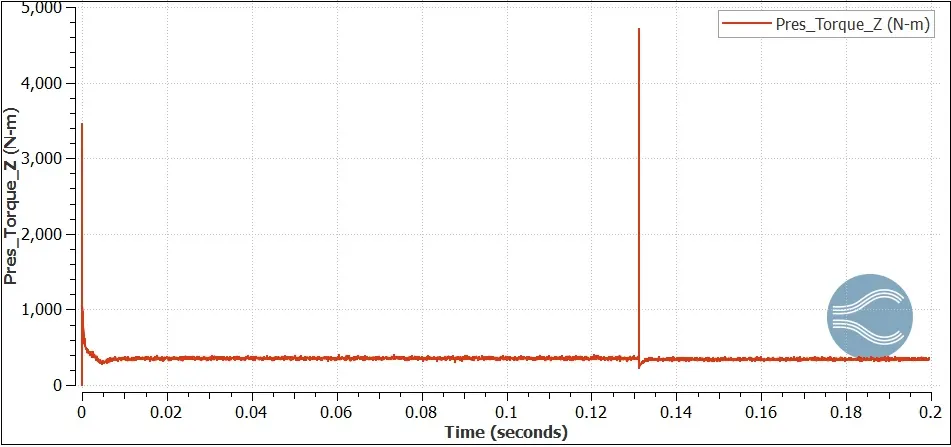
From the above plots, we can calculate Shaft power which is basically the difference in total pressure (in metres) between the pump inlet and outlet.
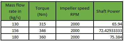
`Punderset(shaft)()=frac{2pixxNxxT}{60}`
By tabulating the data of the above plot & by using the above formula we can calculate the shaft power which as follows:
Characteristic Plot: Mass flow rate v/s Shaft power
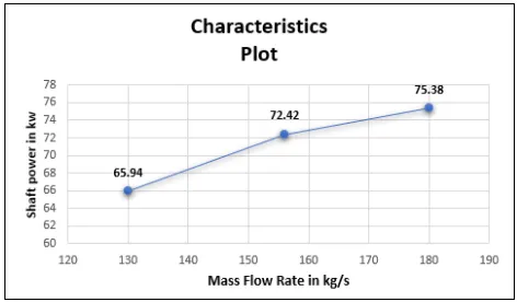
From the above plot, we can see that as the mass flow rate increases the power required to drive the shaft for the same RPM will increase this is because at the maximum flow rate the fluid will push the impeller more which will increase the torque which eventually increases the required shaft power
Pump efficiency: It is defined as the ratio of the power output of the pump to the power input to the pump.
`eta=frac{rhoxxgxxQxxHunderset(m)()}{Punderset(shaft)()xx1000}`
Calculation:

Plot:
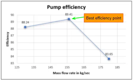
From the above plot, we can see that as mass flow rate increase the efficiency increase up to a point but after that point, the efficiency starts to decrease this is because the increase in mass flow rate will decrease the pressure head which will eventually decrease the efficiency of the pump.
The point up to where the mass flow rate is directly proportional to efficiency is called as Best efficiency point in our simulation we best efficiency point occur when the mass flow rate is 156kg/s as shown above in the above plot
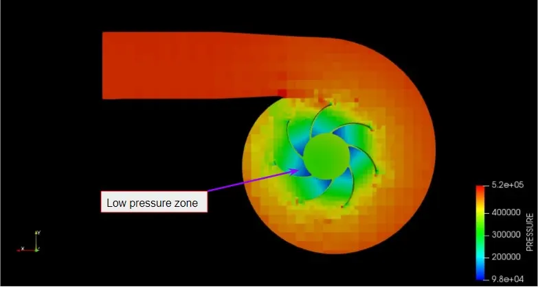
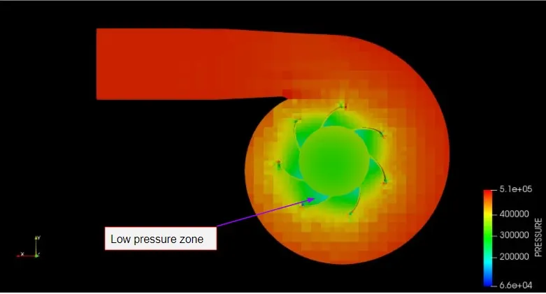
Pressure contour
When mass flow rate=130kg/s
When mass flow rate=156kg/s
When mass flow rate=180kg/s
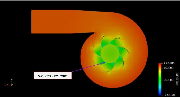
From the above contour, we can see that the low-pressure zone occur at the suction side & when the static pressure in this zone falls below its vapour pressure the cavitation will occur also when we compare above pressure contour amongst each other we see that the low-pressure zone decrease as a mass flow rate increase.
Velocity contour animation:
Conclusion:
Successfully did centrifugal pump simulation for different mas flow rate
The phenomenon like NPSH, Cavitation, Performance plot & BEP is studied.